New Holland TK75VA TK80A TK80MA TK90A TK90MA TK100A Repair Manual 87582124 – PDF DOWNLOAD
Original price was: $65.95.$36.95Current price is: $36.95.
New Holland TK75VA TK80A TK80MA TK90A TK90MA TK100A Repair Manual
Part No : 87582124
Description
New Holland TK75VA TK80A TK80MA TK90A TK90MA TK100A Repair Manual
FILE DETAILS:
New Holland TK75VA TK80A TK80MA TK90A TK90MA TK100A Repair Manual
Size : 22.4 MB
Format : PDF
Language : English
Number of Pages : 638 Pages
DESCRIPTION:
New Holland TK75VA TK80A TK80MA TK90A TK90MA TK100A Repair Manual
GENERAL INSTRUCTIONS:
IMPORTANT NOTICE:
All maintenance and repair work described in this manual must be performed exclusively by NEW HOLLAND service technicians, in strict accordance with the instructions given and using any specific tools necessary. Anyone performing the operations described herein without strictly following the instructions is personally responsible for any eventual injury or damage to property.
BATTERY:
Before carrying out any kind of service operations, disconnect and isolate the battery negative lead, unless other- wise requested for specific operations (e.g.: operations that require the engine running). Once the specific operation has been completed, disconnect the lead in order to complete the operation.
SHIMMING:
For each adjustment operation, select adjusting shims and measure individually using a micrometer, then add up the recorder values. Do not rely on measuring the entire shimming set, which may be incorrect, or the rated value indicated for each on shim.
ROTATING SHAFT SEALS:
For correct rotating shaft seal installation, proceed as follows:
— before assembly, allow the seal to soak in the oil it will be sealing for at least thirty minutes;
— thoroughly clean the shaft and check that the working surface on the shaft is not damaged;
— position the sealing lip facing the fluid; with hydrodynamic lips, take into consideration the shaft rotation direction and position the grooves so that they will deviate the fluid towards the inner side of the seal;
— coat the sealing lip with a thin layer of lubricant (use oil rather than grease) and fill the gap between the sealing lip and the dust lip on double lip seals with grease;
— insert the seal in its seat and press down using a flat punch, do not tap the seal with a hammer or mallet;
— whilst inserting the seal, check that the it is perpendicular to the seat; once settled, make sure that it makes contact with the thrust element, if required;
— to prevent damaging the seal lip on the shaft, position a protective guard during installation operations.
O–RING SEALS:
Lubricate the O–RING seals before inserting them in the seats, this will prevent them from overturning and twist-
ing, which would jeopardise sealing efficiency.
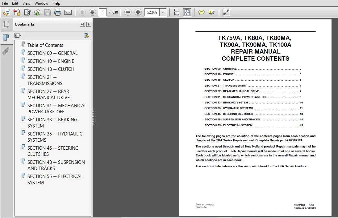
TABLE OF CONTENTS:
New Holland TK75VA TK80A TK80MA TK90A TK90MA TK100A Repair Manual
General Instructions 2
Important Notice 2
Shimming 2
Rotating Shaft Seals 2
O-Rings 2
Sealers 2
Bearings 2
Spring Pins 2
Precautionary Notice 3
Equipment Notice 3
Spare Parts Notice 3
General Notices 3
Health and Safety 4
Health and Safety Precautions 4
General Workshop Tools and Equipment 10
Legal Aspects 10
Lubricants and Greases 10
Precautionary Statements 11
Personal Safety 11
Machine Safety 11
Safety 12
The Tractor 12
Driving the Tractor 12
Operating the Tractor 12
Operating the PTO 13
Servicing the Tractor 13
Diesel Fuel 14
ROPS 14
Ecology and the Environment 15
Tightening Torques 16
Federal Emissions Warranty 18
California Emission Control Warranty Statement 19
Lubricants 21
3
SECTION 10 — ENGINE
BOOK 1 – 87582125
Chapter 1 — Engine
CONTENTS
Section Description Page
Specifications 4
Tightening Torques 24
Special Tools 26
Engine Cooling System Diagram 30
Troubleshooting 31
Engine Overhaul 35
Engine 35
Removal 35
Installation 38
Compression Test 39
Disassembly 40
Assembly 54
Mounting the Balancing Device with Counter-rotating Weights 54
Mounting the Tappets and Drive Shaft With Main Bearing Caps,
Bearings and Thrust Rings 55
Mounting the Rear Cover With Seal and Engine Flywheel 57
Seal Installation 59
Mounting the Pistons Complete With Rings, Pins, Connecting
Rods, Big End Caps and Bearings — Checking Protrusion In
Relation To Cylinder Block Face 60
Synchronizing the Timing Gears 61
Installing the Counter-rotating Weight Box to the Oil Sump 62
Installing the Bosch Injection Pump 63
Installing the Cylinder Head Gasket 64
Installing and Tightening the Cylinder Head 64
Valve / Rocker Arm Clearance Adjustment 65
Installing Fuel Injectors 65
Cooling System Belt Tension Adjustment 65
Checks, Measurements and Repairs of Components 66
Cylinder Block 66
Crankshaft, Main Bearings and Flywheel 68
Crankshaft 68
4
SECTION 10 — ENGINE
BOOK 1 – 87582125
Chapter 1 — Engine (Continued)
CONTENTS
Section Description Page
Bearings 70
Flywheel 71
Connecting Rods 72
Pistons 73
Camshaft, Tappets and Valves 76
Valves 76
Tappets 76
Camshaft 77
Cylinder Head 79
Valve Guides 80
Valve Seats In Cylinder Head 83
Injector Sleeves 84
Cylinder Head Bolts 85
Counterweight Balancer 86
Lubrication System Maintenance 87
Engine Oil Pump Servicing 87
Low Oil Pressure Indicator 88
Cooling System Maintenance 88
Radiator Servicing 88
Testing Cooling System Thermometer 89
Replacing the Thermostat 89
Drive Belts Tension Adjustment 89
Radiator 90
Removal 90
Installation 92
Crankshaft Front Oil Seal 93
Removal 93
Installation 96
Valve–Rocker Arm Clearance 97
Rear Fuel Tank 100
Removal 100
Installation 102
5
SECTION 10 — ENGINE
BOOK 1 – 87582125
Chapter 1 — Engine (Continued)
CONTENTS
Section Description Page
Front Fuel Tank 103
Removal 103
Installation 104
Injectors 105
Removal 105
Installation 106
Bosch Injection Pump 107
Removal 107
Installation 111
Timing 112
Air Bleeding 114
Timing Injection Pump Off the Tractor 115
Installing the Injection Pump Onto the Engine 120
Turbocharged Diesel Engine —
TK75VA, TK90A, TK90MA, TK100A Models 121
Exhaust Pipe 124
Removal 124
Installation 124
Coolant Pump 125
Removal 125
Installation 126
Disassembly 127
Assembly 127
Thermostatic Valve 128
Removal 128
Installation 129
Coolant Pump and Alternator Drive Belt 130
Tension Adjustment 130
6
SECTION 18 — CLUTCH
BOOK 1 – 87582125
Chapter 1 — Clutch
CONTENTS
Section Description Page
Specifications 2
Torque Settings 3
Special Tools 4
Sectional Views 7
Troubleshooting 8
Adjustments 9
Power Take-Off (PTO) Clutch 9
Lever Adjustment 9
Main Clutch 10
Lever Adjustment 10
Overhaul 11
Clutch 11
Removal 11
Installation 22
Dual Disk Clutch 11 5″ 24
Disassembly 24
Assembly 29
PTO Clutch Adjustment 30
Main Clutch Adjustment 31
7
SECTION 21 — TRANSMISSIONS
BOOK 1 – 87582125
Chapter 1 — 8 x 8 Transmission with Non-synchronized
Mechanical Shuttle
CONTENTS
Section Description Page
Specifications 2
Shuttle 2
Gearbox and Range Gear 2
Tightening Torques 3
Special Tools 5
Description and Operation 9
Sectional Views 9
Gearbox and Shuttle 12
Troubleshooting 12
Overhaul 13
Rear Transmission Housing — Gearbox 13
Disassembly 13
Assembly 18
Gearbox Driving Shaft Clearance Adjustment 21
SECTION 27 — REAR MECHANICAL DRIVE
BOOK 2 – 87582126
Chapter 1 — Rear Mechanical Drive
CONTENTS
Section Description Page
Specifications 2
Lateral Final Drives 2
Torque Settings 3
Special Tools 5
Description and Operation 10
Sectional Views 10
8
SECTION 27 — REAR MECHANICAL DRIVE
BOOK 2 – 87582126
Chapter 1 — Rear Mechanical Drive (Continued)
CONTENTS
Section Description Page
Troubleshooting 13
Bevel Gear 13
Final Drive 13
Overhaul 14
Rear Transmission-Gearbox Housing (Model TK75VA) 14
Removal–Installation 14
Rear Transmission-Gearbox Housing
(Models TK80A, TK90A, and TK100A) 34
Removal 34
Installation 49
Bevel Gear 51
Disassembly 51
Adjustments 51
Assembly 56
Left-Hand Final Drive Casing (Model TK75VA) 57
Removal–Installation 57
Left-Hand Final Drive Casing
(Models TK80A, TK90A, and TK100A) 68
Removal 68
Installation 75
Final Drive Driven Gear 77
Removal 77
Installation 78
9
SECTION 31 — MECHANICAL POWER TAKE-OFF
BOOK 2 – 87582126
Chapter 1 — Mechanical Power Take-Off System
CONTENTS
Section Description Page
Specifications 2
Torque Settings 3
Special Tools 4
Description and Operation 6
Sectional Views 6
Troubleshooting 8
Overhaul 8
Mechanical PTO 8
Removal 8
Installation 12
Disassembly 13
Assembly 15
10
SECTION 33 — BRAKING SYSTEM
BOOK 2 – 87582126
Chapter 1 — Braking System
CONTENTS
Section Description Page
Specifications 2
Tightening Torques 3
Special Tools 4
Sectional Views 7
Description and Operation 11
Service Brakes 11
Parking Brake 11
Troubleshooting 11
Adjustments 12
Brake Unit 12
Removal 12
Installation 13
Steering Clutch Right or Left-Hand Hub Seal 15
Removal 15
Installation 15
Braking Unit Hydraulic Actuator 16
Removal 16
Disassembly 18
Assembly 18
Installation 18
Pressure Adjustment for the Left or Right Brake
Actuator Assembly 18
11
SECTION 35 — HYDRAULIC SYSTEMS
BOOK 2 – 87582126
Chapter 1 — Rear Mechanical Hydraulic Lift
CONTENTS
Section Description Page
Specifications 2
Implement Hitching Device 4
Hydraulic Pump 4
Torque Settings 5
Special Tools 7
Description and Operation 9
Sectional Views 10
Lift Oil Flow 12
Troubleshooting 15
Hydraulic Lift (model TK75VA) 17
Removal–Refitting 17
Installation 24
Hydraulic Lift (models TK80A, TK90A, and TK100A) 26
Removal–Refitting 26
Installation 37
Disassembly 39
Assembly 42
Lift Adjustment 44
Rod Mechanism Adjustments 50
Lift Control Valve 53
Removal 53
Installation 57
Disassembly 58
Installation 62
12
SECTION 35 — HYDRAULIC SYSTEMS
BOOK 2 – 87582126
Chapter 2 — Auxiliary Control Valves
CONTENTS
Section Description Page
Specifications 2
Torque Settings 2
Sectional Views 3
Special Tools 6
Description and Operation 6
Lifting 9
Lowering 9
Float Operation 10
Overhaul 11
Auxiliary Control Valves 11
Removal 11
Installation 13
Disassembly 13
Assembly 15
Valve Leakage Test 16
Adjustment of the Automatic Detent Release Pressure 16
Flow Control Valve 17
Disassembly 17
Flow Control Adjustment 18
13
SECTION 46 — STEERING CLUTCHES
BOOK 2 – 87582126
Chapter 1 — Steering Clutches
CONTENTS
Section Description Page
Specifications 2
Torque Settings 4
Special Tools 5
Sectional Views 8
Description and Operation 12
Steering Clutches 12
Operation 12
Troubleshooting 12
Overhaul 13
Steering Clutches 13
Removal 13
Disassembly 13
Assembly 14
Installation 15
Steering Clutches Internal Control 16
Removal 16
Disassembly 16
Assembly 17
Installation 17
Steering Clutches Hydraulic Control Valve 18
Removal 18
Installation 19
Disassembly 20
Assembly 22
Steering Clutch Pressure Adjustment 23
14
SECTION 48 — SUSPENSION AND TRACKS
BOOK 3 – 87582127
Chapter 1 — Suspension and Tracks
CONTENTS
Section Description Page
Specifications 3
Tightening Torques 9
Special Tools 15
Sectional Views 16
Overhaul 21
Chains 21
Tension Adjustment 21
Removal 22
Installation 23
Shoes 24
Removal 24
Installation 24
Link 25
Removal 25
Installation 26
Front Suspension 27
Removal 27
Installation 27
Disassembly 28
Assembly 28
Rear Suspension 29
Removal 29
Installation 30
Chain Tightener Wheel 32
Removal 32
Installation 33
Chain Tightener Wheel with Bushings 34
Disassembly 34
Assembly 35
Chain Tightener Wheel with Ball Bearings 36
Disassembly 36
Assembly 37
15
SECTION 48 — SUSPENSION AND TRACKS
BOOK 3 – 87582127
Chapter 1 — Suspension and Tracks (Continued)
CONTENTS
Section Description Page
Chain Tightener Device 39
Removal 39
Installation 39
Disassembly 40
Assembly 40
Support Rollers 41
Removal 41
Installation 42
Disassembly 44
Assembly 45
Supporting Roller 46
Removal 46
Installation 46
Disassembly 47
Assembly 47
SECTION 55 — ELECTRICAL SYSTEM
BOOK 3 – 87582127
Chapter 1 — Instruments
CONTENTS
Section Description Page
Description and Operation 2
Analog Instrument Panel for Model TK75VA 2
Analog Instrument Panel for Model TK80A, TK90A, and TK100A 3
Fuel Gauge 4
Rev Counter 4
Engine Cooling Liquid Temperature Indicator 4
Transmitters, Sensors and Switches 5
16
SECTION 55 — ELECTRICAL SYSTEM
BOOK 3 – 87582127
Chapter 2 — Components
CONTENTS
Section Description Page
Description and Operation 2
Central Console Panel 2
Analog Control Panel 2
Hazard Warning Lights Switch 3
Lights/Horn Switch 3
Side/tail Lights 3
Dipped Beam Headlights 3
Full Beam Headlights 3
Horn 4
Swivel Lights Switch 4
Direction Indicators Switch 4
Central Console Controls 5
Starter Key Switch 5
Thermostart Pushbutton 5
Bulb Replacement 6
Front Head Lamp 6
Front Sidelight and Direction Indicator Lamp 7
Work Light Bulbs On Tractors With Roll Bar 7
Rear Sidelights, Brake and Direction Indicator Light 8
17
SECTION 55 — ELECTRICAL SYSTEM
BOOK 3 – 87582127
Chapter 3 — Starting System
CONTENTS
Section Description Page
Specifications 2
Tightening Torques 2
Description and Operation 3
System Testing 5
Starting System Test on Tractor 5
Current Absorbed on the Starter Motor Circuit 5
Starting System Circuit Resistance (Voltage Drop) 6
Positive Battery Cable 6
Starter Motor Ground Connections 6
Battery Ground Lead 6
Overhaul 7
Starter Motor 7
Installation 7
Assembly 8
Bench Tests 9
18
SECTION 55 — ELECTRICAL SYSTEM
BOOK 3 – 87582127
Chapter 4 — Charging System
CONTENTS
Section Description Page
Specifications 2
Torque Settings 2
Description and Operation 3
System Testing and Troubleshooting 5
Precautions 5
Preliminary Checks 5
Preliminary Tests 5
Alternator Wire Connection Tests 6
Alternator Charging Current and Regulated Voltage 6
Voltage Drops in the Alternator Charging Circuit 7
Alternator Component Tests 8
Overhaul 9
Alternator 9
Removal 9
Testing Before Disassembly 10
Rotor and Regulator Field Circuit Test 10
Checking the Continuity of Three Stator Windings 11
Checking the Diodes 12
Excitation Diodes Test 12
Positive Power Diode Tests 13
Negative Power Diode Tests 13
Rotor 13
Check on Rotor Winding Resistance Measured Between
Pins Connected to Brushes 13
Disassembly 14
Assembly 17
Repair 17
Installation 17
19
SECTION 55 — ELECTRICAL SYSTEM
BOOK 3 – 87582127
Chapter 5 — Battery
CONTENTS
Section Description Page
Specifications 2
Description and Operation 2
Overhaul 3
Battery 3
Removal 3
Installation 3
Battery Maintenance 4
Relative Density 4
Battery Servicing 4
Dry-charged Batteries 5
Charging the Battery 5
Normal charging (Top Off) 5
Charging Extremely Flat Batteries 5
Battery Testing 6
Performance Test 6
Battery Problems — Causes 7
SECTION 55 — ELECTRICAL SYSTEM
BOOK 3 – 87582127
Chapter 6 — Electrical Circuits
CONTENTS
Section Description Page
Electrical Circuit Components 3
Location of Components 5
Main Wiring 7
Fuses and Relays 8
Fusebox 8
Relays 10
Symbols Used In Electrical Circuits 11
20
SECTION 55 — ELECTRICAL SYSTEM
BOOK 3 – 87582127
Chapter 6 — Electrical Circuits (Continued)
CONTENTS
Section Description Page
Wire Color Coding 12
Wiring Diagrams and Connections Identification Code 12
Connectors 13
Electrical Circuits 17
Starter and Recharging Circuit 19
Operator Safety Circuit 26
Sensors And Transmitters Circuit 32
Horn, Power Socket and Seven Pole Coupling Circuit 37
Diagnostics 43
Power Supply — Battery 44
Starter Motor 45
Starter Switch 49
Thermostarter Push-Button 50
Engine Stop Electromagnet 52
Alternator 54
Operator Safety Circuit 57
Horn and Power Socket 62
Tale/Side Lights 64
Number Plate Light 67
Dipped Beam Headlights 68
Full Beam Headlights 70
Full Beam Headlights Indicator Lamp 72
Hazard and Direction Indicator Lights 73
Swivel Position Lights 77
Work Lights 79
Instruments 80
Engine Coolant Temperature Sensor 82
Fuel Level Transmitter 84
Engine Oil Pressure Sensor 86
Air Filter Clogged Sensor 88
Water Sediment in Fuel Filter Sensor 90
Checking Procedure for Sensors and Transmitters Circuits to Ground 92
NEW HOLLAND TK75VA TK80A TK80MA TK90A TK90MA TK100A REPAIR MANUAL 87582124 – PDF DOWNLOAD:
IMAGES PREVIEW OF THE MANUAL:
PLEASE NOTE:
- This is not a physical manual but a digital manual – meaning no physical copy will be couriered to you. The manual can be yours in the next 2 mins as once you make the payment, you will be directed to the download page IMMEDIATELY.
- This is the same manual used by the dealers inorder to diagnose your vehicle of its faults.
- Require some other service manual or have any queries: please WRITE to us at [email protected]