New Holland Tractor TD75D TD95D TD95D High Clearance Service Manual – PDF DOWNLOAD
Original price was: $68.95.$37.95Current price is: $37.95.
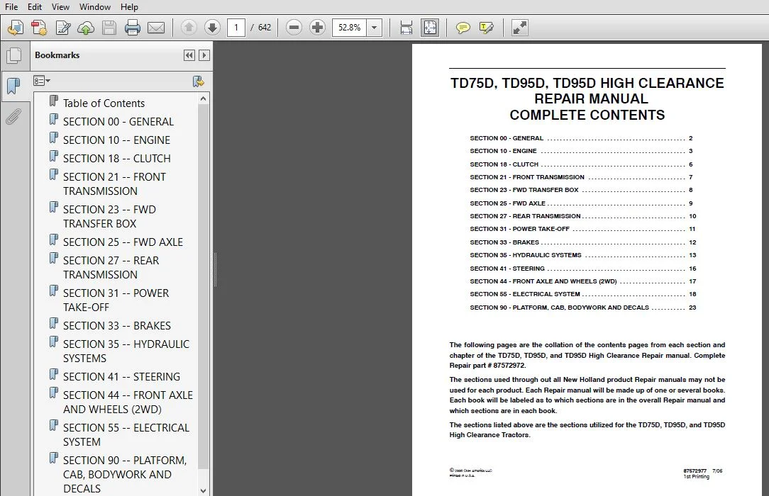
New Holland Tractor TD75D TD95D TD95D High Clearance Service Manual
Part No: 87572972
Description
New Holland Tractor TD75D TD95D TD95D High Clearance Service Manual
FILE DETAILS:
New Holland Tractor TD75D TD95D TD95D High Clearance Service Manual
Size: 39.5 MB
Format: PDF
Language: English
Number of Pages: 642 pages
Brand: New Holland
Type of machine: Tractor
Type of document: Repair Manual
Model: TD75D TD95D TD95D High Clearance
Part No: 87572972
DESCRIPTION:
New Holland Tractor TD75D TD95D TD95D High Clearance Service Manual
GENERAL INSTRUCTIONS:
IMPORTANT NOTICE:
All maintenance and repair operations described in this manual should be carried out exclusively by the authorized workshops. All instructions detailed should be carefully observed and special equipment indicated should be used if necessary. Everyone who carries out service operations described without carefully observing these directives will be directly responsible for resulting consequences.
SHIMMING:
At each adjustment, select adjusting shims, measure them individually using a micrometer and then sum up recorded values. Do not rely on measuring the whole shimming set, which may be incorrect, or on the rated value indicated for each shim.
ROTATING SHAFT SEALS:
To correctly install rotating shaft seals, observe the following instructions:
• Let the seal soak into the same oil as it will seal for at least half an hour before mounting;
• Thoroughly clean the shaft and ensure that the shaft working surface is not damaged;
• Place the sealing lip towards the fluid. In case of a hydrodynamic lip, consider the shaft rotation direction and orient grooves in order that they
deviate the fluid towards the inner side of the seal;
• Coat the sealing lip with a thin layer of lubricant (oil rather than grease) and fill the gap between the sealing lip and the dust lip of double lip seals
with grease;
• Insert the seal into its seat and press it down using a flat punch. Do not tap the seal with a hammer or a drift;
• Take care to insert the seal perpendicular to its seat while you are pressing it. Once the seal is settled, ensure that it contacts the thrust element,
if required;
• To prevent damaging the sealing lip against the shaft, place a suitable protection during installation.
O RINGS:
Lubricate the O rings before inserting them into their seats. This will prevent the O rings from roll over and twisting during mounting, which will jeopardize sealing.
SEALERS:
Apply silicone/gasket eliminator over the mating surfaces marked with an X. Before applying the sealer, prepare the surface as follows:
• remove possible scales using a metal brush;
• thoroughly degrease the surfaces using one of the following cleaning agents: trichlorethylene, diesel fuel or a water and soda solution.
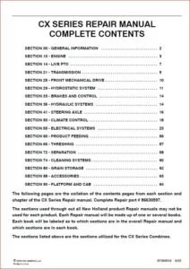
TABLE OF CONTENTS:
New Holland Tractor TD75D TD95D TD95D High Clearance Service Manual
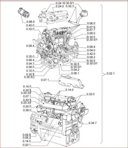
SECTION 10 — ENGINE
BOOK 1 – 87572973
Chapter 1 — Engine
CONTENTS
Section Description Page
Specifications 2
Special Tools 10
Tightening Torques 14
Sectional Views 15
Troubleshooting 17
Overhaul 21
10 001 10 Engine 21
Removal 21
10 001 54 Installation 33
Disassembly 35
Assembly 50
Compression Test 60
Checks, Dimensions, and Repairs 61
Cylinder Block 61
Crankshaft, Main Bearings, and Flywheel 63
Connecting Rods 67
Pistons 68
Valves 71
Tappets 71
Camshaft 72
Valve Timing Check 73
Cylinder Head 74
10 102 70 Rotating Counterweight Dynamic Balancer 75
Valve Guides 76
Valve Seats in Cylinder Head 79
Crankshaft Front Oil Seal 80
Valve Clearance 86
4
SECTION 10 — ENGINE
BOOK 1 – 87572973
Chapter 2 — Cooling System
CONTENTS
Section Description Page
Specifications 2
Special Tools 3
Sectional Views 4
Description and Operation 5
Cooling System 5
Radiator 5
Thermometer 5
Thermostat 5
Thermostatic Switch 5
Overhaul 6
10 406 10 Water Pump 6
Removal 6
Disassembly 9
Assembly 9
Installation 10
10 402 30 Cooling System Thermostat 10
Removal 10
Installation 13
10 402 28 Radiator 14
Removal 14
Installation 17
5
SECTION 10 — ENGINE
BOOK 1 – 87572973
Chapter 3 — Lubrication System
CONTENTS
Section Description Page
Specifications 2
Special Tools 3
Sectional Views 4
Description and Operation 5
Oil Filter 5
Low Oil Indicator 5
10 001 10 Oil Pump 6
SECTION 10 — ENGINE
BOOK 1 – 87572973
Chapter 4 — Fuel System
CONTENTS
Section Description Page
Specifications 2
Special Tools 4
Tightening Torques 5
Description and Operation 6
Fuel Injection Pump (Bosch) 6
Turbocharged Models 6
All Models 8
Overhaul 10
10 218 30 Fuel Injectors 10
Removal 10
Installation 11
Fuel Injector Sleeves 12
Checking Injector Protrusion 12
Removal 12
Installation 13
10 246 14 Injection Pump 14
Removal 14
Installation 18
Checking the Fuel Injection Pump Timing with the Pump on the Tractor 19
Lock-time the Fuel Injection Pump with the Pump Removed from the Tractor 23
Fuel System Air Bleeding 28
6
SECTION 18 — CLUTCH
BOOK 2 – 87572974
Chapter 1 — Clutch
CONTENTS
Section Description Page
Specifications 2
Clutches 2
Main Clutch (11 in /11 in ) (Model TD75D) 2
Main Clutch (12 in /12 in ) (Model TD95D) 3
Tightening Torques 4
Special Tools 4
Sectional Views 5
Valeo Clutches (11 in /11 in and 12 in /12 in ) 5
Luk Clutches (11 in /11 in and 12 in /12 in ) 6
Troubleshooting 7
Overhaul 8
11 in /11 in and 12 in /12 in Clutches 8
Removal 8
Installation 15
Disassembly 16
Assembly 19
Checks, Measurements and Repairs 20
Dimensions of the Valeo 11 in /11 in Dual Clutch 20
Dimensions of the Luk 11 in /11 in Dual Clutch 20
Dimensions of the Valeo 12 in /12 in Dual Clutch 20
Dimensions of the Luk 12 in /12 in Dual Clutch 20
Minimum Permissible Dimensions After Refacing 11 in /11 in and
12 in /12 in Dual Clutches 20
Valeo 11 in Flywheel 21
Luk 11 in Flywheel 21
Valeo 12 in Flywheel 21
Luk 12 in Flywheel 21
Clutch Release Lever Coplanarity Adjustment 22
Main Clutch Control Linkage Adjustment 23
PTO Clutch Linkage Adjustment 23
7
SECTION 21 — FRONT TRANSMISSION
BOOK 2 – 87572974
Chapter 1 — 12 x 12 Transmission with Synchronized Mechanical Shuttle
CONTENTS
Section Description Page
Specifications 2
Synchronizer Reverser 2
Gearbox/Reduction Unit 2
Torque Values 3
Special Tools 4
Sectional Views 4
Description and Operation 6
Synchronizer Reverser Troubleshooting 6
Overhaul 7
Clutch–Reverser Casing 7
Disassembly 7
Assembly 11
SECTION 21 — FRONT TRANSMISSION
BOOK 2 – 87572974
Chapter 2 — 20 x 12 Transmission with
Synchronized Mechanical Shuttle and Creeper
CONTENTS
Section Description Page
Specifications 2
Synchronizer Reverser–Creeper Unit 2
Creeper Unit 2
Gearbox 2
Torque Values 3
Special Tools 4
Sectional Views 5
Description and Operation 7
Troubleshooting — Synchronizer Reverser–Creeper Unit 7
Overhaul 8
Clutch Casing–Synchronizer Reverser and Creeper Unit 8
Disassembly 8
Assembly 13
8
SECTION 23 — FWD TRANSFER BOX
BOOK 2 – 87572974
Chapter 1 — FWD Transfer Box
CONTENTS
Section Description Page
Specifications 2
Drive Shaft 2
Tightening Torques 3
Special Tools 3
Description and Operation 4
Sectional Views 4
Overhaul 5
Transmission Shafts and Guard 5
Removal 5
Installation 5
Drive Gear Housing Assembly 6
Removal 6
Installation 7
Transfer Box, Unit Removed 8
Disassembly 8
Assembly 9
9
SECTION 25 — FWD AXLE
BOOK 2 – 87572974
Chapter 1 — Front Mechanical Axle
CONTENTS
Section Description Page
Specifications 2
Tightening Torques 4
Special Tools 6
Description of Operation 7
Sectional Views 7
Overhaul 10
Complete Front Axle Assembly 10
Removal 10
Installation 13
Disassembly 14
Assembly 21
Steering Knuckle Pins and Bearings 22
Replacement 22
Wheel Hub Seal Replacement 23
Limited–Slip Differential 24
Operation 24
Removal 24
Disassembly 25
Assembly 25
Adjustments 26
Steering Knuckle 26
Wheel Hub Bearing 28
Bevel Drive Adjustments 29
Front Axle Differential 29
Determining Pinion Shaft Pre-load Shim Thickness 30
Determining Pinion Shaft Position Shim Thickness 31
Pinion Shaft Installation and Pre-load Check 33
Differencial Installation and Backlash Adjustment 34
Differential Bearing Pre-load Adjustment 35
Sealing Compound Application 36
Toe-In Adjustments 37
10
SECTION 27 — REAR TRANSMISSION
BOOK 2 – 87572974
Chapter 1 — Rear Axle and Transmission
CONTENTS
Section Description Page
Specifications 2
Tightening Torques 4
Special Tools 6
Description of Operation 7
Sectional Views 7
Troubleshooting 10
Pinion and Differential 10
Final Drives 10
Overhaul 11
Rear Axle Transmission — Gearbox Case 11
Removal 11
Installation 28
Transmission–Gearbox Case 29
Disassembly 29
Assembly 33
Adjustments 36
Gearbox Driving Shaft Axial Clearance 36
Differential Lock Engagement Sleeve Position Adjustment 37
Pinion Shaft Positioning Adjustment Ring 38
Taper–Roller Bearings for Pinion Shaft 40
Differential Bearings and Backlash of Ring and Pinion Teeth 41
Differential Planetary and Side Gear Backlash 43
11
SECTION 31 — POWER TAKE-OFF
BOOK 3 – 87572975
Chapter 1 — Power Take-Off
CONTENTS
Section Description Page
Specifications 2
Special Tools 3
Tightening Torques 4
Description of Operation 5
Sectional Views 5
Troubleshooting 8
Overhaul 9
Mechanical PTO 9
Removal 9
Installation 11
540 RPM PTO 12
Disassembly 12
Assembly 14
540/1000 RPM PTO 15
Disassembly 15
Assembly 20
12
SECTION 33 — BRAKES
BOOK 3 – 87572975
Chapter 1 — Brakes
CONTENTS
Section Description Page
Specifications 2
Tightening Torques 3
Description of Operation 4
Sectional Views 4
Service Brake 6
Parking Brake 6
Special Tools 6
Troubleshooting 7
Overhaul 8
Right Hand or Left Hand Brake (Service Brakes) 8
Removal 8
Installation 11
Adjustments 13
Height of Service Brake Pedals 13
Hand Brake Control Travel 14
13
SECTION 35 — HYDRAULIC SYSTEMS
BOOK 3 – 87572975
Chapter 1 — Hydraulic Systems
CONTENTS
Operation Description Page
Precautionary Statements 2
Description and Operation 3
Hydraulic Oil Specification 5
Hydraulic System Configuration 5
Hydraulic System Diagrams 6
Hydraulic Diagram On TD75D and TD95D Models 6
Hydraulic Diagram On TD95D High Clearance Models 7
Auxiliary Control Valve Oil Flow 8
Double-Acting Cylinder Lift Phase 8
Double-Acting Cylinder Lower Phase 8
Single-Acting Cylinder Lift Phase 8
Single-Acting Cylinder Lower Phase 9
Double-Acting Cylinder with Automatic Detent Release Lift Phase 9
Double-Acting Cylinder with Automatic Detent Release Lower Phase 10
Rear Remote Valve Control Levers 10
Control Lever Positions 11
Quick-Release Couplers 11
Switching Between Single and Double Acting Cylinders 12
Mechanically Controlled Hydraulic Lift 12
Fast Raise/Lower Control Device 12
Principles of Draft Control 13
Principles of Position Control 13
Principles of Float 14
Principles of Draft and Position Control Combined 14
Hydraulic Lift Valve Oil Flow 15
Hydraulic Lift Oil Flow (Lift Phase) 15
Hydraulic Lift Oil Flow (Neutral Phase) 16
Hydraulic Lift Oil Flow (Lowering Phase) 17
Three-Point Hitch (Category I and II) 18
Adjustable Length Top Link 18
Right-Hand Lift Rod 18
Telescopic Lateral Stabilizer Struts 19
Lower Links 19
Left-Hand Lift Rod 20
14
SECTION 35 — HYDRAULIC SYSTEMS
BOOK 3 – 87572975
Chapter 2 — Hydraulic System Overhaul
CONTENTS
Operation Description Page
Specifications 3
Tightening Torques 8
Special Tools 9
Sectional Views 10
Troubleshooting 13
Overhaul 15
Mechanically Controlled Hydraulic Lift 15
Removal 15
Installation 21
Disassembly 22
Assembly 24
Adjustments 27
Position Control 27
Lift Arms Maximum Height 28
Draft Control 29
Position Control Linkage 33
Draft Control Linkage 33
Fast Raise/Lower Control Device 34
Lift Pressure Relief Valve 35
Installation 35
Calibration 35
Lift Control Valve Block 37
Disassembly 37
Assembly 41
High-pressure (Lift) Pump 42
Disassembly 42
Inspection and Repair 42
Assembly 43
15
SECTION 35 — HYDRAULIC SYSTEMS
BOOK 3 – 87572975
Chapter 2 — Hydraulic System Overhaul (Continued)
CONTENTS
Operation Description Page
Convertible Single/Double Acting Auxiliary Control Valve 44
Disassembly 44
Assembly 44
Convertible Single/Double Acting Auxiliary Control Valve with Float Control
and Detent Release 45
Disassembly 45
Assembly 51
Spool Binding Test 52
Spool Leakage Test 53
Auxiliary Control Valve Leakage Test 53
Adjustment of the Auxiliary Control Valve Automatic Detent Release Pressure 54
16
SECTION 41 — STEERING
BOOK 3 – 87572975
Chapter 1 — Steering
CONTENTS
Operation Description Page
Specifications 2
Hydraulic Pump C25 3
Torque Settings 4
Special Tools 4
Components 5
Troubleshooting 6
Description and Operation 10
Hydrostatic Power Steering (2WD) 10
Hydrostatic Power Steering (FWD) 12
Operation 14
Steering Right 14
Steering Left 14
Manual Steering to Right 14
Manual Steering to Left 14
41 204 30 Hydrostatic Steering Control Valve 15
Removal 15
Installation 18
41 204 34 Disassembly 19
Assembly 24
41 204 38 Steering Control Valve Testing 33
41 206 20 Hydrostatic Steering Pump 36
Disassembly 36
Assembly 36
41 216 20 Steering Cylinder (2WD) 37
Removal 37
Installation 37
Steering Cylinder (FWD) 38
Removal 38
17
SECTION 44 — FRONT AXLE AND WHEELS (2WD)
BOOK 4 – 87572976
Chapter 1 — Axle and Wheels
CONTENTS
Section Description Page
Specifications 2
Tightening Torques 5
Special Tools 6
Troubleshooting 6
Overhaul 7
Front Axle 7
Removal 7
Installation 9
Axle Wheel Hub 10
Removal 10
Installation 12
Stub Axle 13
Removal 13
Installation 15
Adjustments 17
Toe-in 17
18
SECTION 55 — ELECTRICAL SYSTEM
BOOK 4 – 87572976
Chapter 1 — Instrument Cluster
CONTENTS
Section Description Page
Instrument Cluster Description 2
Analog Instrument Panel 2
Warning and Indicator Lights 3
Fuel Level Gauge 4
Tachometer and Hourmeter 4
Engine Coolant Temperature Gauge 4
SECTION 55 — ELECTRICAL SYSTEM
BOOK 4 – 87572976
Chapter 2 — Components
CONTENTS
Section Description Page
Electrical Components Description 2
Instrument Console Controls 2
Lights Control Lever 2
Rear Hood Controls 2
Starter Switch 2
Cab Controls 3
Fender Mounted Controls 3
Heating and Air Conditioning Controls 4
Radio (where applicable) 4
Applicable Components, Sensors and Switches 5
Description 5
Locations 6
19
SECTION 55 — ELECTRICAL SYSTEM
BOOK 4 – 87572976
Chapter 3 — Starting System
CONTENTS
Section Description Page
Specifications 2
Tightening Torques 2
Description and Operation 3
Overhaul 5
Starting System Test on Tractor 5
Power Absorption in Starter Motor Circuit 5
Resistance in Ignition System Circuit (Voltage Drop) 6
Battery Positive Cable Check 6
Starter Motor Ground Lead Check 7
Battery Ground Cable Check 7
55 201 50 Starter Motor 7
Removal 7
Installation 7
55 201 54 Disassembly 8
Assembly 9
Starter Motor Tests and Inspections 9
Armature Shaft End-Play 9
Starter Motor Test Without Load 10
Armature 10
Field Windings 11
Bearing Bushings 11
Driving Pinion 11
20
SECTION 55 — ELECTRICAL SYSTEM
BOOK 4 – 87572976
Chapter 4 — Charging System
CONTENTS
Section Description Page
Specifications 2
Tightening Torques 2
Description and Operation 3
Troubleshooting 5
Precautions 5
Preliminary Checks 5
Tests and Checks 6
Alternator Wire Connections 7
Charging Current and Regulated Voltage 8
Charging Circuit Voltage Drop 9
Alternator Maximum Output 10
Alternator Component Tests 11
Overhaul 12
Alternator 12
Removal 12
Disassembly 13
Alternator Component Testing 14
Assembly 21
Repair 21
Installation 22
21
SECTION 55 — ELECTRICAL SYSTEM
BOOK 4 – 87572976
Chapter 5 — Battery
CONTENTS
Section Description Page
Specifications 2
Troubleshooting 2
Description and Operation 3
Overhaul 4
Battery 4
Removal 4
Installation 4
Battery Maintenance 5
Relative Density 5
Precautions 5
Dry-Charged Batteries 6
Charging the Battery 6
Normal Charging (Top Up) 6
Charging Very Flat Batteries 6
Testing 7
22
SECTION 55 — ELECTRICAL SYSTEM
BOOK 4 – 87572976
Chapter 6 — Electrical Circuits
CONTENTS
Section Description Page
Description and Operation 2
Electrical Diagram Symbols 2
Wire Color Coding 3
Fuse Box/Fuses 4
Main Wiring Diagrams (Cab or ROPS) 5
Diagrams A, B, C and D 5
Diagram A (Main Harness) 8
Diagram B (Dash Harness) 10
Diagram C (Rear Harness) 12
Diagram D (Cab/Platform Harness) 14
Individual Circuits 16
Start-up Circuit 16
High and Low Beam Headlights, Cornering and Parking Lights 18
Direction Indicators and Hazard Lights Circuit 20
Work Lamp Circuit 22
Operators Presence Circuit 24
Analog Instrument Circuit 26
Heating and Air-Conditioning System Circuit 27
23
SECTION 90 — PLATFORM, CAB, BODYWORK AND DECALS
BOOK 4 – 87572976
Chapter 1 — Cab
CONTENTS
Section Description Page
Overhaul 2
Control Levers, Seat, Electrical Controls 2
Disassembly 2
Assembly 9
Rear Window, Handle and Lock 10
Disassembly 10
Assembly 10
Lock and Exterior Handle 11
Disassembly 11
Assembly 11
LH Door 12
Disassembly 12
Assembly 12
Front Wiper Motor 13
Disassembly 13
Assembly 14
Cab Windows 15
Removal 15
Installation 16
24
SECTION 90 — PLATFORM, CAB, BODYWORK AND DECALS
BOOK 4 – 87572976
Chapter 2 — Air Conditioning System
CONTENTS
Section Description Page
Safety 3
Specifications 4
Special Tools 5
Description of Operation 6
Cab Heating and Ventilation Controls 8
Ventilation 8
Fan 8
Air Filter 8
Heating 9
Temperature Control Knob 9
Ignition Switch 9
Switching on the Air Conditioning and Temperature Control 10
Air Conditioning and Temperature Control Button 10
Heating Control Knob 10
3–Speed Fan Control Knob 10
Use of the Air Conditioning System 11
Switching On the Air Conditioning 11
Adjustment 11
Switching Off the Air Conditioning System 11
Main Components of the Air Conditioning System 12
SANDEN SD 7H15 Compressor 12
Condenser 13
Receiver/Dryer 13
Thermostatic Expansion Valve 14
Air Conditioner Temperature Cycling Control Switch 15
Thermostatic Switch (ANTIFROST) 15
Evaporator 16
Low Pressure Cut-out Switch 17
Combined High/Low Pressure Cut–out Switch 17
System Pressure Relief Valve 17
Condenser 18
Receiver/Dryer 18
25
SECTION 90 — PLATFORM, CAB, BODYWORK AND DECALS
BOOK 4 – 87572976
Chapter 2 — Air Conditioning System (Continued)
CONTENTS
Section Description Page
Refrigerant Recovery–Recycling and Evacuation–
Charging Stations 19
Air Conditioning System 21
Function Testing of Cab Air Conditioning System 26
Summary of the Air Conditioning System Charging Operations 27
Checking for Refrigerant Leaks Using an Electronic Leak Detector 29
Maintenance of the Air Conditioning System 31
Troubleshooting 32
Overhaul 36
Air Conditioning and Heating Pipes 36
Removal 36
Installation 39
Receiver–Dryer 40
Removal 40
Installation 41
Condenser 42
Removal 42
Installation 42
Compressor 43
Removal 43
Installation 44
Compressor Oil — Type and Quantity 44
Adjustments 45
Compressor Drive Belt 45
Tension Adjustment 45
Fitting the Compressor Drive Belt 45
Checking Compressor Drive Belt Tension 45
Periodic Checking of Drive Belt 45
NEW HOLLAND TRACTOR TD75D TD95D TD95D HIGH CLEARANCE SERVICE MANUAL – PDF DOWNLOAD:
IMAGES PREVIEW OF THE MANUAL:
![]()
![]()
![]()
PLEASE NOTE:
- This is the SAME manual used by the dealers to troubleshoot any faults in your vehicle. This can be yours in 2 minutes after the payment is made.
- Contact us at [email protected] should you have any queries before your purchase or that you need any other service / repair / parts operators manual.