New Holland Tractor TT4.55, TT4.65, TT4.75 Service Manual 47969434 – PDF DOWNLOAD
Original price was: $54.95.$36.95Current price is: $36.95.
New Holland Tractor TT4.55, TT4.65, TT4.75 Service Manual
Part No: 47969434
Description
New Holland Tractor TT4.55, TT4.65, TT4.75 Service Manual
FILE DETAILS:
New Holland Tractor TT4.55, TT4.65, TT4.75 Service Manual
Size: 63.2 MB
Format: PDF
Language: English
Number of Pages : 809 pages
Brand: New Holland
Type of document: Service Manual
Model: TT4.55, TT4.65, TT4.75
Part No: 47969434
DESCRIPTION:
New Holland Tractor TT4.55, TT4.65, TT4.75 Service Manual
Engine – Overview DESCRIPTION AND OPERATION:
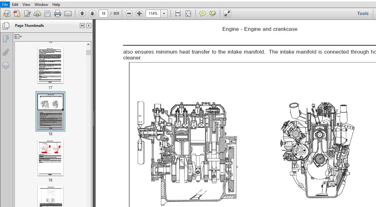
The engine is a 3 cylinder engine with Turbo Charger and a inter‐cooler. This engine features cross flow cylinder heads, with the inlet and exhaust manifolds on opposite sides of the cylinder head. The fuel and air combustion process, takes place in the specially designed bowel in the crown of the pistons
CYLINDER HEAD ASSEMBLY:
The cylinder head consists of valves and springs, with the valve rocker arm shaft assembly bolted to the cylinder block through the cylinder head. Cylinder head retaining bolts are evenly spaced with a six‐ point pattern around each cylinder; this ensures an even clamping load across the cylinder head. The intake and exhaust manifolds are bolted to the head; the intake manifold is mounted on the right side of the engine, with the diesel injectors mounted outside the rocker cover. The exhaust manifold is mounted on the left side of the engine. Water outlet connections and thermostat being attached to the front of the cylinder block directly behind the radiator Valve guides are inserted into the cylinder head, and replaceable. Special replaceable cast alloy valve seats are pressed into each valve port during manufacturing. No oversize valve seats on guides are available. All valves are fitted with positive value rotators; valve clearance is maintained by adjustment of the self locking adjusting screw, mounted in each of the rocker arms.
CAMSHAFT ASSEMBLY:
- The camshaft runs in 3 replaceable bushes. The camshaft drive gear is in mesh with and driven by the camshaft idler gear which is driven by the crankshaft timing gear. Camshaft end thrust is controlled by a thrust plate bolted to the block, and located between the camshaft gear and the front camshaft journal.
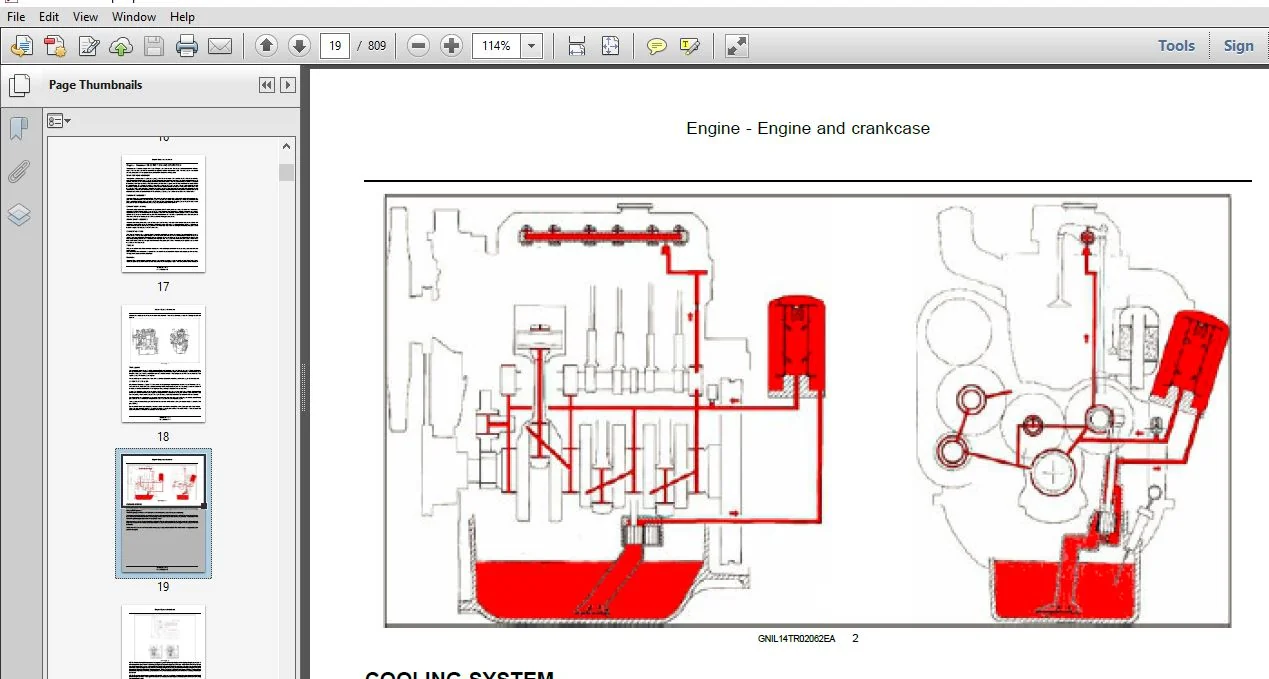
- A helical gear is integral on rear of cam shaft, and drives the engine oil lubrication pump mounted forward of the flywheel. Cylinder block assembly The cylinder block is an alloy cast iron with deep cylinder skirts & water jackets for cooling the cylinders. The cylinder bores are machined integral with the cylinder block, during the manufacturing process. Cylinders are inline and vertical and numbered from 1 to 3 from front of the engine to the rear.
- The oil sump, which is attached to the bottom of the cylinder block, is the reservoir for the engine oil lubrication system. A cast iron engine front cover and front plate is attached to the front of the engine and covers all of the timing gear assembly.
CRANKSHAFT ASSEMBLY:
The crankshaft is supported in the cylinder block by 4 main bearings. The crankshaft is manufactured from steel with machined finished crank webs, End thrust is controlled by a thrust bearing. A dynamic balancer is fitted and driven by crankshaft to ensure smooth running operation. Front and rear crankshaft oil sealing is affected by one piece seals that are designed for long and durable service life.
CONNECTING RODS:
The “Wedge” shaped at the small end of the connecting rod has been designed to reduce the reciprocating weight at the piston end. The connecting rods have a heavy beam construction and are assembled as a matched set to each engine. They are attached to the crankshaft, by means of insert type bearings. They are retained in position by the connecting rod big end cap and secured by two bolts per rod. The small end of the connecting rod is fitted with a replaceable bronze bushing, through which the free floating piston pin is fitted. The steel pin being held in place within the piston by two snap rings.
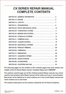
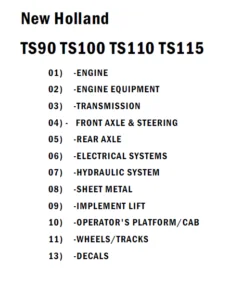
TABLE OF CONTENTS:
New Holland Tractor TT4.55, TT4.65, TT4.75 Service Manual
Engine 10
[10001] Engine and crankcase 101
[10102] Pan and covers 102
[10106] Valve drive and gears 103
[10101] Cylinder heads104
[10105] Connecting rods and pistons105
[10103] Crankshaft and flywheel106
[10210] Lift pump and lines 107
[10206] Fuel filters108
[10218] Fuel injection system 109
[10202] Air cleaners and lines 1010
[10250] Turbocharger and lines 1011
[10400] Engine cooling system1012
[10414] Fan and drive 1013
[10310] Aftercooler 1014
[10304] Engine lubrication system 1015
[10408] Oil cooler and lines 1016
Clutch 18
[18110] Clutch and components 181
Transmission 21
[21114] Mechanical transmission211
[21112] Power shuttle transmission 212
[21110] Master clutch housing 213
[21134] Power shuttle transmission external controls 214
[21154] Power shuttle transmission internal components215
[21120] Gearbox 216
47969434 28/11/2016
[21126] Gearbox external controls 217
[21145] Gearbox internal components 218
[21160] Creeper 219
[21162] Reverser 2110
[21168] Hi-Lo unit 2111
[21200] Dropbox2112
Front axle system 25
[25100] Powered front axle 251
[25102] Front bevel gear set and differential 252
[25108] Final drive hub, steering knuckles, and shafts 253
[25400] Non-powered front axle 254
Rear axle system 27
[27100] Powered rear axle 271
[27106] Rear bevel gear set and differential 272
[27120] Planetary and final drives 273
Power Take-Off (PTO) 31
[31114] Two-speed rear Power Take-Off (PTO)311
Brakes and controls 33
[33120] Mechanical service brakes 331
[33202] Hydraulic service brakes332
[33110] Parking brake or parking lock333
Hydraulic systems 35
[35000] Hydraulic systems 351
[35104] Fixed displacement pump 352
[35204] Remote control valves 353
[35100] Main lift system 354
Steering 41
[41101] Steering control 411
47969434 28/11/2016
[41200] Hydraulic control components 412
[41216] Cylinders 413
Wheels 44
[44511] Front wheels 441
Electrical systems 55
[55000] Electrical system 551
[55100] Harnesses and connectors 552
[55201] Engine starting system 553
[55301] Alternator554
[55302] Battery 555
[55640] Electronic modules 556
[55404] External lighting 557
[55408] Warning indicators, alarms, and instruments 558
Platform, cab, bodywork, and decals 90
[90118] Protections and footboards 901
[90114] Operator protections 902
[90120] Mechanically-adjusted operator seat 903
[90100] Engine hood and panels904
[90116] Fenders and guards905
NEW HOLLAND TRACTOR TT4.55, TT4.65, TT4.75 SERVICE MANUAL 47969434 – PDF DOWNLOAD:
IMAGES PREVIEW OF THE MANUAL:
PLEASE NOTE:
- This is the same manual used by the DEALERSHIPS to SERVICE your vehicle.
- The manual can be all yours – Once payment is complete, you will be taken to the download page from where you can download the manual. All in 2-5 minutes time!!
- Need any other service / repair / parts manual, please feel free to contact us at heydownloadss @gmail.com . We may surprise you with a nice offer