Nihon Kohden BSM-9510 Life Scope M Bedside Monitor Service Manual PDF
Original price was: $95.00.$30.95Current price is: $30.95.
Official Nihon Kohden BSM-9510 Life Scope M Bedside Monitor service manual covering models BSM-9510J and BSM-9510K. This comprehensive Nihon Kohden BSM-9510 repair guide includes troubleshooting, diagnostic checks, board/unit descriptions, disassembly & assembly procedures, maintenance checklists, adjustments, replaceable parts list, and full connector pin assignments — essential for biomedical engineers and qualified hospital service technicians.
Description
Nihon Kohden BSM-9510 Life Scope M Bedside Monitor Service Manual PDF DOWNLOAD
Description
Nihon Kohden BSM-9510 Life Scope M — Official Service Manual
This is the official Nihon Kohden BSM-9510 Life Scope M Bedside Monitor service manual, covering both BSM-9510J and BSM-9510K variants and all associated modules. Written for qualified biomedical service engineers and hospital-based technicians, this Nihon Kohden BSM-9510 repair guide provides the complete technical reference needed to troubleshoot, diagnose, maintain, and repair this multi-parameter ICU patient monitor — including full ECG, SpO2, NIBP, IBP, Temperature, CO2, FiO2, and Cardiac Output monitoring capabilities.
📋 File Details
| Detail | Info |
|---|---|
| Manual Name | Life Scope M Bedside Monitor Service Manual |
| Models Covered | BSM-9510J, BSM-9510K |
| Modules Covered | MU-950RJ/RK, AY-900PA, AY-910PA, AA-900PA, WS-920PA, RY-002PA, EK-900P |
| Document No. | 0634-001352 |
| Year | 2001 |
| PDF Quality | Clean searchable digital PDF |
| Total Pages | 119 |
📐 BSM-9510 Key Technical Specifications
Main Unit — MU-950RJ/RK
| Specification | Detail |
|---|---|
| Display Size | 10.4-inch LCD |
| Display Resolution | 640 × 480 dots |
| Viewing Area | 211 × 158 mm |
| Max Waveform Traces | 6 simultaneous traces |
| Module Slots | 6 slots |
| Trend Graph Display | 30 min, 1, 2, 4, 6, 8, 12, 24 hours |
| Power (RJ) | AC 100–127V ±10%, 50/60 Hz |
| Power (RK) | AC 220–240V ±10%, 50/60 Hz |
| Power Consumption | 120 VA maximum |
| Dimensions (Main Unit) | 345W × 300H × 205D mm |
| Weight (Main Unit) | 6.5 kg |
| Operating Temp | 10–40°C (50–104°F) |
| Operating Humidity | 30–90% RH, non-condensing |
Multi Parameter Module — AY-900PA / AY-910PA Specifications
| Parameter | Key Specification |
|---|---|
| ECG Heart Rate Range | 15–300 beats/min |
| ECG Input Impedance | ≥ 5 MΩ at 10 Hz |
| ECG CMRR | ≥ 95 dB |
| ECG Leads | 3, 6, or 10-electrode cable |
| Arrhythmia Detection | ASYSTOLE, V FIB, V TACHY, VPC RUN, COUPLET, BIGEMINY, BRADY, TACHY, FREQ VPC, EARLY V, PROLONGED RR |
| SpO2 Range | 1–100% SpO2 |
| SpO2 Accuracy (80–100%) | ±2% SpO2 |
| NIBP Method | Oscillometric |
| NIBP Accuracy | ±3 mmHg (0–200 mmHg) |
| NIBP Modes | Manual, Continuous, Periodic |
| IBP Range | −50 to 300 mmHg |
| IBP Accuracy | ±1% (≥100 mmHg), ±1 mmHg (<100 mmHg) |
| Temperature Range | 0–45°C (32–113°F) |
| Temperature Accuracy | ±0.1°C |
| CO2 Range | 0–76 mmHg (mainstream) |
| FiO2 Range | 10–100% O2 |
| Cardiac Output Range | 0.5–20 L/min |
| Cardiac Output Method | Thermodilution |
| Respiration Counting | 0–150 breaths/min |
📚 Full Table of Contents — Section by Section
Section 1 — General
- Introduction — scope of manual and personnel requirements
- General Information on Servicing — safety cautions, disinfection, transport, ESD handling
- Service Policy — board-level vs. component-level repair guidance
- Service Parts — NK part ordering instructions
- Patient Safety Checks — IEC 60601-1 compliance checks (protective earth, leakage currents, withstanding voltage)
- Composition — full hardware component tree (chassis, boards, modules)
- Specifications — complete specs for MU-950RJ/RK, AY-900PA, AY-910PA, WS-920PA (ECG, Respiration, SpO2, NIBP, IBP, Temperature, Cardiac Output, FiO2, CO2, ECG/BP Output)
- Panel Description — Control Panel, Remote Control, Main Unit, Multi Parameter Module, Smart Module, Recorder Module
- Connection Diagram
- Block Diagram
Section 2 — Troubleshooting
- How to Use the Troubleshooting Table
- Power-Related Problems
- Display Problems
- Sound Problems
- Key Operation Problems
- Recorder Problems
- Other Module-Related Problems
Section 3 — Diagnostic Check
- Introduction to Diagnostic Check function
- Power On Self Check
- Calling up Diagnostic Check and System Setup Screen
- MU Manual Check:
- Memory Check (Flash ROM Program, Flash ROM Data, SRAM, DRAM)
- Com Check (Network I/F, Serial I/F, JA I/F)
- Display Check (Frame Mem, Graphic, Waveform, Backlight)
- Key LED Check, Key Check, Remote Check
- Alarm Indicator Check, Alarm Pole Check
- Sound Check, Power Check, Card I/F Check, Timer IC Check
Section 4 — Board/Unit Description
- Signal Flow — vital signs, display data, power control
- MAIN Board UR-3485
- EXT JA Board UR-3489
- JA Motherboard UR-3486
- IR DETECT Board UR-3487
- LCD JUNC Board UR-3504
- LED Board UR-3393
- OPERATION Board UR-3506
- Power Supply Unit SC-036R
Section 5 — Disassembly and Assembly
- Before You Begin — warnings, cautions, required tools
- Replacing MAIN Board
- Replacing Fuse
- Replacing Power Supply Unit
- Replacing JA Motherboard
- Replacing IR DETECT Board
- Replacing LCD Unit
- Replacing DC-AC Inverter
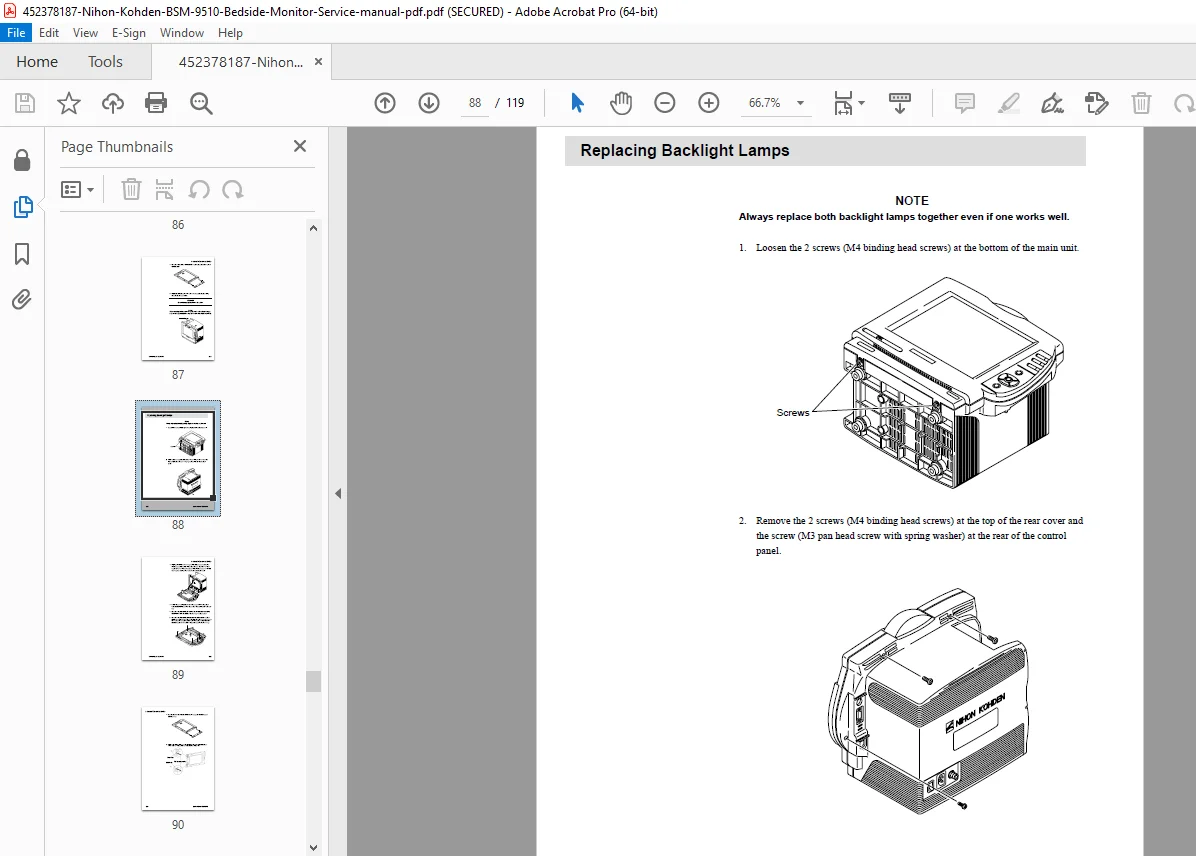
- Replacing Backlight Lamps
- Replacing LCD Filter
- Replacing OPERATION Board
- Replacing Lithium Battery
Section 6 — Maintenance
- Maintenance Check Items:
- External — physical inspection
- Safety — electrical safety checks
- Modules — module-level checks
- Display — visual inspection
- Measuring Parameters — functional verification
- Recorder — paper and print quality
- Backup — data backup verification
- Others — miscellaneous checks
Section 7 — Adjustment
Section 8 — Replaceable Parts List
- Main Unit Parts — with part numbers and descriptions
Section 9 — Connector Pin Assignments
- Alarm Output Socket (ALARM)
- General Serial Socket (SERIAL)
- Network Socket (NETWORK)
- JA Output Socket
- MAIN Board Connectors
- EXT JA Board Connectors
- Memory Card Connector
- OPERATION Connector
- LED Connector
- LCD Connector
- JA Motherboard Connector
- Power Supply Unit Connectors
- BDM Connector
- DEBUG Connector
🛡️ Safety & Compliance Standards
- IEC 60601-1 (1988, Amendment 1 & 2) — General safety
- IEC 60601-1-1 — Safety of medical electrical systems
- IEC 60601-1-2 — Electromagnetic compatibility
- IEC 60601-2-27 — ECG monitoring safety
- IEC 60601-2-30 — Automatic cycling NIBP safety
- IEC 60601-2-34 — Direct (invasive) blood pressure safety
- CE Mark — MDD 93/42/EEC compliant
- Protection Type: Class I Equipment; CF and BF applied parts; Defibrillation-proof on ECG, SpO2, NIBP, IBP, Temp inputs
💡 Why You Need This Manual
Critical care equipment downtime can be life-threatening. This Nihon Kohden BSM-9510 Life Scope M service manual gives you factory-level board descriptions, step-by-step disassembly procedures, full diagnostic check sequences, and a complete replaceable parts list — purchase now, download instantly, and restore your patient monitor to full operation today