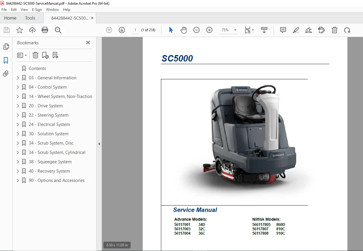
Nilfisk Advance SC5000 Floor Scrubber Service Manual 32C/36C/34D PDF
Original price was: $85.00.$19.95Current price is: $19.95.
Complete factory service manual for Nilfisk Advance SC5000 commercial floor scrubber machines including models 32C, 36C, and 34D (Nilfisk 810C, 910C, 860D). Professional technical documentation covering all major systems: control systems, drive motors, electrical circuits, solution delivery, scrub decks (disc and cylindrical), squeegee systems, and battery management. Includes detailed wiring diagrams, troubleshooting error codes, removal/installation procedures, and maintenance schedules.
Description
Nilfisk Advance SC5000 Floor Scrubber Service Manual 32C/36C/34D PDF DOWNLOAD
DESCRIPTION
This comprehensive Nilfisk Advance SC5000 Service Manual provides complete technical documentation for professional maintenance and repair of commercial ride-on floor scrubber machines. Designed for factory-trained service personnel and authorized service centers, this manual covers all SC5000 model variants sold under both the Advance and Nilfisk brand names.
Models Covered
Advance Models:
- SC5000 32C (32-inch cleaning path, cylindrical deck)
- SC5000 36C (36-inch cleaning path, cylindrical deck)
- SC5000 34D (34-inch cleaning path, disc deck)
Nilfisk Equivalent Models:
- SC5000 810C (corresponds to Advance 32C)
- SC5000 910C (corresponds to Advance 36C)
- SC5000 860D (corresponds to Advance 34D)
Part Numbers:
- Advance: 56117001, 56117003, 56117004
- Nilfisk: 566117805, 56117807, 56117808
Complete Manual Contents
CHAPTER 03: GENERAL INFORMATION
- Complete machine description and specifications
- Service manual purpose and application guidelines
- Reference manuals and information sources
- Revision history and documentation updates
- Parts and service contact information
- Diagnostic and service tools requirements
- Nameplate identification and serial number location
- Comprehensive Safety Instructions – Critical safety symbols and warnings
- General Safety Instructions – Operational safety procedures
- Transporting the Machine – Safe transport guidelines
- Moving a Disabled Machine – Emergency procedures
- Lifting the Machine – Proper lifting points and procedures
- Technical Specifications – Complete machine dimensions and capacities
- Fastener Torque Specifications – Proper tightening torques
- Maintenance Schedule – Preventive maintenance intervals
- Lubrication Points – Comprehensive lubrication guide
- Know Your Machine – Component identification and locations
- Main assemblies overview with detailed illustrations
- Machine components from front RH and rear LH views
CHAPTER 04: CONTROL SYSTEM Complete control system documentation including:
- Functional Description – System operation and logic
- Functional Diagram – System flow charts
- Drive Controller – Traction motor control system
- Power Module – Main power distribution and management
- Main Machine Controller – Central control unit operation
- Main controller operational modes
- Operational mode prerequisites
- Control Panel – User interface and display functions
- CAN Bus Communication – Controller area network protocols
- Component Locations – Physical placement diagrams
- Main Machine Controller Programming:
- Service mode access procedures
- Menu navigation instructions
- Programming menu complete outline
- Hours menu for service tracking
- Faults menu and error code viewing
- Keys menu for user authorization
- Authorizing and deauthorizing user keys
- Service menu with A1 Main Controller settings
- A3 Power Module programming
- A4 Drive Controller configuration
- Output test procedures
- Deck lift testing
- Panel test functions
- Options menu configuration
- Configuration menu settings
- System menu parameters
- Impact log for diagnostics
- Comprehensive Troubleshooting:
- Main Controller (A1) error codes with solutions
- Power Module (A2) error codes and diagnostics
- User Interface (A9) error codes
- Specifications – Electrical specifications and sample voltage measurements
- Maintenance – Firmware update procedures
- Removal and Installation – Main machine controller replacement
CHAPTER 14: WHEEL SYSTEM, NON-TRACTION
- Functional description of rear wheel assembly
- Removal and Installation:
- Rear wheel bearings and seal replacement
- Rear brake calipers service procedures
CHAPTER 20: DRIVE SYSTEM Complete traction system documentation:
- Functional Description – Drive system operation
- Drive Motor – Traction motor specifications
- Drive Pedal Potentiometer – Speed control sensor
- Drive Controller – Motor controller functions
- Operational mode prerequisites
- Troubleshooting:
- Drive Controller (A4) comprehensive error codes
- Systematic diagnostic procedures
- Removal and Installation:
- Drive controller replacement
- Drive wheel assembly service
- Electromechanical brake maintenance
- Drive tire replacement procedures
- Specifications – Drive system technical data
- Sample shop voltage measurements for diagnostics
CHAPTER 22: STEERING SYSTEM
- Functional description of steering mechanisms
- Maintenance and Adjustment:
- Steering chain tension adjustment procedures
- Removal and Installation:
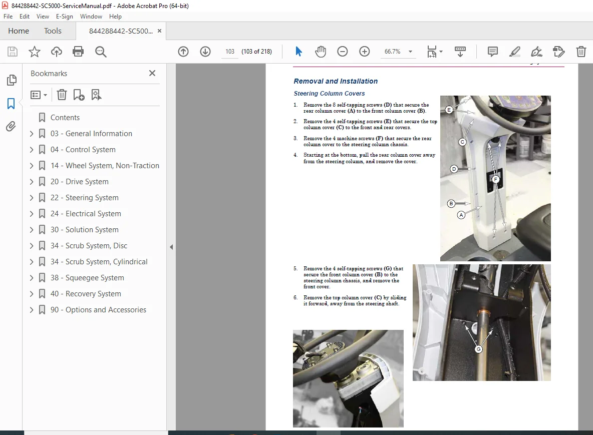
- Steering column covers
- Steering offset box service
CHAPTER 24: ELECTRICAL SYSTEM Comprehensive electrical system documentation:
- Functional Description – Complete electrical architecture
- Low Voltage Cutout – Battery protection system
- Onboard Battery Charger – Charging system operation
- Component Locations – Electrical component placement diagrams
- Troubleshooting:
- Battery testing procedures
- Battery charger error codes with diagnostics
- Maintenance and Adjustment:
- Battery settings and configuration
- Onboard battery charger maintenance
- Removal and Installation:
- Battery pack replacement procedures
- Complete Wiring Diagrams:
- Understanding electrical circuit diagram features
- Device labeling conventions
- Navigation instructions
- Electrical Circuit Diagram (8 sheets):
- Sheet 1: Contents and overview
- Sheet 2: Power/Charger/Main Controller Power
- Sheet 3: Controller Power distribution
- Sheet 4: Main Controller Functions
- Sheet 5: Power Module
- Sheet 6: Drive Module
- Sheet 7: Vehicle Circuits
- Sheet 8: CAN Bus network
- Condensed Electrical Circuit Diagram (3 sheets):
- Sheet 1: Main Machine Controller
- Sheet 2: Power Module
- Sheet 3: Drive Controller
- Using the Wiring Diagram – Troubleshooting guide
- Wire number system
- Splice point identification
- Connector number cross-reference
- Wiring Diagram (2 main sheets + appendices):
- Appendix A: CAN Wiring detailed diagrams
- Appendix B: KSI (Key Switch Ignition) Wiring
- Harness Diagram (7 sheets):
- Sheet 1: Navigation overview
- Sheet 2: Lower Electrical Bay, Front Chassis
- Sheet 3: Drive Controller, Traction Harness
- Sheet 4: Main Controller, KSI Relay Areas
- Sheet 5: Power Module, Machine Power
- Sheet 6: Lower Chassis and Scrub Deck Areas
- Sheet 7: Rear Chassis, Recovery, OBC, Column Harness
- 3D Harness Connector Diagrams:
- All harnesses overview
- Power distribution connections
- Main harness, electrical bay
- Column harness and main harness-front
- Traction harness connections
- Main harness, rear
- Electrical Connector Pin-Out Assignments – Complete connector details
CHAPTER 30: SOLUTION SYSTEM Complete solution delivery system:
- Functional Description – Water and detergent system operation
- Shutoff Valve – Solution flow control
- Solution Solenoid – Electric valve operation
- Solution Level Sensor – Tank level monitoring
- External Wash Options – Optional wash systems
- EcoFlex Option – Advanced dosing system
- Plumbing Diagram – Complete solution system schematic
- Operational mode prerequisites
- Troubleshooting:
- Detergent not flowing diagnostics
- Solution level indication problems
- Testing individual sensor bodies
- Removal and Installation:
- Solution solenoid replacement
- Detergent pump service
- Wash hose pump (optional) service
- Specifications – Solution system technical data
CHAPTER 34: SCRUB SYSTEM, DISC Disc scrub deck system documentation:
- Functional Description – Disc deck operation
- Deck Lift Actuator – Automatic deck height control
- Scrub Control – Brush pressure and speed control
- Operational mode prerequisites
- Circuit overview with schematics
- Maintenance and Adjustment:
- Lift actuator limit adjustment procedures
- Removal and Installation:
- Scrub deck removal and installation
- Deck lift actuator replacement
- Brush motor service
- Brush motor brush replacement
- Specifications – Disc deck technical data
- Special Tools:
- Actuator test kit usage
CHAPTER 34: SCRUB SYSTEM, CYLINDRICAL Cylindrical scrub deck system documentation:
- Functional Description – Cylindrical brush operation
- Deck Lift Actuator – Height control system
- Scrub Control – Brush management
- Operational mode prerequisites
- Circuit overview diagrams
- Maintenance and Adjustment:
- Lift actuator limit adjustment
- Removal and Installation:
- Scrub deck service procedures
- Deck lift actuator replacement
- Brush drive belt replacement
- Brush motor service
- Brush motor brush replacement
- Specifications – Cylindrical deck technical data
- Special Tools:
- Actuator test kit information
CHAPTER 38: SQUEEGEE SYSTEM Water recovery system documentation:
- Functional Description – Squeegee operation
- Squeegee Lift Actuator – Automatic lift mechanism
- Squeegee – Blade system and assembly
- Maintenance and Adjustment:
- Squeegee blade cleaning and inspection
- Squeegee height and tilt adjustment procedures
Key Features of This Service Manual
✓ Professional-Grade Documentation – Factory-authorized service information ✓ Dual Brand Coverage – Both Nilfisk and Advance model variants ✓ Multiple Deck Types – Both disc and cylindrical scrub systems ✓ Comprehensive Wiring Diagrams – 8-sheet electrical circuits plus 3D harness diagrams ✓ Complete Error Code Database – Controller error codes with solutions ✓ Detailed Illustrations – Component locations, exploded views, and assembly diagrams ✓ Step-by-Step Procedures – Removal, installation, and adjustment instructions ✓ Troubleshooting Guides – Systematic diagnostic procedures ✓ CAN Bus Communication – Advanced controller network diagnostics ✓ Service Programming – Controller configuration and settings menus ✓ Recent Edition – Updated 2023/2024 version with latest information
Technical Highlights
This SC5000 service manual emphasizes factory-trained technician procedures and requires specific diagnostic tools for proper service. The manual covers the advanced CAN bus communication system that links all controllers, providing comprehensive error code diagnostics through the main machine controller display. The programming sections include service mode access, controller firmware updates, and complete configuration menus for customizing machine performance.
Critical Service Requirements:
- Repairs should be performed by authorized Nilfisk/Advance service centers
- Factory-trained service personnel required for electronic systems
- Original Nilfisk/Advance replacement parts and accessories required
- Special diagnostic tools needed for controller programming
- Proper torque specifications must be followed for all fasteners
Who Should Use This Manual
- Authorized Nilfisk/Advance service centers
- Factory-trained floor scrubber technicians
- Commercial cleaning equipment repair specialists
- Facility maintenance teams with advanced technical training
- Industrial equipment service providers
- Technical training institutions teaching floor care equipment repair
File Details
- Manual Name: SC5000 Service Manual
- Form Number: 56043181 Rev C, 2023
- Models Covered: SC5000 32C, 36C, 34D (Advance) / 810C, 910C, 860D (Nilfisk)
- Manufacturer: Nilfisk Inc. / Nilfisk-Advance
- Document Type: Complete Factory Service Manual
- Edition: Revision C, 2023-2024
- Pages: 218 pages
- File Format: PDF (Digital Download)
- File Quality: Excellent – Professional technical publication with clear diagrams
- File Size: 19.0 MB