
NISSAN ENGINE REPAIR MANUAL
Original price was: $53.95.$21.95Current price is: $21.95.
NISSAN ENGINE REPAIR MANUAL – PDF DOWNLOAD
Description
NISSAN ENGINE REPAIR MANUAL – PDF DOWNLOAD
Customer Support: [email protected]
IMAGE PREVIEW:


DESCRIPTION:
NISSAN ENGINE REPAIR MANUAL – PDF DOWNLOAD
- NOTE: • Before removing and installing any control units, first turn the ignition switch to the LOCK position, then disconnect both battery cables. • After finishing work, confirm that all control unit connectors are connected properly, then re-connect both battery cables. •
- Always use CONSULT-III to perform self-diagnosis as a part of each function inspection after finishing work. If a DTC is detected, perform trouble diagnosis according to self-diagnosis results.
- For vehicle with steering lock unit, if the battery is disconnected or discharged, the steering wheel will lock and cannot be turned. If turning the steering wheel is required with the battery disconnected or discharged, follow the operation procedure below before starting the repair operation.
- OPERATION PROCEDURE 1. Connect both battery cables.
- NOTE: Supply power using jumper cables if battery is discharged. 2. Turn the ignition switch to ACC position. (At this time, the steering lock will be released.) 3.
- Disconnect both battery cables. The steering lock will remain released with both battery cables disconnected and the steering wheel can be turned. 4. Perform the necessary repair operation. 5.
- When the repair work is completed, re-connect both battery cables. With the brake pedal released, turn the ignition switch from ACC position to ON position, then to LOCK position.
- (The steering wheel will lock when the ignition switch is turned to LOCK position.) 6. Perform self-diagnosis check of all control units using CONSULT-III. Precaution for Supplemental Restraint System (SRS) “AIR BAG” and “SEAT BELT PRE-TENSIONER” INFOID:0000000006337223 The Supplemental Restraint System such as “AIR BAG” and “SEAT BELT PRE-TENSIONER”, used along with a front seat belt, helps to reduce the risk or severity of injury to the driver and front passenger for certain types of collision.
- This system includes seat belt switch inputs and dual stage front air bag modules. The SRS system uses the seat belt switches to determine the front air bag deployment, and may only deploy one front air bag, depending on the severity of a collision and whether the front occupants are belted or unbelted. Information necessary to service the system safely is included in the “SRS AIR BAG” and “SEAT BELT” of this Service Manual.
TABLE OF CONTENTS:
NISSAN ENGINE REPAIR MANUAL – PDF DOWNLOAD
PRECAUTION ………………………………………. 6
PRECAUTIONS ………………………………………….. 6
Precaution for Procedure without Cowl Top Cove.r. ….6
Precaution Necessary for Steering Wheel Rotation
after Battery Disconnect ………………………………6
Precaution for Supplemental Restraint System
(SRS) “AIR BAG” and “SEAT BELT PRE-TENSIONER”
…………………………………………………………6
Draining Engine Coolant ……………………………………7
Disconnecting Fuel Piping ………………………………….7
Precaution for Handling High Pressure Fuel System
…………………………………………………………………7
Removal and Disassembly …………………………………7
Inspection, Repair and Replacement …………………..7
Assembly and Installation ………………………………….7
Parts Requiring Angle Tightening ……………………….8
Liquid Gasket …………………………………………………..8
PREPARATION ……………………………………10
PREPARATION ………………………………………….10
Special Service Tools ………………………………………10
Commercial Service Tools ……………………………….11
BASIC INSPECTION …………………………….14
CAMSHAFT VALVE CLEARANCE ………………14
Inspection and Adjustment ……………………………….14
COMPRESSION PRESSURE ………………………17
Inspection ………………………………………………………17
SYMPTOM DIAGNOSIS ………………………..18
NOISE, VIBRATION AND HARSHNESS
(NVH) TROUBLESHOOTING ………………………18
NVH troubleshooting Chart ………………………………18
PERIODIC MAINTENANCE ……………………20
DRIVE BELT ……………………………………………..20
Exploded View ………………………………………………..20
Checking ………………………………………………………..20
Tension Adjustment …………………………………………20
Removal and Installation ………………………………….20
AIR CLEANER FILTER ……………………………….22
Removal and Installation ………………………………….22
SPARK PLUG ……………………………………………23
Exploded View ………………………………………………..23
Removal and Installation ………………………………….23
Inspection ………………………………………………………24
REMOVAL AND INSTALLATION …………..25
ENGINE COVER ………………………………………..25
Exploded View ………………………………………………..25
Removal and Installation ………………………………….25
AIR CLEANER AND AIR DUCT …………………..26
Exploded View ………………………………………………..26
Removal and Installation ………………………………….26
Inspection ………………………………………………………27
INTAKE MANIFOLD …………………………………..28
Exploded View ………………………………………………..28
Removal and Installation ………………………………….29
CHARGE AIR COOLER ………………………………31
Exploded View ………………………………………………..31
Removal and Installation ………………………………….31
Inspection ………………………………………………………32
CATALYST ………………………………………………..33
2WD …………………………………………………………………33
2WD : Exploded View ………………………………………33
2WD : Removal and Installation ………………………..33
4WD …………………………………………………………………34
4WD : Exploded View ………………………………………34
4WD : Removal and Installation ………………………..35
EM-2
TURBOCHARGER ……………………………………. 36
Exploded View ………………………………………………. 36
Removal and Installation ………………………………… 36
Inspection …………………………………………………….. 37
EXHAUST MANIFOLD ………………………………. 38
Exploded View ………………………………………………. 38
Removal and Installation ………………………………… 38
Inspection …………………………………………………….. 39
OIL PAN (LOWER) ……………………………………. 40
Exploded View ………………………………………………. 40
Removal and Installation ………………………………… 41
Inspection …………………………………………………….. 42
HIGH PRESSURE FUEL PUMP AND FUEL
HOSE ………………………………………………………. 43
Exploded View ………………………………………………. 43
Removal and Installation ………………………………… 43
Inspection …………………………………………………….. 46
FUEL INJECTOR AND FUEL TUBE ……………. 47
Exploded View ………………………………………………. 47
Removal and Installation ………………………………… 47
Inspection …………………………………………………….. 52
IGNITION COIL, SPARK PLUG AND ROCKER
COVER ……………………………………………….. 53
Exploded View ………………………………………………. 53
Removal and Installation ………………………………… 53
UNIT REMOVAL AND INSTALLATION …. 55
ENGINE ASSEMBLY …………………………………. 55
2WD ……………………………………………………………….. 55
2WD : Exploded View …………………………………….. 55
2WD : Removal and Installation ………………………. 55
2WD : Inspection …………………………………………… 58
4WD ……………………………………………………………….. 59
4WD : Exploded View …………………………………….. 59
4WD : Removal and Installation ………………………. 59
4WD : Inspection …………………………………………… 62
UNIT DISASSEMBLY AND ASSEMBLY … 63
ENGINE STAND SETTING …………………………. 63
Setting …………………………………………………………. 63
ENGINE UNIT …………………………………………… 65
Disassembly …………………………………………………. 65
Assembly ……………………………………………………… 65
DRIVE BELT AUTO TENSIONER AND IDLER
PULLEY …………………………………………………… 66
Exploded View ………………………………………………. 66
Removal and Installation ………………………………… 66
TIMING CHAIN …………………………………………. 67
Exploded View ………………………………………………. 67
Removal and Installation ………………………………… 68
Inspection ……………………………………………………… 76
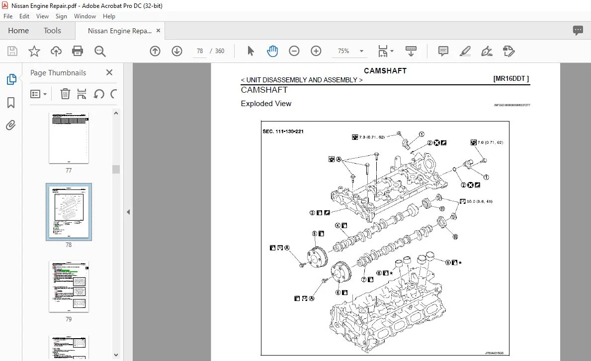
CAMSHAFT ……………………………………………… 78
Exploded View ………………………………………………. 78
Removal and Installation …………………………………. 79
Inspection ……………………………………………………… 82
OIL SEAL …………………………………………………. 87
VALVE OIL SEAL ……………………………………………. 87
VALVE OIL SEAL : Removal and Installation …….. 87
FRONT OIL SEAL ……………………………………………. 87
FRONT OIL SEAL : Removal and Installation ……. 88
REAR OIL SEAL ……………………………………………… 88
REAR OIL SEAL : Removal and Installation ………. 88
CYLINDER HEAD ……………………………………… 90
Exploded View ………………………………………………. 90
Removal and Installation …………………………………. 91
Disassembly and Assembly …………………………….. 92
Inspection ……………………………………………………… 96
OIL PAN (UPPER) …………………………………….. 99
Exploded View ………………………………………………. 99
Removal and Installation ……………………………….. 100
Inspection ……………………………………………………. 102
CYLINDER BLOCK …………………………………..103
Exploded View …………………………………………….. 103
Disassembly and Assembly …………………………… 104
Inspection ……………………………………………………. 112
HOW TO SELECT PISTON AND BEARING ..122
Description ………………………………………………….. 122
Piston …………………………………………………………. 122
Connecting Rod Bearing ……………………………… 123
Main Bearing ………………………………………………. 125
SERVICE DATA AND SPECIFICATIONS
(SDS) …………………………………………………129
SERVICE DATA AND SPECIFICATIONS
(SDS) ………………………………………………………129
General Specification ……………………………………. 129
Drive Belt ……………………………………………………. 129
Spark Plug ………………………………………………….. 129
Exhaust Manifold …………………………………………. 130
Camshaft …………………………………………………….. 130
Cylinder Head ……………………………………………… 132
Cylinder Block ……………………………………………… 134
Connecting Rod Bearing ……………………………….. 138
Main Bearing ……………………………………………….. 138
HR16DE
PRECAUTION …………………………………….140
PRECAUTIONS ………………………………………..140
Precaution for Procedure without Cowl Top Cover . 140
Precaution Necessary for Steering Wheel Rotation
after Battery Disconnect ………………………….. 140
EM-3
Precaution for Supplemental Restraint System
(SRS) “AIR BAG” and “SEAT BELT PRE-TENSIONER”
…………………………………………………….. 140
Draining Engine Coolant ……………………………….. 141
Disconnecting Fuel Piping ……………………………… 141
Removal and Disassembly …………………………….. 141
Inspection, Repair and Replacement ………………. 141
Assembly and Installation ……………………………… 141
Parts Requiring Angle Tightening …………………… 142
Liquid Gasket ………………………………………………. 142
PREPARATION …………………………………. 144
PREPARATION ……………………………………….. 144
Special Service Tools ……………………………………. 144
Commercial Service Tools …………………………….. 145
BASIC INSPECTION ………………………….. 148
CAMSHAFT VALVE CLEARANCE ……………. 148
Inspection and Adjustment …………………………….. 148
COMPRESSION PRESSURE ……………………. 151
Inspection ……………………………………………………. 151
SYMPTOM DIAGNOSIS ……………………… 152
NOISE, VIBRATION AND HARSHNESS
(NVH) TROUBLESHOOTING ……………………. 152
NVH troubleshooting Chart ……………………………. 152
PERIODIC MAINTENANCE …………………. 154
DRIVE BELT ……………………………………………. 154
Checking …………………………………………………….. 154
Tension Adjustment ……………………………………… 154
Removal and Installation ……………………………….. 155
AIR CLEANER FILTER …………………………….. 157
Exploded View …………………………………………….. 157
Removal and Installation ……………………………….. 157
SPARK PLUG …………………………………………. 159
Removal and Installation ……………………………….. 159
Inspection ……………………………………………………. 159
REMOVAL AND INSTALLATION ………… 160
DRIVE BELT IDLER PULLEY ……………………. 160
Removal and Installation ……………………………….. 160
AIR CLEANER AND AIR DUCT ………………… 161
Exploded View …………………………………………….. 161
Removal and Installation ……………………………….. 161
Inspection ……………………………………………………. 162
INTAKE MANIFOLD …………………………………. 163
Exploded View …………………………………………….. 163
Removal and Installation ……………………………….. 163
EXHAUST MANIFOLD ……………………………… 166
Exploded View …………………………………………….. 166
Removal and Installation ………………………………..166
Inspection …………………………………………………….167
OIL PAN (LOWER) ………………………………….. 169
Exploded View ………………………………………………169
Removal and Installation ………………………………..170
Inspection …………………………………………………….172
FUEL INJECTOR AND FUEL TUBE ………….. 173
Exploded View ………………………………………………173
Removal and Installation ………………………………..173
Inspection …………………………………………………….177
IGNITION COIL, SPARK PLUG AND ROCKER
COVER ……………………………………………… 178
Exploded View ………………………………………………178
Removal and Installation ………………………………..178
TIMING CHAIN ………………………………………… 181
Exploded View ………………………………………………181
Removal and Installation ………………………………..182
Inspection …………………………………………………….189
CAMSHAFT …………………………………………….. 191
Exploded View ………………………………………………191
Removal and Installation ………………………………..191
Inspection …………………………………………………….200
OIL SEAL ……………………………………………….. 205
VALVE OIL SEAL ……………………………………………205
VALVE OIL SEAL : Removal and Installation …….205
FRONT OIL SEAL ……………………………………………205
FRONT OIL SEAL : Removal and Installation ……206
REAR OIL SEAL ……………………………………………..206
REAR OIL SEAL : Removal and Installation ……..206
CYLINDER HEAD ……………………………………. 208
Exploded View ………………………………………………208
Removal and Installation ………………………………..209
Disassembly and Assembly …………………………….211
Inspection …………………………………………………….212
UNIT REMOVAL AND INSTALLATION … 215
ENGINE ASSEMBLY ……………………………….. 215
Exploded View ………………………………………………215
Removal and Installation ………………………………..215
Inspection …………………………………………………….218
UNIT DISASSEMBLY AND ASSEMBLY . 219
ENGINE STAND SETTING ……………………….. 219
Setting …………………………………………………………219
ENGINE UNIT ………………………………………….. 221
Disassembly …………………………………………………221
Assembly ……………………………………………………..221
OIL PAN (UPPER) …………………………………… 222
Exploded View ………………………………………………222
EM-4
Removal and Installation ………………………………..223
Inspection …………………………………………………….226
CYLINDER BLOCK …………………………………. 227
Exploded View ………………………………………………227
Disassembly and Assembly …………………………….228
Inspection …………………………………………………….236
HOW TO SELECT PISTON AND BEARING .. 246
Description ……………………………………………………246
Connecting Rod Bearing ………………………………..246
Main Bearing ………………………………………………..248
SERVICE DATA AND SPECIFICATIONS
(SDS) …………………………………………………250
SERVICE DATA AND SPECIFICATIONS
(SDS) ……………………………………………………… 250
General Specification …………………………………….250
Drive Belt ……………………………………………………..250
Spark Plug ……………………………………………………251
Exhaust Manifold …………………………………………..251
Camshaft ……………………………………………………..251
Cylinder head ……………………………………………….253
Cylinder Block ……………………………………………….255
Main Bearing ………………………………………………..257
Connecting Rod Bearing ………………………………..258
K9K
PRECAUTION …………………………………….260
PRECAUTIONS ………………………………………. 260
Precaution for Procedure without Cowl Top Cover. .260
Precaution Necessary for Steering Wheel Rotation
after Battery Disconnect …………………………..260
Precaution for Supplemental Restraint System
(SRS) “AIR BAG” and “SEAT BELT PRE-TENSIONER”
………………………………………………………260
Draining Engine Coolant …………………………………261
Disconnecting Fuel Piping ………………………………261
Removal and Disassembly ……………………………..261
Inspection, Repair and Replacement ……………….261
Assembly and Installation ……………………………….261
Parts Requiring Angle Tightening …………………….262
Liquid Gasket ………………………………………………..262
Precaution for Diesel Equipment ……………………..263
Parts To Be Replaced After Removal ……………….266
Installation of Thread Inserts …………………………..266
PREPARATION …………………………………..267
PREPARATION ………………………………………. 267
Special Service Tool ………………………………………267
Commercial Service Tool ……………………………….269
BASIC INSPECTION ……………………………272
CAMSHAFT VALVE CLEARANCE ……………. 272
Valve Clearance ……………………………………………272
SYMPTOM DIAGNOSIS ………………………274
NOISE, VIBRATION AND HARSHNESS
(NVH) TROUBLESHOOTING ……………………..274
NVH Troubleshooting – Engine Noise ……………… 274
Use the Chart Below to Help You Find the Cause
of the Symptom ……………………………………………. 275
PERIODIC MAINTENANCE ………………….276
DRIVE BELT …………………………………………….276
Checking Drive Belts …………………………………….. 276
Tension Adjustment ……………………………………… 276
Removal and Installation ……………………………….. 276
AIR CLEANER FILTER ……………………………..278
Exploded View …………………………………………….. 278
Removal and Installation ……………………………….. 278
REMOVAL AND INSTALLATION ………….280
AIR CLEANER AND AIR DUCT ………………….280
Exploded View …………………………………………….. 280
Removal and Installation ……………………………….. 280
CHARGE AIR COOLER …………………………….281
Exploded View …………………………………………….. 281
Removal and Installation ……………………………….. 281
Inspection ……………………………………………………. 282
EGR VALVE …………………………………………….283
Exploded View …………………………………………….. 283
Removal and Installation ……………………………….. 283
TURBOCHARGER ……………………………………284
Exploded View …………………………………………….. 284
Removal and Installation ……………………………….. 284
Inspection ……………………………………………………. 285
EXHAUST MANIFOLD ………………………………286
Exploded View …………………………………………….. 286
Removal and Installation ……………………………….. 286
Inspection ……………………………………………………. 287
OIL PAN …………………………………………………..288
Exploded View …………………………………………….. 288
Removal and Installation ……………………………….. 288
Inspection ……………………………………………………. 291
GLOW PLUG ……………………………………………292
Exploded View …………………………………………….. 292
Removal and Installation ……………………………….. 292
VACUUM PUMP ……………………………………….293
Exploded View …………………………………………….. 293
Removal and Installation ……………………………….. 293
Inspection ……………………………………………………. 293
INJECTION TUBE AND FUEL INJECTOR …..294
Exploded View …………………………………………….. 294
Removal and Installation ……………………………….. 294
5TH INJECTOR ………………………………………..296
Exploded View …………………………………………….. 296
EM-5
C
D
E
F
G
H
I
J
K
L
M
EM
A
N
O
P
Removal and Installation ……………………………….. 296
HIGH PRESSURE SUPPLY PUMP ……………. 298
Exploded View …………………………………………….. 298
Removal and Installation ……………………………….. 298
ROCKER COVER …………………………………….. 300
Exploded View …………………………………………….. 300
Removal and Installation ……………………………….. 300
TIMING BELT ………………………………………….. 302
Exploded View …………………………………………….. 302
Removal and Installation ……………………………….. 302
CYLINDER HEAD ……………………………………. 311
Exploded View …………………………………………….. 311
Removal and Installation ……………………………….. 311
Cleaning ……………………………………………………… 321
Inspection ……………………………………………………. 321
UNIT REMOVAL AND INSTALLATION … 326
ENGINE ASSEMBLY ……………………………….. 326
Exploded View ………………………………………………326
Removal and Installation ………………………………..326
Inspection …………………………………………………….328
UNIT DISASSEMBLY AND ASSEMBLY . 329
ENGINE STAND SETTING ……………………….. 329
Preparing the engine to be on the stand …………..329
CYLINDER BLOCK ………………………………….. 330
Disassembly and Assembly …………………………….330
Inspection …………………………………………………….353
SERVICE DATA AND SPECIFICATIONS
(SDS) ………………………………………………… 359
SERVICE DATA AND SPECIFICATIONS
(SDS) ……………………………………………………… 359
General Specification …………………………………….359
Tightening torque …………………………………………..359
PLEASE NOTE:
- This is the same manual used by the DEALERSHIPS to SERVICE your vehicle.
- The manual can be all yours – Once payment is complete, you will be taken to the download page from where you can download the manual. All in 2-5 minutes time!!
- Need any other service / repair / parts manual, please feel free to contact us at heydownloadss @gmail.com . We may surprise you with a nice offer