Nissan Frontier Engine Control System Service Manual PDF
Original price was: $120.00.$29.95Current price is: $29.95.
Download the official Nissan Frontier engine control system service manual PDF for 2000 models with KA, NA, and Z24S engines. This Nissan Frontier repair guide for engine control download covers DTC codes, troubleshooting, wiring diagrams, sensor inspections, and emission systems. Perfect for DIY mechanics needing a Nissan D21 D22 ECM service handbook or Frontier fuel injection maintenance manual. High-quality 338-page PDF with step-by-step procedures and vacuum hose drawings.
Description
Nissan Frontier Engine Control System Service Manual PDF DOWNLOAD
Description
The Nissan Frontier engine control system service manual PDF is a detailed technical guide for diagnosing, repairing, and maintaining the engine management systems in 2000 Nissan Frontier trucks. Covering KA (KA24DE multiport injection), NA (carbureted models), and Z24S (carbureted) engines, it includes on-board diagnostics, trouble code explanations, fail-safe modes, symptom charts, component locations, wiring diagrams, and inspection procedures for sensors, fuel systems, ignition, and emission controls. Essential for addressing issues like overheat, sensor failures, and fuel pump problems.
File Details:
- Manual Name: Engine Control System Service Manual Nissan Frontier
- Models Covered: Nissan Frontier (D21/D22 series) with KA, NA, Z24S engines
- Year: 2000
- Manual PDF Quality: High-resolution, searchable text with diagrams, charts, and schematics
- No. of Pages: 338
The manual features a comprehensive table of contents, extracted and categorized below using bullet points for main sections and sub-bullets for subsections. It provides structured guidance for both electronic fuel injection and carbureted systems across engine variants.
Table of Contents:
- Diagnostic Trouble Code Index (Page 2)
- Alphabetical & Numerical Index for DTC (KA engine)
- Precautions and Preparation (Pages 3-5)
- Special Service Tools
- Commercial Service Tool
- Supplemental Restraint System (SRS) “AIR BAG” (4WD models)
- Supplemental Restraint System (SRS) “AIR BAG” (2WD models)
- KA Engine Section (Pages 6-172)
- Precautions and Preparation
- Engine Fuel & Emission Control System
- Precautions
- Engine and Emission Control Overall System
- Circuit Diagram
- System Diagram
- ECCS Component Parts Location
- Vacuum Hose Drawing
- System Chart
- Engine and Emission Basic Control System Description
- Multiport Fuel Injection (MFI) System
- Distributor Ignition (DI) System
- Air Conditioning Cut Control
- Fuel Cut Control (at no load & high engine speed)
- Evaporative Emission System
- Description
- Inspection
- Positive Crankcase Ventilation
- Description
- Inspection
- Basic Service Procedure
- Fuel Pressure Release
- Fuel Pressure Check
- Injector Removal and Installation
- Fast Idle Cam (FIC) Inspection and Adjustment
- Idle Speed/Ignition Timing/Idle Mixture Ratio Adjustment
- On Board Diagnostic System Description
- Introduction
- Diagnostic Trouble Code (DTC)
- Malfunction Indicator Lamp (MIL)
- CONSULT
- Trouble Diagnosis – Introduction
- Introduction
- Diagnostic Worksheet
- Trouble Diagnosis – Work Flow
- Work Flow
- Description for Work Flow
- Trouble Diagnosis – Basic Inspection
- Basic Inspection
- Trouble Diagnosis – General Description
- Fail-Safe Chart
- Symptom Matrix Chart
- CONSULT Reference Value in Data Monitor Mode
- Major Sensor Reference Graph in Data Monitor Mode
- ECM Terminals and Reference Value
- Trouble Diagnosis for Power Supply
- Main Power Supply and Ground Circuit
- Trouble Diagnosis for “CAMSHAFT POSI SEN” (DTC 11)
- Camshaft Position Sensor (CMPS)
- Trouble Diagnosis for “MASS AIR FLOW SEN” (DTC 12)
- Mass Air Flow Sensor (MAFS)
- Trouble Diagnosis for “COOLANT TEMP SEN” (DTC 13)
- Engine Coolant Temperature Sensor (ECTS)
- Trouble Diagnosis for “IGN SIGNAL-PRIMARY” (DTC 21)
- Ignition Signal
- Trouble Diagnosis for “OVER HEAT” (DTC 28)
- Overheat
- Trouble Diagnosis for “INT AIR TEMP SEN” (DTC 41)
- Intake Air Temperature Sensor
- Trouble Diagnosis for “THROTTLE POSI SEN” (DTC 43)
- Throttle Position Sensor
- Trouble Diagnosis for Non-Detectable Items
- Vehicle Speed Sensor (VSS)
- Heated Oxygen Sensor (HO2S) – LHD Models
- Heated Oxygen Sensor Heater – LHD Models
- Idle Air Control Valve (IACV) – Auxiliary Air Control (AAC) Valve
- Neutral Position Switch
- EVAP Canister Purge Control Solenoid Valve
- Injector
- Start Signal
- Fuel Pump
- Power Steering Oil Pressure Switch
- Swirl Control Valve Control Solenoid Valve
- IACV-FICD Solenoid Valve
- MIL & Data Link Connectors
- Precautions and Preparation
- NA Engine Section (Pages 173-217)
- Engine and Emission Control Overall System
- Component Parts Location
- System Diagram
- Circuit Diagram
- Vacuum Hose Drawing
- Carburetor
- Construction
- Major Service Operation
- Disassembling Carburetor Harness Connector
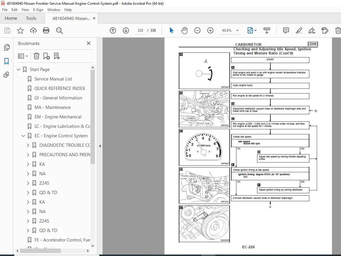
- Checking and Adjusting Idle Speed, Ignition Timing and Mixture Ratio
- Checking and Adjusting Idle-rpm, Ignition Timing and Mixture Ratio
- Fuel Level
- Automatic Choke
- Fast Idle
- Vacuum Break
- Accelerator Pump
- IACV-idle up Control
- Fuel Cut Control System
- Mixture By-pass Control System
- ISC-FI Pot
- Mechanical Fuel Pump (Models without Power Steering)
- Fuel Pump
- Operation
- Fuel Pressure
- Electric Fuel Pump Control System (Models with Power Steering)
- Description
- Operation
- Wiring Diagram – FPCM –
- Inspection
- Fuel Return Control System
- Wiring Diagram – F/RTN –
- Description
- Operation
- Inspection
- Ignition Control System
- Wiring Diagram – IGN –
- System Description
- Component Parts Description
- Component Parts Inspection
- Ignition Control System – Distributor
- Disassembly
- Distributor Component Check
- Exhaust Emission Control System
- Boost Control Valve (BCV)
- Idle Compensator
- Idle Compensator
- Inspection
- Evaporative Emission Control System
- Description
- Inspection
- Crankcase Emission Control System
- Description
- Inspection
- Engine and Emission Control Overall System
- Z24S Engine Section (Pages 218+)
- Engine and Emission Control Overall System
- Component Parts Location
- System Diagram
- Circuit Diagram
- Vacuum Hose Drawing
- Carburetor
- Construction
- Major Service Operation
- Disassembling Carburetor Harness Connector
- Checking and Adjusting Idle Speed, Ignition Timing and Mixture Ratio
- Fuel Level
- Automatic Choke
- Fast Idle
- Vacuum Break
- Accelerator Pump
- Fuel Cut Control System
- ISC-FI Pot
- Electric Fuel Pump
- Description
- Operation
- Wiring Diagram – FPCM –
- Engine and Emission Control Overall System
This Nissan D21 D22 ECM service handbook equips you with factory-level insights for efficient repairs as a Nissan Frontier repair guide for engine control download.
Tackle engine issues like a pro—download this Nissan Frontier engine control system service manual PDF now for instant access and save on shop visits!