Nissan MR16DDT HR16DE K9K Engine Repair Manual – PDF DOWNLOAD
Original price was: $78.95.$28.95Current price is: $28.95.
Nissan MR16DDT HR16DE K9K Engine Repair Manual – PDF DOWNLOAD
Description
Nissan MR16DDT HR16DE K9K Engine Repair Manual – PDF DOWNLOAD
FILE DETAILS:
Nissan MR16DDT HR16DE K9K Engine Repair Manual – PDF DOWNLOAD
Language : English
Pages : 360
Downloadable : Yes
File Type : PDF
Size: 3.31 MB
IMAGES PREVIEW OF THE MANUAL:
DESCRIPTION:
Nissan MR16DDT HR16DE K9K Engine Repair Manual – PDF DOWNLOAD
PRECAUTION:
Precaution for Procedure without Cowl Top Cover
When performing the procedure after removing cowl top cover, cover
the lower end of windshield with urethane, etc.
Precaution Necessary for Steering Wheel Rotation after Battery Disconnect
OPERATION PROCEDURE
1. Connect both battery cables.
NOTE:
Supply power using jumper cables if battery is discharged.
2. Turn the ignition switch to ACC position.
(At this time, the steering lock will be released.)
3. Disconnect both battery cables. The steering lock will remain released with both battery cables disconnected
and the steering wheel can be turned.
4. Perform the necessary repair operation.
5. When the repair work is completed, re-connect both battery cables. With the brake pedal released, turn
the ignition switch from ACC position to ON position, then to LOCK position. (The steering wheel will lock
when the ignition switch is turned to LOCK position.)
6. Perform self-diagnosis check of all control units using CONSULT-III.
TABLE OF CONTENTS:
Nissan MR16DDT HR16DE K9K Engine Repair Manual – PDF DOWNLOAD
QUICK REFERENCE INDEX 0
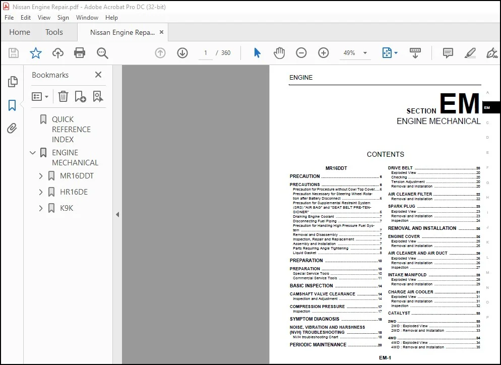
ENGINE MECHANICAL 1
MR16DDT 6
PRECAUTION 6
PRECAUTIONS 6
Precaution for Procedure without Cowl Top Cover 6
Precaution Necessary for Steering Wheel Rotation after Battery Disconnect 6
OPERATION PROCEDURE 6
Precaution for Supplemental Restraint System (SRS) “AIR BAG” and “SEAT BELT PRE-TENSIONER” 6
PRECAUTIONS WHEN USING POWER TOOLS (AIR OR ELECTRIC) AND HAMMERS 7
Draining Engine Coolant 7
Disconnecting Fuel Piping 7
Precaution for Handling High Pressure Fuel System 7
Removal and Disassembly 7
Inspection, Repair and Replacement 7
Assembly and Installation 7
Parts Requiring Angle Tightening 8
Liquid Gasket 8
REMOVAL OF LIQUID GASKET SEALING 8
LIQUID GASKET APPLICATION PROCEDURE 8
PREPARATION 10
PREPARATION 10
Special Service Tools 10
Commercial Service Tools 11
BASIC INSPECTION 14
CAMSHAFT VALVE CLEARANCE 14
Inspection and Adjustment 14
INSPECTION 14
ADJUSTMENT 15
COMPRESSION PRESSURE 17
Inspection 17
SYMPTOM DIAGNOSIS 18
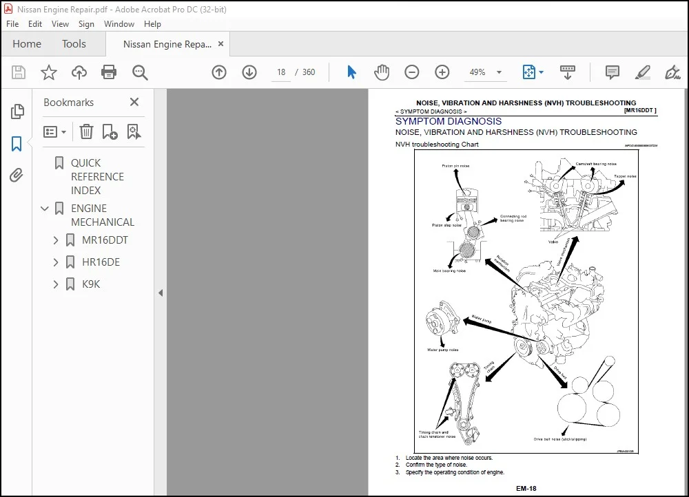
NOISE, VIBRATION AND HARSHNESS (NVH) TROUBLESHOOTING 18
NVH troubleshooting Chart 18
PERIODIC MAINTENANCE 20
DRIVE BELT 20
Exploded View 20
Checking 20
Tension Adjustment 20
Removal and Installation 20
REMOVAL 20
INSTALLATION 21
AIR CLEANER FILTER 22
Removal and Installation 22
REMOVAL 22
INSTALLATION 22
SPARK PLUG 23
Exploded View 23
Removal and Installation 23
REMOVAL 23
INSTALLATION 24
Inspection 24
INSPECTION AFTER REMOVAL 24
REMOVAL AND INSTALLATION 25
ENGINE COVER 25
Exploded View 25
Removal and Installation 25
REMOVAL 25
INSTALLATION 25
AIR CLEANER AND AIR DUCT 26
Exploded View 26
Removal and Installation 26
REMOVAL 26
INSTALLATION 27
Inspection 27
INSPECTION AFTER REMOVAL 27
INTAKE MANIFOLD 28
Exploded View 28
Removal and Installation 29
REMOVAL 29
INSTALLATION 29
Intake Manifold 29
Electric Throttle Control Actuator 30
CHARGE AIR COOLER 31
Exploded View 31
Removal and Installation 31
REMOVAL 31
INSTALLATION 32
Inspection 32
INSPECTION AFTER REMOVAL 32
CATALYST 33
2WD 33
2WD : Exploded View 33
2WD : Removal and Installation 33
REMOVAL 33
INSTALLATION 34
4WD 34
4WD : Exploded View 34
4WD : Removal and Installation 35
REMOVAL 35
INSTALLATION 35
TURBOCHARGER 36
Exploded View 36
Removal and Installation 36
REMOVAL 36
INSTALLATION 37
Inspection 37
INSPECTION AFTER REMOVAL 37
INSPECTION AFTER INSTALLATION 37
EXHAUST MANIFOLD 38
Exploded View 38
Removal and Installation 38
REMOVAL 38
INSTALLATION 39
Inspection 39
INSPECTION AFTER REMOVAL 39
Surface Distortion 39
OIL PAN (LOWER) 40
Exploded View 40
Removal and Installation 41
REMOVAL 41
INSTALLATION 41
Inspection 42
INSPECTION AFTER REMOVAL 42
INSPECTION AFTER INSTALLATION 42
HIGH PRESSURE FUEL PUMP AND FUEL HOSE 43
Exploded View 43
Removal and Installation 43
REMOVAL 43
INSTALLATION 44
Inspection 46
INSPECTION AFTER INSTALLATION 46
Check for Fuel Leakage 46
FUEL INJECTOR AND FUEL TUBE 47
Exploded View 47
Removal and Installation 47
REMOVAL 48
INSTALLATION 50
Inspection 52
INSPECTION AFTER INSTALLATION 52
Check on Fuel Leakage 52
IGNITION COIL, SPARK PLUG AND ROCKER COVER 53
Exploded View 53
Removal and Installation 53
REMOVAL 53
INSTALLATION 54
UNIT REMOVAL AND INSTALLATION 55
ENGINE ASSEMBLY 55
2WD 55
2WD : Exploded View 55
2WD : Removal and Installation 55
REMOVAL 56
Outline 56
Preparation 56
Engine Room LH 56
Engine Room RH 56
Vehicle Underbody 56
Removal 57
Separation 57
INSTALLATION 58
Rear torque rod bracket 58
2WD : Inspection 58
INSPECTION AFTER INSTALLATION 58
Inspection for Leakage 58
4WD 59
4WD : Exploded View 59
4WD : Removal and Installation 59
REMOVAL 60
Outline 60
Preparation 60
Engine Room LH 60
Engine Room RH 60
Vehicle Underbody 60
Removal 61
Separation 61
INSTALLATION 62
4WD : Inspection 62
INSPECTION AFTER INSTALLATION 62
Inspection for Leakage 62
UNIT DISASSEMBLY AND ASSEMBLY 63
ENGINE STAND SETTING 63
Setting 63
ENGINE UNIT 65
Disassembly 65
Assembly 65
DRIVE BELT AUTO TENSIONER AND IDLER PULLEY 66
Exploded View 66
Removal and Installation 66
Removal 66
Installation 66
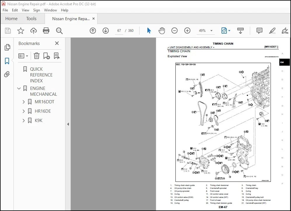
TIMING CHAIN 67
Exploded View 67
Removal and Installation 68
REMOVAL 68
INSTALLATION 72
Inspection 76
INSPECTION AFTER REMOVAL 76
Timing Chain 76
INSPECTION AFTER INSTALLATION 76
Inspection for Leakage 76
CAMSHAFT 78
Exploded View 78
Removal and Installation 79
REMOVAL 79
INSTALLATION 80
Inspection 82
INSPECTION AFTER REMOVAL 82
Camshaft Runout 82
Camshaft Cam Height 82
Camshaft Journal Oil Clearance 83
Camshaft End Play 83
Camshaft Sprocket Runout 84
Valve Lifter 84
Valve Lifter Clearance 84
INSPECTION AFTER INSTALLATION 85
Inspection of Camshaft Sprocket (INT) Oil Groove 85
OIL SEAL 87
VALVE OIL SEAL 87
VALVE OIL SEAL : Removal and Installation 87
REMOVAL 87
INSTALLATION 87
FRONT OIL SEAL 87
FRONT OIL SEAL : Removal and Installation 88
REMOVAL 88
INSTALLATION 88
REAR OIL SEAL 88
REAR OIL SEAL : Removal and Installation 88
REMOVAL 88
INSTALLATION 88
CYLINDER HEAD 90
Exploded View 90
REMOVAL 90
DISASSEMBLY 90
Removal and Installation 91
REMOVAL 91
INSTALLATION 92
Disassembly and Assembly 92
DISASSEMBLY 92
ASSEMBLY 94
Inspection 96
INSPECTION AFTER REMOVAL 96
Cylinder Head Bolts Outer Diameter 96
Cylinder Head Distortion 96
INSPECTION AFTER DISASSEMBLY 97
VALVE DIMENSIONS 97
VALVE GUIDE CLEARANCE 97
VALVE SEAT CONTACT 97
VALVE SPRING SQUARENESS 97
VALVE SPRING DIMENSIONS AND VALVE SPRING PRESSURE LOAD 98
INSPECTION AFTER INSTALLATION 98
Inspection for Leakage 98
OIL PAN (UPPER) 99
Exploded View 99
Removal and Installation 100
REMOVAL 100
INSTALLATION 100
Inspection 102
INSPECTION AFTER REMOVAL 102
CYLINDER BLOCK 103
Exploded View 103
Disassembly and Assembly 104
DISASSEMBLY 104
ASSEMBLY 106
Inspection 112
CRANKSHAFT END PLAY 112
CONNECTING ROD SIDE CLEARANCE 112
PISTON TO PISTON PIN OIL CLEARANCE 112
Piston Pin Hole Diameter 112
Piston Pin Outer Diameter 112
Piston to Piston Pin Oil Clearance 113
PISTON RING SIDE CLEARANCE 113
PISTON RING END GAP 113
CONNECTING ROD BEND AND TORSION 113
CONNECTING ROD BIG END DIAMETER 114
CONNECTING ROD BUSHING OIL CLEARANCE 114
Connecting Rod Bushing Inner Diameter 114
Piston Pin Outer Diameter 114
Connecting Rod Bushing Oil Clearance 115
CYLINDER BLOCK TOP SURFACE DISTORTION 115
MAIN BEARING HOUSING INNER DIAMETER 115
PISTON TO CYLINDER BORE CLEARANCE 115
Cylinder Bore Inner Diameter 116
Piston Skirt Diameter 116
Piston to Cylinder Bore Clearance 116
CRANKSHAFT MAIN JOURNAL DIAMETER 117
CRANKSHAFT PIN JOURNAL DIAMETER 117
OUT-OF-ROUND AND TAPER OF CRANKSHAFT 117
CRANKSHAFT RUNOUT 117
CONNECTING ROD BEARING OIL CLEARANCE 117
Method by Calculation 117
Method of Using Plastigage 118
MAIN BEARING OIL CLEARANCE 118
Method by Calculation 118
Method of Using Plastigage 118
MAIN BEARING CRUSH HEIGHT 119
CONNECTING ROD BEARING CRUSH HEIGHT 119
MAIN BEARING CAP BOLT OUTER DIAMETER 119
CONNECTING ROD CAP BOLT OUTER DIAMETER 119
CLOGGED OR DAMAGED OIL FILTER (FOR INTAKE VALVE TIMING CONTROL) 120
FLYWHEEL DEFLECTION (M/T MODELS) 120
MOVEMENT AMOUNT OF FLYWHEEL (M/T MODELS) 120
Movement Amount of Thrust (Fore-and-Aft) Direction 120
Movement Amount in Radial (Rotation) Direction 120
DRIVE PLATE (CVT MODELS) 121
HOW TO SELECT PISTON AND BEARING 122
Description 122
Piston 122
WHEN NEW CYLINDER BLOCK IS USED 122
WHEN CYLINDER BLOCK IS REUSED 122
PISTON SELECTION TABLE 123
Connecting Rod Bearing 123
WHEN NEW CONNECTING ROD AND CRANKSHAFT ARE USED 123
WHEN CONNECTING ROD AND CRANKSHAFT ARE REUSED 123
CONNECTING ROD BEARING SELECTION TABLE 124
CONNECTING ROD BEARING GRADE TABLE 124
UNDERSIZE BEARINGS USAGE GUIDE 124
Main Bearing 125
WHEN NEW CYLINDER BLOCK AND CRANKSHAFT ARE USED 125
WHEN CYLINDER BLOCK AND CRANKSHAFT ARE REUSED 126
MAIN BEARING SELECTION TABLE (No 1, 4, AND 5 JOURNAL) 126
MAIN BEARING SELECTION TABLE (No 2 AND 3 JOURNAL) 127
MAIN BEARING GRADE TABLE (ALL JOURNALS) 127
UNDERSIZE BEARING USAGE GUIDE 127
SERVICE DATA AND SPECIFICATIONS (SDS) 129
SERVICE DATA AND SPECIFICATIONS (SDS) 129
General Specification 129
GENERAL SPECIFICATIONS 129
Drive Belt 129
DRIVE BELT 129
Spark Plug 129
SPARK PLUG 129
Exhaust Manifold 130
EXHAUST MANIFOLD 130
Camshaft 130
CAMSHAFT 130
VALVE LIFTER 130
VALVE CLEARANCE 130
AVAILABLE VALVE LIFTER 131
Cylinder Head 132
CYLINDER HEAD 132
VALVE DIMENSIONS 132
VALVE GUIDE 132
VALVE SEAT 133
VALVE SPRING 134
Cylinder Block 134
CYLINDER BLOCK 134
AVAILABLE PISTON 135
PISTON RING 135
PISTON PIN 136
CONNECTING ROD 136
CRANKSHAFT 136
Connecting Rod Bearing 138
CONNECTING ROD BEARING GRADE TABLE 138
UNDERSIZE TABLE 138
CONNECTING ROD BEARING OIL CLEARANCE 138
Main Bearing 138
MAIN BEARING GRADE TABLE (ALL JOURNALS) 138
UNDERSIZE TABLE 139
MAIN BEARING OIL CLEARANCE 139
HR16DE 140
PRECAUTION 140
PRECAUTIONS 140
Precaution for Procedure without Cowl Top Cover 140
Precaution Necessary for Steering Wheel Rotation after Battery Disconnect 140
OPERATION PROCEDURE 140
Precaution for Supplemental Restraint System (SRS) “AIR BAG” and “SEAT BELT PRE-TENSIONER” 140
PRECAUTIONS WHEN USING POWER TOOLS (AIR OR ELECTRIC) AND HAMMERS 141
Draining Engine Coolant 141
Disconnecting Fuel Piping 141
Removal and Disassembly 141
Inspection, Repair and Replacement 141
Assembly and Installation 141
Parts Requiring Angle Tightening 142
Liquid Gasket 142
REMOVAL OF LIQUID GASKET SEALING 142
LIQUID GASKET APPLICATION PROCEDURE 142
PREPARATION 144
PREPARATION 144
Special Service Tools 144
Commercial Service Tools 145
BASIC INSPECTION 148
CAMSHAFT VALVE CLEARANCE 148
Inspection and Adjustment 148
INSPECTION 148
ADJUSTMENT 149
COMPRESSION PRESSURE 151
Inspection 151
SYMPTOM DIAGNOSIS 152
NOISE, VIBRATION AND HARSHNESS (NVH) TROUBLESHOOTING 152
NVH troubleshooting Chart 152
PERIODIC MAINTENANCE 154
DRIVE BELT 154
Checking 154
Tension Adjustment 154
Removal and Installation 155
REMOVAL 155
INSTALLATION 155
AIR CLEANER FILTER 157
Exploded View 157
Removal and Installation 157
REMOVAL 157
INSTALLATION 158
SPARK PLUG 159
Removal and Installation 159
REMOVAL 159
INSTALLATION 159
Inspection 159
INSPECTION AFTER REMOVAL 159
REMOVAL AND INSTALLATION 160
DRIVE BELT IDLER PULLEY 160
Removal and Installation 160
REMOVAL 160
INSTALLATION 160
AIR CLEANER AND AIR DUCT 161
Exploded View 161
Removal and Installation 161
REMOVAL 161
INSTALLATION 162
Inspection 162
INSPECTION AFTER REMOVAL 162
INTAKE MANIFOLD 163
Exploded View 163
Removal and Installation 163
REMOVAL 163
INSTALLATION 164
Intake Manifold 164
Electric Throttle Control Actuator 165
EXHAUST MANIFOLD 166
Exploded View 166
Removal and Installation 166
REMOVAL 166
INSTALLATION 167
Exhaust manifold 167
Inspection 167
INSPECTION AFTER REMOVAL 167
Surface Distortion 167
OIL PAN (LOWER) 169
Exploded View 169
Removal and Installation 170
REMOVAL 170
INSTALLATION 171
Inspection 172
INSPECTION AFTER REMOVAL 172
INSPECTION AFTER INSTALLATION 172
FUEL INJECTOR AND FUEL TUBE 173
Exploded View 173
Removal and Installation 173
REMOVAL 173
INSTALLATION 175
Inspection 177
INSPECTION AFTER INSTALLATION 177
Check on Fuel Leakage 177
IGNITION COIL, SPARK PLUG AND ROCKER COVER 178
Exploded View 178
Removal and Installation 178
REMOVAL 178
INSTALLATION 179
TIMING CHAIN 181
Exploded View 181
Removal and Installation 182
REMOVAL 182
INSTALLATION 185
Inspection 189
INSPECTION AFTER REMOVAL 189
Timing Chain 189
INSPECTION AFTER INSTALLATION 189
Inspection for Leakage 189
CAMSHAFT 191
Exploded View 191
Removal and Installation 191
REMOVAL 192
INSTALLATION 196
Inspection 200
INSPECTION AFTER REMOVAL 200
Oil Filter 200
Camshaft Runout 200
Camshaft Cam Height 200
Camshaft Journal Oil Clearance 201
Camshaft End Play 201
Camshaft Sprocket Runout 202
Valve Lifter 202
Valve Lifter Clearance 202
INSPECTION AFTER INSTALLATION 203
Inspection for Leaks 203
Inspection of Camshaft Sprocket (INT) Oil Groove 204
OIL SEAL 205
VALVE OIL SEAL 205
VALVE OIL SEAL : Removal and Installation 205
REMOVAL 205
INSTALLATION 205
FRONT OIL SEAL 205
FRONT OIL SEAL : Removal and Installation 206
REMOVAL 206
INSTALLATION 206
REAR OIL SEAL 206
REAR OIL SEAL : Removal and Installation 206
REMOVAL 206
INSTALLATION 206
CYLINDER HEAD 208
Exploded View 208
REMOVAL 208
DISASSEMBLY 208
Removal and Installation 209
REMOVAL 209
INSTALLATION 210
Disassembly and Assembly 211
DISASSEMBLY 211
ASSEMBLY 211
Inspection 212
INSPECTION AFTER REMOVAL 212
Cylinder Head Bolts Outer Diameter 212
Cylinder Head Distortion 212
INSPECTION AFTER DISASSEMBLY 212
VALVE DIMENSIONS 213
VALVE GUIDE CLEARANCE 213
VALVE SEAT CONTACT 213
VALVE SPRING SQUARENESS 213
VALVE SPRING DIMENSIONS AND VALVE SPRING PRESSURE LOAD 213
INSPECTION AFTER INSTALLATION 214
Inspection for Leaks 214
UNIT REMOVAL AND INSTALLATION 215
ENGINE ASSEMBLY 215
Exploded View 215
Removal and Installation 215
REMOVAL 216
Outline 216
Preparation 216
Engine Room LH 216
Engine Room RH 216
Vehicle Underbody 216
Removal 217
Separation 218
INSTALLATION 218
Engine Mounting Bracket (RH) 218
Inspection 218
INSPECTION AFTER INSTALLATION 218
Inspection for Leakage 218
UNIT DISASSEMBLY AND ASSEMBLY 219
ENGINE STAND SETTING 219
Setting 219
ENGINE UNIT 221
Disassembly 221
Assembly 221
OIL PAN (UPPER) 222
Exploded View 222
Removal and Installation 223
REMOVAL 223
INSTALLATION 224
Inspection 226
INSPECTION AFTER INSTALLATION 226
CYLINDER BLOCK 227
Exploded View 227
Disassembly and Assembly 228
DISASSEMBLY 228
ASSEMBLY 230
Inspection 236
CRANKSHAFT END PLAY 236
CONNECTING ROD SIDE CLEARANCE 236
PISTON TO PISTON PIN OIL CLEARANCE 236
Piston Pin Hole Diameter 236
Piston Pin Outer Diameter 237
Piston to Piston Pin Oil Clearance 237
PISTON RING SIDE CLEARANCE 237
PISTON RING END GAP 237
CONNECTING ROD BEND AND TORSION 238
CONNECTING ROD BIG END DIAMETER 238
CONNECTING ROD BUSHING OIL CLEARANCE 238
Connecting Rod Bushing Inner Diameter 238
Piston Pin Outer Diameter 239
Connecting Rod Bushing Oil Clearance 239
CYLINDER BLOCK TOP SURFACE DISTORTION 239
MAIN BEARING HOUSING INNER DIAMETER 239
PISTON TO CYLINDER BORE CLEARANCE 240
Cylinder Bore Inner Diameter 240
Piston Skirt Diameter 240
Piston to Cylinder Bore Clearance 240
CRANKSHAFT MAIN JOURNAL DIAMETER 241
CRANKSHAFT PIN JOURNAL DIAMETER 241
OUT-OF-ROUND AND TAPER OF CRANKSHAFT 241
CRANKSHAFT RUNOUT 241
CONNECTING ROD BEARING OIL CLEARANCE 242
Method by Calculation 242
Method of Using Plastigage 242
MAIN BEARING OIL CLEARANCE 242
Method by Calculation 242
Method of Using Plastigage 243
MAIN BEARING CRUSH HEIGHT 243
CONNECTING ROD BEARING CRUSH HEIGHT 243
MAIN BEARING CAP BOLT OUTER DIAMETER 244
CONNECTING ROD CAP BOLT OUTER DIAMETER 244
CLOGGED OR DAMAGED OIL FILTER (FOR INTAKE VALVE TIMING CONTROL) 244
FLYWHEEL DEFLECTION (M/T models) 244
MOVEMENT AMOUNT OF FLYWHEEL (M/T models) 244
Movement Amount of Thrust (Fore-and-Aft) Direction 244
Movement Amount in Radial (Rotation) Direction 245
HOW TO SELECT PISTON AND BEARING 246
Description 246
Connecting Rod Bearing 246
WHEN NEW CONNECTING ROD AND CRANKSHAFT ARE USED 246
WHEN CONNECTING ROD AND CRANKSHAFT ARE REUSED 246
Connecting Rod Bearing Selection Table 247
Connecting Rod Bearing Grade Table 247
Undersize Bearings Usage Guide 247
Main Bearing 248
HOW TO SELECT MAIN BEARING 248
When New Cylinder Block and Crankshaft Are Used 248
When Cylinder Block and Crankshaft Are Reused 248
Main Bearing Selection Table 249
Main Bearing Grade Table 249
Use Undersize Bearing Usage Guide 249
SERVICE DATA AND SPECIFICATIONS (SDS) 250
SERVICE DATA AND SPECIFICATIONS (SDS) 250
General Specification 250
GENERAL SPECIFICATIONS 250
Valve Timing 250
Drive Belt 250
DRIVE BELT 250
Spark Plug 251
SPARK PLUG (PLATINUM-TIPPED TYPE) 251
Exhaust Manifold 251
EXHAUST MANIFOLD 251
Camshaft 251
CAMSHAFT 251
Valve Lifter 252
Valve Clearance 252
Available Valve Lifter 252
Cylinder head 253
CYLINDER HEAD 253
Valve Dimensions 253
Valve Guide 253
Valve Seat 254
Valve Spring 255
Cylinder Block 255
CYLINDER BLOCK 255
Available Piston 256
Piston Ring 256
Piston Pin 256
Connecting Rod 256
Main Bearing 257
MAIN BEARING 257
Undersize 258
Bearing Oil Clearance 258
Connecting Rod Bearing 258
CONNECTING ROD BEARING 258
Undersize 259
Bearing Oil Clearance 259
K9K 260
PRECAUTION 260
PRECAUTIONS 260
Precaution for Procedure without Cowl Top Cover 260
Precaution Necessary for Steering Wheel Rotation after Battery Disconnect 260
OPERATION PROCEDURE 260
Precaution for Supplemental Restraint System (SRS) “AIR BAG” and “SEAT BELT PRE-TENSIONER” 260
PRECAUTIONS WHEN USING POWER TOOLS (AIR OR ELECTRIC) AND HAMMERS 261
Draining Engine Coolant 261
Disconnecting Fuel Piping 261
Removal and Disassembly 261
Inspection, Repair and Replacement 261
Assembly and Installation 261
Parts Requiring Angle Tightening 262
Liquid Gasket 262
REMOVAL OF LIQUID GASKET SEALING 262
LIQUID GASKET APPLICATION PROCEDURE 262
Precaution for Diesel Equipment 263
CLEANLINESS 263
SPECIAL FEATURES 265
Parts To Be Replaced After Removal 266
Installation of Thread Inserts 266
PREPARATION 267
PREPARATION 267
Special Service Tool 267
Commercial Service Tool 269
BASIC INSPECTION 272
CAMSHAFT VALVE CLEARANCE 272
Valve Clearance 272
CHECKING AND ADJUSTING THE VALVE CLEARANCE 272
SYMPTOM DIAGNOSIS 274
NOISE, VIBRATION AND HARSHNESS (NVH) TROUBLESHOOTING 274
NVH Troubleshooting – Engine Noise 274
Use the Chart Below to Help You Find the Cause of the Symptom 275
PERIODIC MAINTENANCE 276
DRIVE BELT 276
Checking Drive Belts 276
Tension Adjustment 276
Removal and Installation 276
REMOVAL 276
INSTALLATION 276
AIR CLEANER FILTER 278
Exploded View 278
Removal and Installation 278
REMOVAL 278
INSTALLATION 279
REMOVAL AND INSTALLATION 280
AIR CLEANER AND AIR DUCT 280
Exploded View 280
Removal and Installation 280
REMOVAL 280
INSTALLATION 280
CHARGE AIR COOLER 281
Exploded View 281
Removal and Installation 281
REMOVAL 281
INSTALLATION 282
Inspection 282
INSPECTION AFTER REMOVAL 282
EGR VALVE 283
Exploded View 283
Removal and Installation 283
REMOVAL 283
INSTALLATION 283
TURBOCHARGER 284
Exploded View 284
Removal and Installation 284
REMOVAL 284
INSTALLATION 285
Inspection 285
INSPECTION AFTER REMOVAL 285
Turbocharger 285
INSPECTION AFTER INSTALLATION 285
EXHAUST MANIFOLD 286
Exploded View 286
Removal and Installation 286
REMOVAL 286
INSTALLATION 286
Inspection 287
INSPECTION AFTER INSTALLATION 287
OIL PAN 288
Exploded View 288
Removal and Installation 288
REMOVAL 288
INSTALLATION 290
Inspection 291
INSPECTION AFTER REMOVAL 291
INSPECTION AFTER INSTALLATION 291
GLOW PLUG 292
Exploded View 292
Removal and Installation 292
REMOVAL 292
INSTALLATION 292
VACUUM PUMP 293
Exploded View 293
Removal and Installation 293
REMOVAL 293
INSTALLATION 293
Inspection 293
INSPECTION BEFORE REMOVAL 293
INJECTION TUBE AND FUEL INJECTOR 294
Exploded View 294
Removal and Installation 294
REMOVAL 294
INSTALLATION 295
5TH INJECTOR 296
Exploded View 296
Removal and Installation 296
REMOVAL 296
INSTALLATION 297
HIGH PRESSURE SUPPLY PUMP 298
Exploded View 298
Removal and Installation 298
REMOVAL 298
INSTALLATION 299
ROCKER COVER 300
Exploded View 300
Removal and Installation 300
REMOVAL 300
INSTALLATION 300
TIMING BELT 302
Exploded View 302
Removal and Installation 302
REMOVAL 302
INSTALLATION 305
TIMING ADJUSTMENT 305
CYLINDER HEAD 311
Exploded View 311
Removal and Installation 311
REMOVAL 311
ASSEMBLY OF THE CYLINDER HEAD 315
New Valve Stem Seals 315
Camshaft Seal 317
INSTALLATION 319
INSTALLATION OF THE CYLINDER HEAD 319
Cleaning 321
Inspection 321
INSPECTION AFTER REMOVAL 321
GASKET FACE 321
CAMSHAFT END PLAY 321
THICKNESS OF THE CYLINDER HEAD GASKET 322
VALVE DIMENSIONS 322
VALVE SEAT 322
VALVE GUIDE 323
VALVE SPRING 324
PISTON 325
CAMSHAFT 325
UNIT REMOVAL AND INSTALLATION 326
ENGINE ASSEMBLY 326
Exploded View 326
Removal and Installation 326
REMOVAL 326
INSTALLATION 328
Inspection 328
INSPECTION AFTER INSTALLATION 328
UNIT DISASSEMBLY AND ASSEMBLY 329
ENGINE STAND SETTING 329
Preparing the engine to be on the stand 329
CYLINDER BLOCK 330
Disassembly and Assembly 330
PREPARING USED ENGINE 330
DISASSEMBLY 330
REMOVING THE UPPER ENGINE 330
POSITIONING THE BELT AT THE TIMING POINT 332
CLEANING 334
DISASSEMBLY OF THE BOTTOM ENGINE 334
REMOVING THE PISTON PINS 337
REPLACEMENT OF THE OIL JETS 340
ASSEMBLY 341
INSTALLATION OF OIL JETS 341
INSTALLATION OF MAIN BEARING 343
MAIN BEARING 343
ON THE CYLINDER BLOCK 344
ON THE BEARING CAPS 344
INSTALLATION OF NO 1 BEARING 345
CONNECTING RODS / PISTON ASSEMBLY 346
DIRECTION FOR INSTALLATION THE SNAP RINGS ON THE PISTON 346
INSTALLATION OF THE SNAP RINGS 346
CONNECTING ROD BEARING 347
CHECKING PISTON PROTRUSION 348
INSTALLATION OF REAR OIL SEAL RETAINER AND OIL PUMP 348
INSTALLATION OF THE CRANKSHAFT SEAL GASKETS 350
METHOD FOR INSTALLING THE OIL COOLER AND OIL FILTER 353
Inspection 353
PISTON MARKING 353
TABLE OF PISTON PIN HEIGHT 353
MEASURING THE PISTON DIAMETER 354
PISTON RING 354
PISTON RING END GAP 354
CONNECTING ROD 354
DIRECTION OF INSTALLATION OF THE CONNECTING ROD IN RELATION TO THE PISTON 355
DIRECTION FOR INSTALLATION THE SNAP RINGS ON THE PISTON 355
CRANKSHAFT 356
WORKING OUT THE CLASS OF MAIN BEARING (ORIGINAL FITMENT) 356
Table Of Journal Diameter Classes 356
CYLINDER BLOCK 356
ENGINE IDENTIFICATION 356
ENGINE IDENTIFICATION 357
TABLE OF CYLINDER BLOCK MAIN BEARING HOUSING INNER DIAMETERS 357
MATCHING THE MAIN BEARING 358
SERVICE DATA AND SPECIFICATIONS (SDS) 359
SERVICE DATA AND SPECIFICATIONS (SDS) 359
General Specification 359
Tightening torque 359
UPPER ENGINE 359
BOTTOM ENGINE 359
Questions? Email us: [email protected]
https://vimeo.com/767558801
PLEASE NOTE:
- This is not a physical manual but a digital manual – meaning no physical copy will be couriered to you. The manual can be yours in the next 2 mins as once you make the payment, you will be directed to the download page IMMEDIATELY.
- This is the same manual used by the dealers inorder to diagnose your vehicle of its faults.
- Require some other service manual or have any queries: please WRITE to us at [email protected]
S.V