Nissan Truck D21 Series Service Manual – PDF DOWNLOAD
$37.95
Nissan Truck D21 Series Service Manual – PDF DOWNLOAD
Description
Nissan Truck D21 Series Service Manual – PDF DOWNLOAD
FILE DETAILS:
Nissan Truck D21 Series Service Manual – PDF DOWNLOAD
Language : English
Pages : 1236
Downloadable : Yes
File Type : PDF
IMAGES PREVIEW OF THE MANUAL:
TABLE OF CONTENTS:
Nissan Truck D21 Series Service Manual – PDF DOWNLOAD
Forwardpdf1
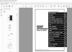
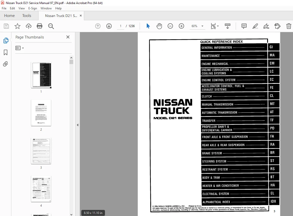
QUICK REFERENCE INDEX1
FOREWORD2
GI – General Information0
MA – Maintenance0
EM – Engine Mechanical0
LC – Engine Lubrication & Cooling Systems0
EC – Engine Control System0
FE – Accelerator Control, Fuel & Exhaust Systems0
CL – Clutch0
MT – Manual Transmission0
AT – Automatic Transmission0
TF – Transfer0
PD – Propeller Shaft & Differential Carrier0
FA – Front Axle & Front Suspension0
RA – Rear Axle & Rear Suspension0
BR – Brake System0
ST – Steering System0
RS – Restraint System0
BT – Body Trim0
HA – Heater & Air Conditioner0
EL – Electrical System0
IDX – Alphabetical Index1
FOLD OUT0
COMMENT SHEET3
QUICK REFERENCE CHART4
GST Mode 6 – Test Value & Test Limit Chart5
MA – Maintenancepdf6
QUICK REFERENCE INDEX0
TABLE OF CONTENTS6
PRECAUTIONS AND PREPARATION7
Supplemental Restraint System (SRS) “AIR BAG”7
Special Service Tool7
GENERAL MAINTENANCE8
PERIODIC MAINTENANCE 10
Schecule 1 11
Schedule 2 12
RECOMMENDED FLUIDS AND LUBRICANTS 13
Fluids and Lubricants 13
SAE Viscosity Number 14
Antifreeze Coolant Mixture Ratio 14
ENGINE MAINTENANCE 15
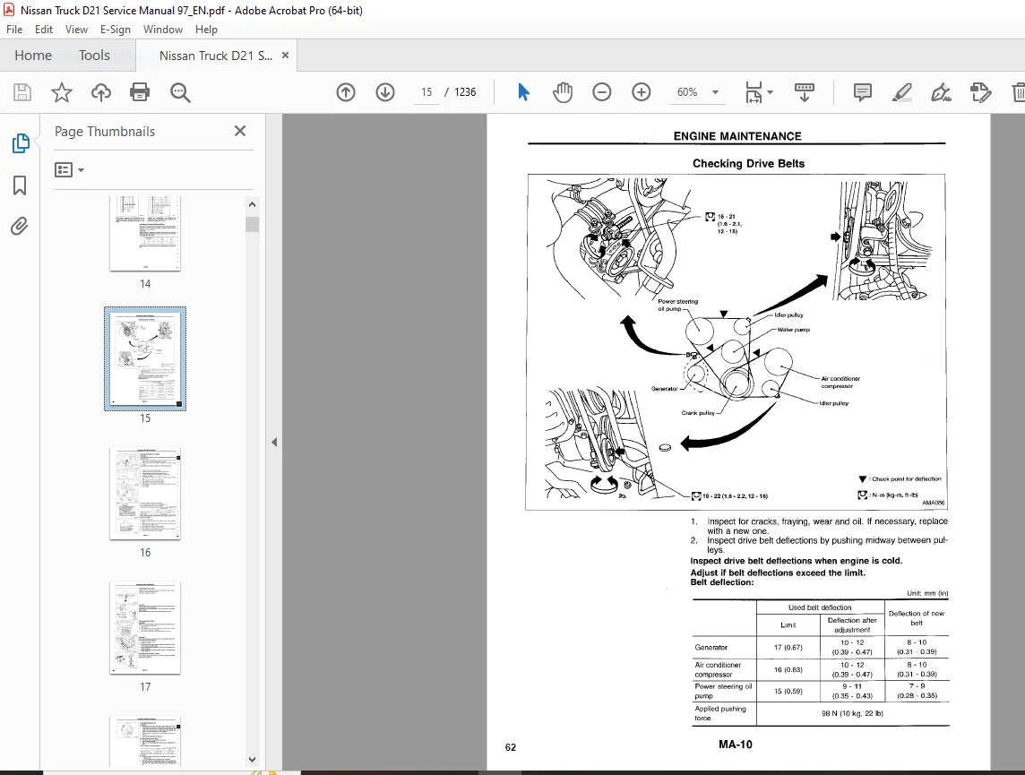
Checking Drive Belts 15
Changing Engine Coolant 16
Checking Fuel Lines 17
Changing Fuel Filter 17
Changing Air Cleaner Filter 17
Changing Engine Oil 18
Changing Oil Filter 18
Changing Spark Plugs 19
Checking EVAP Vapor Purge Lines 20
Changing Positive Crankcase Ventillation (PCV) Filter 20
CHASSIS AND BODY MAINTENANCE 21
Checking Exhaust System 21
Checking Clutch Fluid Level and Leaks 21
Checking M/T Oil 21
Changing M/T Oil 21
Checking Water Entry – For 4WD models 21
Checking A/T Fluid 21
Changint A/T Fluid 22
Checking Transfer Fluid 22
Changing Transfer Fluid 23
Checking Propeller Shaft 23
Checking Differential Gear Oil 23
Changing Differential Gear Oil 24
Balancing Wheels 24
Tire Roataion 24
Checking Brake Fluid Level and Leaks 25
Checking Brake System 25
Checking Disc Brake 25
Checking Drum Brake 25
Checking Steering Gear and Linkage 26
Checking Power Steering Fluid and Lines 26
Checking Steering Gear Oil Level and Leaks 26
Lubricating Hood Latches, Locks and Hinges 27
Checking Seat Belts, Buckles, Retractors, Anchors and Adjusters 28
SERVICE DATA AND SPECIFICATIONS (SDS 29
Engine Maintenance 29
Chassis and Body Maintenance 29
EM – Engine Mechanicalpdf 30
QUICK REFERENCE INDEX0
TABLE OF CONTENTS 30
PRECAUTIONS 31
Supplemental Restraint System (SRS) “AIR BAG” 31
Parts Requiring Angular Tightening 31
Liquid Gasket Application Procedure 31
PREPARATION 32
Special Service Tools 32
Commercial Service Tools 34
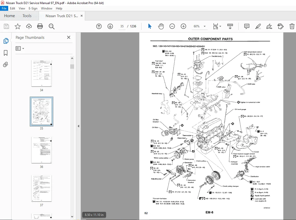
OUTER COMPONENT PARTS 35
COMPRESSION PRESSURE 36
Measurement of Compression Pressure 36
OIL PAN 37
Removal 37
Installation 37
TIMING CHAIN 39
Removal 39
Inspection 40
Installation 41
OIL SEAL REPLACEMENT 43
Valve Oil Seal 43
Front Oil Seal 43
Rear Oil Seal 44
CYLINDER HEAD 45
Removal 46
Disassembly 48
Inspection 48
Assembly 54
Installation 55
ENGINE REMOVAL 58
Removal 59
Installation 60
CYLINDER BLOCK 61
Disassembly 62
Inspection 62
Assembly 68
SERVICE DATA AND SPECIFICATIONS (SDS) 71
General Specifications 71
Inspection and Adjusement 71
GI – General Informationpdf 78
QUICK REFERENCE INDEX0
TABLE OF CONTENTS 78
PRECAUTIONS 79
Precautions for Supplemental Restraint System (SRS) “AIR BAG” 79
General Precautions 80
Precautions for Engine Oils 82
Precautions for Multiport Fuel Injection System or ECCS Engine 83
Precautions for Three Way Catalyst 83
Precautions for Fuel 83
Precautions for Air Conditioning 83
HOW TO USE THIS MANUAL 84
HOW TO READ WIRING DIAGRAMS 86
Sample/Wiring Diagram – EXAMPL – 86
Description 88
Connector Symbols 90
Switch Positions 91
Detectable Lines And Non-Detectable Lines 92
Multiple Switch 92
Foldout Page 93
Wiring Diagram Codes (Cell Codes) 94
HOW TO PERFORM EFFICIENT DIAGNOSIS FOR AN ELECTRICAL INCIDENT 95
Work Flow 95
Incident Simulation Tests 96
Circuit Inspection 100
Introduction 100
Testing for “Opens” In The Circuit 101
Testing for “Shorts” In The Circuit 102
Ground Inspection 103
Voltage Drop Tests 104
HOW TO FOLLOW FLOW CHART IN TROUBLE DIAGNOSES 107
CONSULT CHECKING SYSTEM 110
IDENTIFICATION INFORMATION 111
Model Variation 111
Identification Number 113
Dimensions 115
Wheels & Tires 115
LIFTING POINTS AND TWO TRUCK TOWING 116
Pantograph Jack 116
Screw Jack 116
Garage Jack and Safety Stand 117
2-pole Lift 118
Tow Truck Towing 119
Towing Point 120
TIGHTENING TORQUE OF STANDARD BOLTS 121
SAE J1930 TERMINOLOGY LIST 122
LC – Engine Lubrication & Cooling Systemspdf 126
QUICK REFERENCE INDEX0
TABLE OF CONTENTS 126
PRECAUTIONS AND PREPARATION 127
Supplemental Restraint System (SRS) “AIR BAG” 127
Liquid Gasket Application Procedure 127
Special Service Tools 128
ENGINE LUBRICATION SYSTEM 129
Lubrication Circuit 129
Oil Pressure Check 130
Oil Pump 130
ENGINE COOLING SYSTEM 132
Cooling Circuit 132
System Check 132
Water Pump 133
Thermostat 134
Radiator 136
Cooling Fan 137
Overheating Cause Analysis 138
SERVICE DATA AND SPECIFICATIONS (SDS) 139
Engine Lubrication System 139
Engine Cooling System 139
EC – Engine Control Systempdf 140
QUICK REFERENCE INDEX0
TABLE OF CONTENTS 140
DIAGNOSTIC TROUBLE CODE INDEX 142
Alphabetical & P No Index for DTC 142
PRECAUTIONS AND PREPARATION 144
ENGINE AND EMISSION CONTROL OVERALL SYSTEM 149
Circuit Diagram 149
System Diagram 150
ECCS Component Parts Location 151
Vacuum Hose Drawing 153
System Chart 154
ENGINE AND EMISSION BASIC CONTROL SYSTEM DESCRIPTION 155
Multiport Fuel Injection (MFI) System 155
Distributor Ignition (DI) System 157
Air Conditioning Cut Control 158
Fuel Cut control (at no load & high engine speed 159
EVAPORATIVE EMISSION SYSTEM 160
Description 160
Inspection 160
Evaporative Emission Line Drawing 162
POSITIVE CRANKCASE VENTILATION 164
Description 164
Inspection 164
BASIC SERVICE PROCEDURE 165
Fuel Pressure Release 165
Fuel Pressure Check 165
Injector Removal and Installation 166
Fast Idle Cam (FIC) Inspection and Adjustment 167
Idle Speed/Ignition Timing/Idle Mixture Ratio Adjustment 168
ON BOARD DIAGNOSTIC SYSTEM DESCRIPTION 174
Introduction 174
Two Trip Detection Logic 174
Emission-related Diagnostic Information 175
Malfunction Indicator Lamp (MIL) 185
OBD System Operation Chart 188
CONSULT 193
Generic Scan Tool (GST) 206
TROUBLE DIAGNOSIS – Introduction 208
Introduction 208
Diagnostic Worksheet 208
TROUBLE DIAGNOSIS – Work Flow 210
Work Flow 210
Description for Work Flow 211
TROUBLE DIAGNOSIS – Basic Inspection 212
Basic Inspection 212
TROUBLE DIAGNOSIS – General Description 215
Diagnostic Trouble Code (DTC) Inspection Priority Chart 215
Fail-Safe Chart 216
Symptom Matrix Chart 217
CONSULT Reference Value in Data Monitor Mode 219
Major Sensor Reference Graph in Data Monitor Mode 221
ECM Terminals and Reference Value 223
TROUBLE DIAGNOSIS FOR POWER SUPPLY 229
Main Power Supply and Ground Circuit 229
DTC P0100, Mass Air Flow Sensor (MAFS) 233
DTC P0105, Absolute Pressure Sensor 240
DTC P0110, Intake Air Temperature Sensor 247
DTC P0115, Engine Coolant Temperature Sensor (ECTS) 253
DTC P0120, Throttle Position Sensor 258
DTC P0125, Engine Coolant Temperature (ECT) Sensor 264
DTC P0130, Front Heated Oxygen Sensor (Front HO2S) 269
DTC P0130, Closed Loop Control 274
DTC P0135, Front Heated Oxygen Sensor Heater 275
DTC P0136, Rear Heated Oxygen Sensor (Rear (HO2S) 279
DTC P0141, Rear Heated Oxygen Sensor Heater 283
DTC P0171, Fuel Injection System Function (Lean side) 288
DTC P0172, Fuel Injection system Function (Rich side) 293
DTC P0180, Tank Fuel Temperature Sensor 298
DTC P0300 – P0304, No 4 – 1 Cylinder Misfire, Multiple Cylinder Misfire 302
DTC P0335, Crankshaft Position Sensor (CKPS) (OBD) 306
DTC P0340, Camshaft Position Sensor (CMPS) 311
DTC P0400, EGR Function 316
DTC P0402, EGRC-BPT Valve Function 324
DTC P0420, Three Way Catalyst Function 326
DTC P0440, Evaporative Emission (EVAP) Control System (Small Leak) 329
DTC P0443, Evaporative Emission (EVAP) Canister Purge Control Valve/Solenoid Valve 339
DTC P0446, Evaporative Emission (EVAP) Canister Vent Control Valve 347
DTC P0450, Evaporative Emission (EVAP) Control System Pressure Sensor 352
DTC P0500, Vehicle Speed Sensor (VSS) 357
DTC P0505, Idle Air Control Valve (IACV) – Auxiliary Air Control (AAC) Valve 361
DTC P0510, Closed Throttle Position Switch 366
DTC P0605, Engine Control Module (ECM)-ECCS Control Module 370
DTC P0705, Park/Neutral Position Switch 372
DTC P1105, Manifold Absolute Pressure (MAP)/Barometric Pressure (BARO) Switch Solenoid Valve 377
DTC P1130, Swirl Control Valve Control Solenoid Valve 383
DTC P1165, Swirl Control Valve Vacuum Check Switch 391
DTC P1320, Ignition Signal 396
DTC P1336, Crankshaft Position Sensor (CKPS) (OBD) (COG) 402
DTC P1400, EGRC-Solenoid Valve 407
DTC P1401, EGR Temperature Sensor 411
DTC P1441, Vacuum Cut Valve Bypass Valve 416
DTC P1445, Evaporative Emission (EVAP) Canister Purge Volume Control Valve 421
DTC P1447, Evaporative Emission (EVAP) Control System Purge Flow Monitoring 428
DTC P1550, Torque Converter Clutch Solenoid Valve 435
DTC P1900, Overheat 440
TROUBLE DIAGNOSIS FOR NON-DETECTABLE ITEMS 443
Injector 443
Start Signal 446
Fuel Pump 449
Power Steering Oil Pressure Switch 453
IACV-FICD Solenoid Valve 457
MIL & Data Link Connectors 461
SERVICE DATA AND SPECIFICATIONS 463
General Specfications 463
Inspection and Adjustment 463
FE – Accelerator Control, Fuel & Exhaust Systemspdf 465
QUICK REFERENCE INDEX0
TABLE OF CONTENTS 465
ACCELERATOR CONTROL SYSTEM 466
Adjusting Accelerator Wire 466
FUEL SYSTEM 467
Fuel Tank 467
Fuel Pump and Gauge 470
EXHAUST SYSTEM 471
CL – Clutchpdf 473
QUICK REFERENCE INDEX0
TABLE OF CONTENTS 473
PRECAUTIONS AND PREPARATION 474
Precautions 474
Special Service Tools 474
Commercial Service Tools 474
CLUTCH SYSTEM 475
Clutch Pedal 476
INSPECTION AND ADJUSTMENT 477
Adjusting Clutch Pedal 477
Bleeding Procedure 478
HYDRAULIC CLUTCH CONTROL 479
Clutch Master Cylinder 479
Operating Cylinder 480
Clutch Damper 481
CLUTCH RELEASE MECHANISM 482
CLUTCH DISC AND CLUTCH COVER 484
Clutch Disc 484
Clutch Cover and Flywheel 485
SERVICE DATA AND SPECIFICATIONS (SDS) 486
General Specifications 486
Inspection and Adjustment 486
MT – Manual Transmissionpdf 487
QUICK REFERENCE INDEX0
TABLE OF CONTENTS 487
PREPARATION 488
Special Service Tools 488
Commercial Service Tools 489
ON-VEHICLE SERVICE 490
Replacing Rear Oil Seal – 2WD Model 490
Position Switch Check 490
REMOVAL AND INSTALLATION 491
MAJOR OVERHAUL 493
Case Components 493
Gear Components – 2WD Model 494
Gear Components – 4WD Model 495
Shift Control Components 496
DISASSEMBLY 497
Case Components 497
Shift Control Components 497
Gear Components 498
INSPECTION 501
Shift Control Components 501
Gear Components 501
Gears and Shafts 501
Synchronizers 501
Bearings 502
ASSEMBLY 503
Gear Components 503
Shift Control Components 509
Case Components 510
SERVICE DATA AND SPECIFICATIONS (SDS) 513
General Specifications 513
Inspection and Adjustment 514
AT – Automatic Transmissionpdf 516
QUICK REFERENCE INDEX0
TABLE OF CONTENTS 516
PREPARATION AND PRECAUTIONS 518
Special Service Tools 518
Precautions For Supplemental Restraint System (SRS) “AIR BAG” 520
Precautions 520
OVERALL SYSTEM 521
Circuit Diagram 521
Wiring Diagram 522
Cross-Sectional View 524
Hydraulic Control Circuits 525
Shift Mechanism 526
TROUBLE DIAGNOSIS – Basic Inspection 528
Remarks 528
A/T Fluid Check 528
Road Test 528
Shift Schedule 530
TROUBLE DIAGNOSIS – General Description 532
Symptom Chart 532
TROUBLE DIAGNOSIS FOR DTC P1550 536
Torque Converter Clutch Solenoid Valve 536
TROUBLE DIAGNOSES 538
Component Inspection 538
Final Check 541
TROUBLE DIAGNOSES – A/T Shift Lock System 546
Description 546
Shift Lock System Electrical Parts Location 546
Wiring Diagram 547
Diagnostic Procedure 548
Key Interlock Cable 550
Component Check 551
ON-VEHICLE SERVICE 553
Control Valve Assembly and Accumulators Inspection 553
Rear Oil Seal Replacement 553
Parking Components Inspection 554
Governor Valve 554
Throttle Wire Adjustment 554
Inhibitor Switch Adjustment 555
Manual Control Linkage Adjustment 555
REMOVAL AND INSTALLATION 556
Removal 556
Installation 557
MAJOR OVERHAUL 558
Oil Channel 560
Locations of Needle Bearings, Thrust Washers and Snap Rings 561
DISASSEMBLY 562
Disassembly 562
REPAIR FOR COMPONENT PARTS 573
Oil Pump 573
Control Valve Assembly 577
Control Valve Upper Body 582
Control Valve Lower Body 586
Governor Valve Assembly 588
Parking Gear 588
Reverse Clutch 589
High Clutch 593
Forward and Overrun Clutches 595
Low & Reverse Brake 599
Forward Clutch Drum Assembly 602
Rear Internal Gear and Forward Clutch Hub 604
Band Servo Piston Assembly 606
Parking Pawl Components 610
ASSEMBLY 612
Assembly (1) 612
Adjustment 620
Assembly (2) 622
SERVICE DATA AND SPECIFICATIONS (SDS) 629
General Specifications 629
Specifications and Adjustment 629
Vehicle Speed When Shifting Gears 629
Vehicle Speed When Performing and Releasing Lock-Up 629
Stall Revolution 629
Line Pressure 629
Return Spring 630
Accumulator O-Ring 630
Clutches And Brakes 631
Oil Pump And Low One-Way Clutch 632
Total End Play 632
Parking Gear 632
Reverse Clutch Drum End Play 632
Removal and Installation 632
TF – Transferpdf 633
QUICK REFERENCE INDEX0
TABLE OF CONTENTS 633
PREPARATION 634
Special Service Tools 634
Commercial Service Tools 635
Replacing Oil Seal 636
Center Case Oil Seal 636
Shift Shaft Oil Seal 636
Rear Oil Seal 637
REMOVAL AND INSTALLATION 638
TRANSFER GEAR CONTROL 638
MAJOR OVERHAUL 640
Case Components 640
Gear Components 641
Shift Control Components 642
DISASSEMBLY 643
REPAIR AND COMPONENT PARTS 647
Mainshaft 647
Front Drive Shaft 649
Counter Gear 650
Main Gear 650
Front Case 652
Shift Shaft Oil Seal 652
Front Case Cover 652
Cover Oil Seal 652
Bearing Retainer 653
Oil Catcher 653
Rear Case 653
Rear Oil Seal 653
Air Breather 653
Shift Control Components 654
ASSEMBLY 655
SERVICE DATA AND SPECIFICATIONS (SDS) 662
General Specifications 662
Inspection and Adjustment 662
PD – Propeller Shaft & Differential Carrierpdf 663
QUICK REFERENCE INDEX0
TABLE OF CONTENTS 663
PREPARATION 665
Special Service Tools 665
Propeller Shaft 670
PROPELLER SHAFT 670
On-vehicle Service 672
Removal and Installation 672
Inspection 672
Disassembly 673
Assembly 674
Final Drive 676
ON-VEHICLE SERVICE 676
Front Oil Seal Replacement (Front final drive) 676
Front Oil Seal Replacement (Rear final drive: Model H233B) 676
Rear Cover Gasket Replacement (Rear final drive: Model C200) 677
REMOVAL AND INSTALLATION (Front final drive) 678
REMOVAL AND INSTALLATION (Rear final drive) 679
R180A 680
FRONT FINAL DRIVE 680
DISASSEMBLY 681
Pre-inspection 681
Final Drive Housing 681
Differential Case 683
Extension Tube and Differential Side Shaft 684
INSPECTION 686
Ring Gear and Drive Pinion 686
Differential Case Assembly 686
Bearing 686
ADJUSTMENT 687
Side Bearing Preload 687
Pinion Gear Height and Pinion Bearing Preload 688
Tooth Contact 692
ASSEMBLY 693
Extension Tube and Differential Side Shaft 693
Differential Case 693
Final Drive Housing 694
H190A 698
REAR FINAL DRIVE 698
DISASSEMBLY 699
Pre-inspection 699
Differential Carrier 699
Differential Case 701
INSPECTION 703
Rear Gear and Drive Pinion 703
Differential Case Assembly 703
Bearing 703
LIMITED SLIP DIFFERENTIAL 704
Preparation for Disassembly 704
Disassembly 705
Inspection 705
Assembly 706
ADJUSTMENT 709
Side Bearing Preload 709
Pinion Gear Height 710
Tooth Contact 714
ASSEMBLY 715
Differential Case 715
Differential Carrier 716
C200 720
REAR FINAL DRIVE 720
DISASSEMBLY 721
Pre-Inspection 721
Differenital Carrier 721
Differential Case 723
INSPECTION 725
Ring Gear and Drive Pinion 725
Differential Case Assembly 725
Bearing 725
LIMITED SLIP DIFFERENTIAL 726
Preparation and Disassembly 726
Disassembly 726
Inspection 727
Adjustment 728
Assembly 730
ADJUSTMENT 732
Side Bearing Preload 732
Pinion Gear Height 733
Tooth Contact 737
ASSEMBLY 738
Differential Case 738
Differential Carrier 739
H233B 743
REAR FINAL DRIVE 743
DISASSEMBLY 744
Pre-inspection 744
Differential Carrier 744
Differential Case 746
INSPECTION 748
Ring Gear and Drive Pinion 748
Differential Case Assembly 748
Bearing 748
LIMITED SLIP DIFFERENTIAL 749
Preparation and Disassembly 749
Disassembly 749
Inspection 750
Adjustment 751
Assembly 752
ADJUSTMENT 755
Pinion Gear Height 755
Tooth Contact 758
ASSEMBLY 759
Differential Case 759
Differential Carrier 760
SERVICE DATA AND SPECIFICATIONS (SDS) 763
Propeller Shaft 763
Final Drive 765
General Specifications 765
Inspection and Adjustment (R180A) 766
Inspection and Adjustment (H190A) 767
Inspection and Adjustment (C200) 768
Inspection and Adjustment (H233B) 769
FA – Front Axle & Front Suspensionpdf 771
QUICK REFERENCE INDEX0
TABLE OF CONTENTS 771
PRECAUTIONS AND PREPARATION 772
Precautions 772
Special Service Tools 772
Commercial Service Tools 772
FRONT AXLE AND FRONT SUSPENSION 773
ON-VEHICLE SERVICE 775
Front Axle and Front Suspension Parts 775
Front Wheel Bearing 776
Preload Adjustment (2WD) 776
Preload Adjustment (4WD) 777
Front Wheel Alignment 778
Preliminary Inspection 778
Camber, Caster and Kingpin Inclication 779
Adjustment 779
Toe-In 782
Front Wheel Turning Angle 783
Drive Shaft 784
FRONT AXLE 785
FRONT AXLE (4WD) 787
Manual-lock Free-running Hub 787
Auto-lock Free-running Hub 788
FRONT AXLE 794
Wheel Hub and Rotor Disc 794
Knuckle Spindle 795
FRONT AXLE (4WD) 798
Drive Shaft 798
FRONT SUSPENSION 804
Shock Absorber 806
Torsion Bar Spring 806
Stabilizer Bar 809
Upper Link 810
Tension Rod or Compression Rod 812
Lower Link 813
Upper Ball Joint and Lower Ball Joint 814
SERVICE DATA AND SPECIFICATIONS 815
General Specifications 815
Inspection and Adjustment 816
RA – Rear Axle & Rear Suspensionpdf 819
QUICK REFERENCE INDEX0
TABLE OF CONTENTS 819
PRECAUTIONS AND PREPARATION 820
Precautions 820
Special Service Tools 820
Commercial Service Tools 820
REAR AXLE AND REAR SUSPENSION 821
ON-VEHICLE SERVICE 822
Rear Axle and Rear Suspension Parts 822
Rear Wheel Bearing 822
REAR AXLE 823
Components 823
Removal 823
Inspection 825
Installation 825
REAR SUSPENSION 827
Shock Absorber 828
Leaf Spring 828
SERVICE DATA AND SPECIFICATIONS (SDS) 830
General Specifications 830
Inspection and Adjustment 830
BR – Brake Systempdf 831
QUICK REFERENCE INDEX0
TABLE OF CONTENTS 831
PRECAUTIONS AND PREPARATION 832
Supplemental Restraint System (SRS) “AIR BAG” 832
Commercial Service Tools 833
CHECK ADJUSTMENT 834
Checking Brake Fluid Level 834
Checking Brake Line 834
Changing Brake Fluid 834
AIR BLEEDING 835
Bleeding Procedure 835
BRAKE HYDRAULIC LINE 836
CONTROL VALVE 838
Proportioning Valve (4WD) 838
Load Sensing Valve (2WD) 839
BRAKE PEDAL AND BRACKET 841
Adjustment 842
MASTER CYLINDER 843
BRAKE BOOSTER 846
On-vehicle Service 846
VACUUM HOSE 848
FRONT DISC BRAKE 849
Pad Replacement 849
REAR DRUM BRAKE 854
PARKING BRAKE CONTROL 858
Adjustment 859
REAR WHEEL ANTI-LOCK BRAKE SYSTEM 860
Purpose 860
Operation 860
System Description 860
System Components 861
Hydraulic Circuit 861
Removal and Installation 862
TROUBLE DIAGNOSIS 863
How to Perform Trouble Diagnoses for Quick and Accurate Repair 863
Symptom Chart 864
Preliminary Check 1 865
Self-diagnosis 866
Component Parts and Harness Connector Location 867
Circuit Diagram 868
Wiring Diagram – ABS – 869
Diagnostic Procedures 871
Electrical Components Inspection 879
SERVICE DATA AND SPECIFICATIONS (SDS) 880
General Specifications 880
Inspection and Adjustment 881
ST – Steering Systempdf 882
QUICK REFERENCE INDEX0
TABLE OF CONTENTS 882
PRECAUTIONS AND PREPARATION 883
Supplemental Restraint System (SRS) “AIR BAG” 883
Steering System 883
Special Service Tools 884
Commercial Service Tool 885
ON-VEHICLE SERVICE 886
Steering System 886
Checking and Adjusting Drive Belts (For power steering) 886
Checking Fluid Level 886
Checking Fluid Leakage 887
Bleed Hydraulic System 887
Checking Steering Wheel Turning Force (For power steering) 888
Checking Steering Wheel Play 888
Checking Neutral Position on Steering Wheel 889
Checking Front Wheel Turning Angle 889
Checking Hydraulic System 889
STEERING WHEEL AND STEERING COLUMN 891
Steering Wheel 891
Steering Column 892
Disassembly and Assembly 893
Inspection 894
MANUAL STEERING GEAR (Model: VB66K) 895
Removal and Installation 895
Disassembly 896
Assembly and Adjustment 896
Inspection 899
POWER STEERING SYSTEM (Model: PB59K) 901
Description 901
POWER STEERING GEAR (Model: PB59K) 902
Removal and Installing 902
Power Steering Gear Component 902
Pre-disassembly Inspection and Adjustment 903
Disassembly 904
Assembly 905
POWER STEERING SYSTEM (Model: PB48S) 908
Description 908
POWER STEERING GEAR (Model: PB48S) 909
Removal and Installing 909
Power Steering Gear Component) 909
Pre-disassembly Inspection and Adjustment 910
Disassembly 911
Assembly 913
POWER STEERING OIL PUMP 916
Disassembly and Assembly 916
Pre-disassembly Inspection 916
Inspection 917
Disassembly 917
Assembly 918
STEERING LINKAGE 919
Removal and Installation 919
Disassembly 920
Inspection 921
SERVICE DATA AND SPECIFICATIONS (SDS) 922
General Specifications 922
Inspection and Adjustment 922
RS – Restraint Systempdf 925
QUICK REFERENCE INDEX0
TABLE OF CONTENTS 925
PRECAUTIONS 926
Supplemental Restraint System (SRS) “AIR BAG” 926
SEAT BELTS 927
Front Seat Belt 928
Rear Seat Belt 929
SUPPLEMENTAL RESTRAINT SYSTEM (SRS) 930
Precautions for SRS “Air Bag” Service 930
Special Service Tools 930
Description 931
SRS Component Parts Location 932
Maintenance Items 932
Diagnosis Sensor Unit and Crash Zone Sensor 933
Removal and Installation 933
Air Bag Module and Spiral Cable 934
Removal 934
Installation 935
Disposal of Air Bag Module 937
Checking Deployment Tool 937
Deployment Procedures for Air Bag Module (Outside of Vehicle) 938
Deployment of Air Bag Module While Mounted In Vehicle 939
Disposing of Air Bag Module 939
TROUBLE DIAGNOSES – Supplemental Restraing System (SRS) 941
How to Perform Trouble Diagnoses for Quick and Accurate Repair 941
Schematic 943
Wiring Diagram – SRS – 944
Self-diagnosis 946
Diagnostic Procedures 946
Trouble Diagnoses for Air Bag Warning Lamp 959
Diagnostic Procedures 959
COLLISION DIAGNOSIS 961
SRS Inspection 961
BT – Body & Trimpdf 962
QUICK REFERENCE INDEX0
TABLE OF CONTENTS 962
PRECAUTIONS 963
Supplemental Restraint System (SRS) “AIR BAG” 963
GENERAL SERVICING 964
Clip and Fastener 964
BODY END 967
Front End 967
Rear End 968
Step Bumper 969
DOOR 970
Front Door 970
INSTRUMENT PANEL 971
INTERIOR TRIM 974
Side and Floor Trim – Passenger room 974
Roof Trim 976
EXTERIOR 978
SEAT 984
Front Seat 984
Jump Seat – King Cab Model 985
SUNROOF 986
Service Procedure 986
WINDSHIELD AND WINDOWS 987
Windshield 988
Back Window 989
Rear Side Window 990
MIRROR 991
Door Mirror 991
Rearview Mirror 992
CAB AND REAR BODY 993
Removal 993
Cab Body 993
Rear Body 993
Body Mounting 994
BODY ALIGNMENT 995
Engine Compartment 996
Underbody 997
HA – Heater & Air Conditionerpdf1004
QUICK REFERENCE INDEX0
TABLE OF CONTENTS1004
PRECAUTIONS AND PREPARATION1005
Precautions for Supplemental Restraint System (SRS) “AIR BAG”1005
Introduction1006
Precautions for Working with R-134a1007
General Refrigerant Precautions1007
Precautions for Refrigerant Connection1008
Precautions for Servicing Compressor1009
Special Service Tools1009
R-134a Service Tools and Equipment1010
Precautions for Service Equipment1012
DESCRIPTION1014
Refrigeration Cycle1014
Component Layout1015
Discharge Air Flow1016
Control Operation1017
TROUBLE DIAGNOSES1018
How to Perform Trouble Diagnoses for Quick and Accurate Repair1018
Operational Check1019
Symptom Chart1021
Preliminary Check1022
Performance Test Diagnoses1025
Performance Chart1027
Trouble Diagnoses for Abnormal Pressure1028
Harness Layout1031
Circuit Diagram1032
Wiring Diagram – HEATER-1033
Wiring Diagram – A/C -1034
Mail Power Supply and Ground Circuit Check1036
Diagnostic Procedure 11037
Electrical Components Inspection1044
Control Linkage Adjustment1045
SERVICE PROCEDURES1047
Checking Refrigerant Leaks1047
Refrigerant Lines1050
R-134a Service Procedure1051
Compressor Luibricant Quantity1053
Compressor Mounting1055
Belt Tension1055
Fast Idle Control Device (FICD)1055
Condenser1055
Compressor1056
Compressor Clutch1056
Thermal Protector1059
SERVICE DATA AND SPECIFICATIONS (SDS)1060
General Specifications1060
Inspection and Adjustment1060
EL – Electric Systempdf1061
QUICK REFERENCE INDEX0
TABLE OF CONTENTS1061
PRECAUTIONS1063
Supplemental Restraint System (SRS) “AIR BAG”1063
HARNESS CONNECTOR1064
STANDARDIZED RELAY1065
POWER SUPPLY ROUTING1067
Schematic1067
Wiring Diagram – POWER -1068
Fuse1072
Fusible Link1072
Circuit Breaker Inspection1072
GROUND DISTRIBUTION1073
BATTERY1076
How to Handle Battery1076
Service Data Specifications (SDS)1079
STARTING SYSTEM1080
System Description1080
Wiring Diagram – START -1081
Starter1083
Pinion/Clutch Check1085
Service Data and Specifications (SDS)1085
CHARGING SYSTEM1086
System Description1086
Wiring Diagram – CHARGE -1087
Trouble Diagnoses1088
Generator1089
Diode Check1090
Disassembly and Assembly1091
Service Data and Specifications (SDS)1092
COMBINATION SWITCH1093
Combination Switch/Check1093
Combination Switch/Replacement1094
Steering Switch/Check1095
HEADLAMP1096
System Description (For USA)1096
Wiring Diagram (For USA) – H/LAMP -1097
Trouble Diagnoses (For USA)1098
System Description (For Canada)1099
Operation (Daytime light system for Canada)1100
Schematic (For Canada)1101
Wiring Diagram (For Canada) – DTRL -1103
Trouble Diagnoses (For Canada)1106
Bulb Specifications1108
Aiming Adjustment1108
EXTERIOR LAMP1110
Back-up Lamp/Wiring Diagram – BACK/L -1110
Parking, License, Tail and Stop Lamps/Wiring Diagram – TAIL/L -1111
Turn Signal and Hazard Warning Lamps/System Description1113
Turn Signal and Hazard Warning Lamps/Wiring Diagram – TURN -1115
Turn Signal and Hazard Warning Lamps/Trouble Diagnoses1117
Combination Flasher Unit Check1117
Bulb Specifications1118
INTERIOR LAMP1119
Illumination/System Description1119
Illimunation/Schematic1120
Illimunation/Wiring Diagram, – ILL -1121
Interior and Map Lamps/Wiring Diagram – INT/L -1124
Bulb Specifications1125
METERS AND GAUGES1126
Start Description1126
Combination Meter1127
Speedometer, Tachometer, Temp, and Fuel Guages/Wiring Diagram – METER -1129
Inspection/Water Temperature Guage1130
Inspection/Fuel Guage1131
Inspection/Tachometer1132
Inspection/Speedometer and Vehicle Speed Sensor1133
Inspection/Speedometer and Fuse 1134
Fuel Tank Guage Unit Check1135
Fuel Warning Lamp Sensor Check1135
Thermal Transmitter Check1135
Oil Pressure Switch Check1135
Vehicle Speed Sensor Signal Check1136
WARNING LAMPS1137
System Description1137
Schematic1139
Wiring Diagram – WARN -1140
Diode Check1143
WARNING CHIME1144
System Description1144
Wiring Diagram – CHIME -1145
Trouble Diagnoses1146
WIPER AND WASHER1153
System Description1153
Wiring Diagram – WIPER -1155
Trouble Diagnoses1157
Wiper Amplifier Check1160
Installation1160
Washer Nozzle Adjustment1161
HORN, LIGHTER, CLOCK1162
Wiring Diagram – HORN -1162
AUDIO1163
System Description1163
Schematic1164
Wiring Diagram – AUDIO -1165
Trouble Diagnoses1168
ANTENNA1170
Location of Antenna1170
Window Antenna Repair1171
MIRROR1173
Wiring Diagram – MIRROR -1173
AUTOMATIC SPEED CONTROL DEVICE (ASCD)1175
Component Parts and Harness Connector Location1175
System Description1176
Schematic1178
Wiring Diagram – ASCD -1179
Trouble Diagnoses1184
POWER WINDOW1196
Component Layout1196
System Description1197
Wiring diagram – WINDOW -1199
Trouble Diagnoses1201
POWER DOOR LOCK1202
System Description1202
Schematic1203
Wiring Diagram – D/LOCK -1205
Trouble Diagnoses1207
LOCATION OF ELECTRICAL UNITS1211
Passenger Compartment1211
Engine Compartment1212
HARNESS LAYOUT1213
How To Read Harness Layout1213
Outline1214
Main Harness and Air Bag Harness1215
Instrument Harness1219
Engine Harness1220
Chassis and Tail Harness1221
Front Door Harness1222
Room Lamp Harness1223
Foldoutpdf1224
QUICK REFERENCE INDEX0
ELECTRICAL SYSTEM1
SUPER MULTIPLE JUNCTION (SMJ)1224
INSTALLATION1224
Terminal Arrangement1225
JOINT CONNECTOR (J/C)1226
Location1226
FUSE BLOCK1227
Fuse Arrangement1227
CONTROL UNITS/MODULE1228
IDX – Indexpdf1229
QUICK REFERENCE INDEX0
DESCRIPTION:
Nissan Truck D21 Series Service Manual – PDF DOWNLOAD
FOREWORD:
- This manual contains maintenance and repair procedures for the 1997 Nissan TRUCK. In order to assure your safety and the efficient functioning of the vehicle, this manual should be read thoroughly.
- It is especially important that the PRECAUTIONS in the GI section be completely understood before starting any repair task. All information in this manual is based on the latest product information at the time of publication.
- The right is reserved to make changes in specifications and methods at any time without notice.
GENERAL MAINTENANCE:
- General maintenance includes those items which should be checked during the normal day-to-day operation of the vehicle. They are essential if the vehicle is to continue operating properly.
- The owners can perform checks and inspections themselves or they can have their NISSAN dealers do them.
G.B 26/02/25