O & K WHEEL LOADER MODEL 1500 ZTB107 PARTS MANUAL – PDF DOWNLOAD
Original price was: $78.95.$21.95Current price is: $21.95.
O & K WHEEL LOADER MODEL 1500 ZTB107 PARTS MANUAL – PDF DOWNLOAD
Serial No. 3121401& Higher
Engine Model: Deutz F5L-912.
Description
O & K WHEEL LOADER MODEL 1500 ZTB107 PARTS MANUAL – PDF DOWNLOAD
FILE DETAILS:
O & K WHEEL LOADER MODEL 1500 ZTB107 PARTS MANUAL – PDF DOWNLOAD
Format: PDF
Language: English
O & K WHEEL LOADER MODEL 1500 ZTB107 PARTS MANUAL – PDF DOWNLOAD:
DESCRIPTION:
O & K WHEEL LOADER MODEL 1500 ZTB107 PARTS MANUAL – PDF DOWNLOAD
Serial No. 3121401& Higher
Engine Model: Deutz F5L-912.
INTRODUCTION:
- This manual illustrates and identifies maintenance parts for the Model 1500 loader, to enable you to determine the part number and name assigned to the part you wish to order. Ordering by proper part number and name will help ensure the receipt of the proper part for the first time without time-consuming exchanges of correspondence or other annoying delays.
- An index is provided in the front of this manual to help you determine which illustration contains the part you want to order. Determine the basic system or assembly in which the part is used, and find this system or assembly in the Index. It will reference the pages which illustrate and list the part.
- This manual contains the latest information available at the time of printing. However, at the discretion of O & K Trojan Industries. its contents are subject’ to change .without notice. This reservation is in keeping with the Company’s policy of constant progressive improvement and refinement of all of our products. As a result of such policy, certain changes may be made from time to time which will not be covered in this manual.
- This manual has been indexed by group numbers, which identifies the « area of the machine that requires servicing. The first two digits in the group numbers indicates the area of the machine.
Example: Group 32 05 01
32 – Indicates – Hydraulic System
05 – Indicates — Hydraulic Tank Assembly
01 – Indicates – Hydraulic Filter
These group numbers are for easy reference only.
The group numbers are provided for easy access to the area in which the part is used. Find the basic group number, turn to the illustration and find the part (item number) you want to order.
Because we are constantly upgrading our equipment, it is necessary“ that the SERIAL NUMBER of your machine accompany every repair parts order. To assure the receipt of the proper part, it is essential that the following information be included with your parts order:
- MACHINE MODEL NUMBER
- MACHINE SERIAL NUMBER
- PART NUMBER OF THE DESIRED PART
- PART NAME OF THE DESIRED PART
- QUANTITY OF ITEMS WANTED
- NAME AND ADDRESS TO WHICH PART SHOULD BE SENT
USE ONLY PARTS WHICH ARE AUTHORIZED.BY O a K TROJAN INDUSTRIES TO ENSURE THAT’ ORIGINAL“ DEPENDABILITY AND, PERFORMANCE WILL BE MAINTAINED. ‘
TABLE OF CONTENTS:
O & K WHEEL LOADER MODEL 1500 ZTB107 PARTS MANUAL – PDF DOWNLOAD
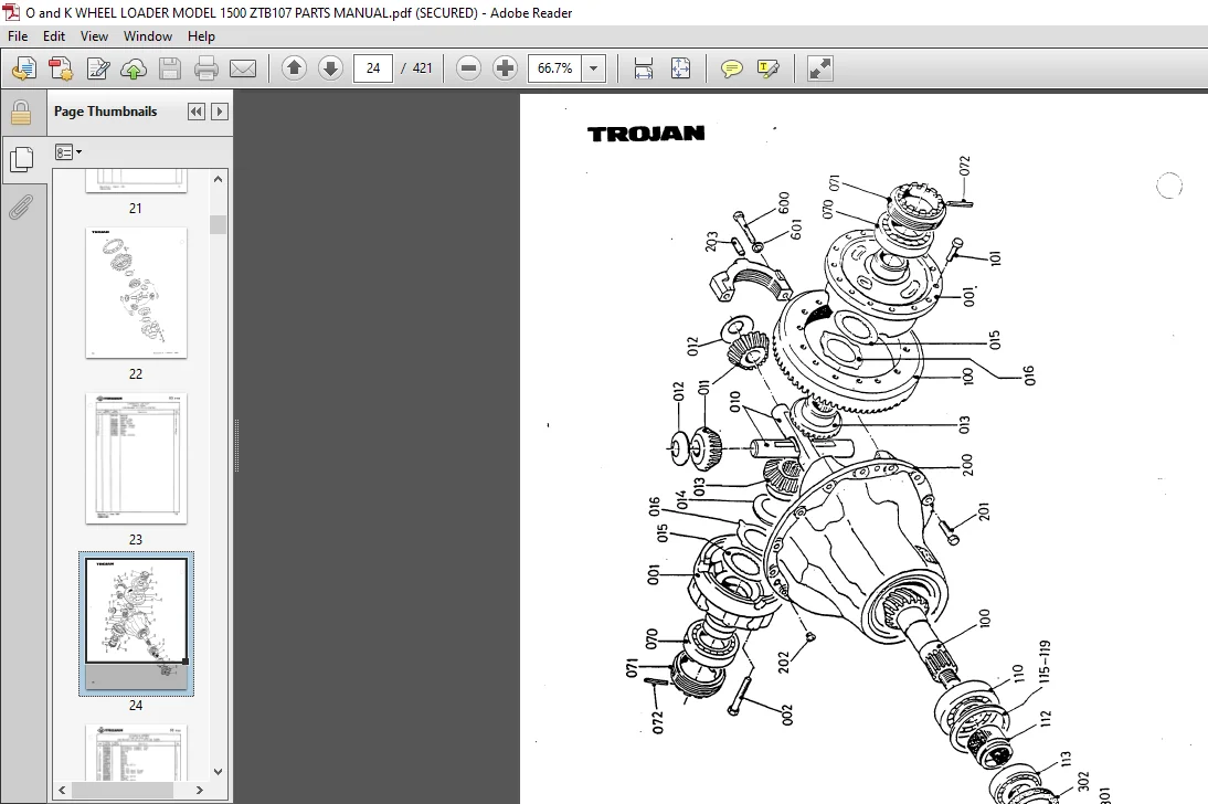
Axles Group
3100 – Front Axle
3101 – Differential Case And Ring Gear Thru SIN 3123100
– S/H 3123101 and Higher
3102 – Differential Case Thru S/N 3122002
– S/N 3122101 – 3123100
– S/N 3123101 and Higher
3103 – Housing and Shaft Assembly
3104 – Planetary Hub Assembly Thru S/N 3123100
– S/N 3123101 and Higher
3105 – Brakes Group Thru S/N 3123100
– S/N 3123101 and Higher
3200 – Rear Axle .
– Rear Axle (State of Mass.)
3201 – Housing and Planetary Hub (State of Mass.)
3202 – Brake GrOup Thru S/H 3123100
~ S/N 3123101 and Higher
r State of Mass.
3203 – Differential Assembly (State of Mass.)
3204 – Differential Case and Gear (State of Mass.)
Axle Mounting Group ‘
1100 – Front & Rear
Engine, Controls & Filters Group See Engine 3
Transmission Torque Converter Group
0000 – Transmission Hounting
0100 – Transmission Hydraulic System
1001 – Transmission/Torque Converter Assembly – Housing Group
1002 – Torque Converter
1003 – Turbine Shaft, Stator Support and Baffle Group
1004 – Drive Plate Group
1005 – Auxiliary Pump Drive Group
1006 – Charging Pump GrOup
1007 – Forward Clutch Group
1008 – Reverse and 2nd Clutch Group
1009 – Low Speed Clutch Group
1010 – 3rd Speed Clutch Group
1011 – Reverse Idler Group
1012 – Idler Shaft and Steer Pump Group
1013 – Output Shaft Group
1014 – Pump/Filter Group
1015 ~ Control Valve Assembly
1016 – Modular Valve Assembly
1017 – Parking Brake Group
Steering Group
0000 — Hydraulic System
0001 – Cylinder, Steer
0002 – Steering Gear, Hydraulic
Propeller Shafts Group
0000 – Propeller Shafts & Linkage
Transmission Controls Group
0000 – Parking Brake Linkage
0100 – Transmission Controls
Automatic Bucket Leveler Group
6200 – S/N 3122101 thru S/N 3124220
– S/N 3124601 and Higher
Brake System Group
2000 – Brake Controls & Lines
2001 – Brake Valve Installation – 1 Pedal
2002 – Brake Valve Installation – 2 Pedal
Electrical System Group
0000 – Battery 8 Wiring Diagram (24V)
0001 – Lights 8 Electrical Components
0002 – Battery Box
0003 – Instruments & Switches
0004 – Oil Pressure Gauge (12V)
0900 – Worklight/Installation
2700 — Ventilator, Hoof
3300 – windshield Wiper, Rear
3400 – Speedometer/Installation
3700 – Tachometer
Bucket Indicator Group
0300 – Bucket Indicator
Sheet Metal – Engine Group
0200 – Hood Assembly
1300 – Hood Panel & Acoustical Installation
1400 – Acoustical Installation, Engine
Fenders 6 Mudflaps Group
0000 – Fenders. Front 6 Rear
0001 – Fenders. Front
Fuel Tank Group
2000 – Fuel Tank Installation
Wheels 6 Tires Group ‘
0000 – Tires 6 wheels
Cab Group
1400 – Floorplates
1600 – Cab “ROPS” STD
– Cab Assembly (Hi Visibility)
1601 – Cab Body Assy. 6 Cab Door Assemblies
1602 – Cab Door Assemblies
1603 – Can Interior/Acoustics (S/N 3122100 and Higher)
2200 – Seat Assy. 5 Mounting
2201 – Seat Mounting
2202 – Seat Assembly
3500 – Acoustical Installation. Cab (Thru S/N 3122099)
Tools Group
0000 – Tools 4
Tank Covers Group
0100 – Covers, Step Plate
0300 – Chock Mounting, Wheel
0600 – Shroud Mounting
1500 – Support Mounting, Light
Heater Group
0000 – Heater System
0001 – Heater Assembly (ESPAR)
Hydraulic System Group
0500 – Reservoir, Hydraulic
0501 – Filter, Hydraulic Oil
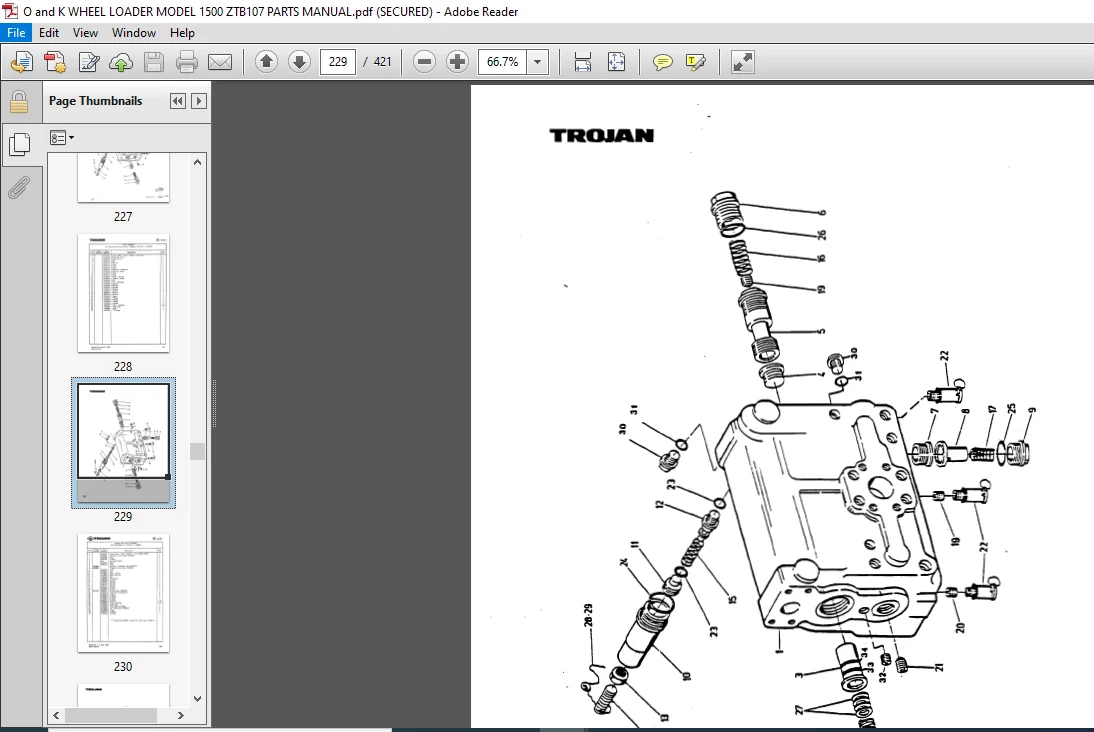
4000 – Hydraulic System, Main ‘
4001 – Valve Assy., Control
4002 – Linkage, Valve Control
4003 – Valve Assy., Control
4004 – Gear Pump
3rd Function Hydrailucs
3000 – Air EleCtrical – Thru SIN 3122099
– SIN 3122099 thru 3124600
3001 – Va1Ve, Change Over SIN 3122101 – 3124600
3100 – Mechanical/Hydraulic S/N 3124601 and Up
3101 – Lift Arm Piping
3200 – Valve Controls
Counterweight Group ‘
0100 – Counterweight
Lift Arms Group
0000 – Lift Arm Linkage (Incl. Optional High Lift Arms)
0001 – Cylinder, Bucket
0002 – Cylinder, Lift (Incl. Optional Cylinder)
5000 – Bucket Assy.
5200 – Bucket Attachments.
Miscellaneous Group
0700 – Injector, Alcohol
1200 – Injector, Alcohol
1201 – Safety Walk Installation
1202 ~ DEFRDSIER
1203 – Lock, Hydraulic Control Lever
1204 – Lock, Lift Arm
1205 – Windshield Wiper, Rear (Optional)
IMAGES PREVIEW OF THE MANUAL:
PLEASE NOTE:
- This is the SAME exact manual used by your dealers to fix your vehicle.
- The same can be yours in the next 2-3 mins as you will be directed to the download page immediately after paying for the manual.
- Any queries / doubts regarding your purchase, please feel free to contact [email protected]