Ohmeda Infant Warmer Service Manual Models 2001-5000 Repair PDF
Original price was: $120.00.$16.95Current price is: $16.95.
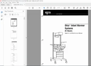
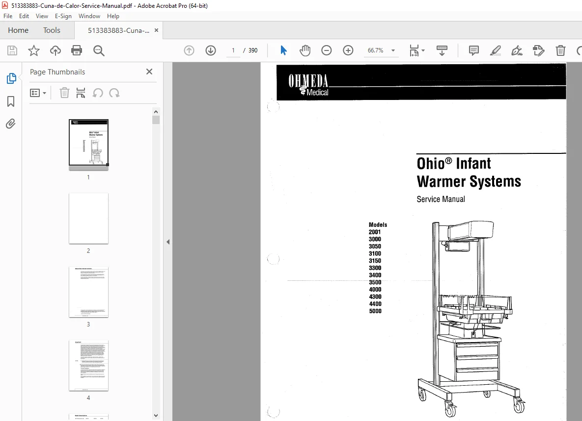
Complete technical service manual for Ohmeda Ohio® Infant Warmer Systems covering models 2001, 3000, 3050, 3100, 3150, 3300, 3400, 3500, 4000, 4300, 4400, and 5000. Professional repair guide with functional descriptions, calibration procedures, circuit diagrams, and troubleshooting for neonatal intensive care radiant warmers. Includes control board schematics, power supply diagnostics, temperature sensor calibration, heater control systems, and complete disassembly instructions for NICU equipment maintenance.
Description
Ohmeda Infant Warmer Service Manual Models 2001-5000 Repair Guide – PDF DOWNLOAD
DESCRIPTION
This comprehensive Ohmeda Ohio® Infant Warmer Systems Service Manual provides complete technical documentation for servicing and repairing multiple warmer models used in neonatal intensive care units (NICU), labor and delivery (L&D), and nursery environments. This professional-grade manual is essential for biomedical technicians, hospital maintenance staff, and authorized service personnel working on infant radiant warming equipment.
Models Covered
This service manual includes detailed technical information for the following Ohmeda infant warmer models:
- Model 2001 IWS – International manual mode warmer with integral infant bed for short-term attended care in OR and L&D
- Model 3000 IWS – Free-standing warmer for use over various infant bassinets
- Model 3050 IWS – Wall-mounted heater head only
- Model 3100 IWS – Wall-mounted heater with dovetail rails
- Model 3150 IWS – Wall-mounted heater with rails and integral bed
- Model 3300 IWS – Free-standing with integral bed for procedures and long-term care
- Model 3400 IWS – Similar to 3300 with elevating pedestal
- Model 3500 IWS – Free-standing with detachable bassinet for long-term care
- Model 4000 IWS – Free-standing warmer for general nursery and post-operative applications
- Model 4300 IWS – Large bed warmer for surgical procedures
- Model 4400 IWS – Large bed with elevating pedestal, narrow footprint
- Model 5000 IWS – Large bed with elevating pedestal for surgical procedures
Technical Content Overview
Section 1: Functional Descriptions
Control Board Systems – Detailed technical analysis of three control board versions:
- Control Board 6600-0521-700 with microcontroller architecture, memory allocation, line frequency circuits, watchdog timer, and temperature measurement systems
- Control Board 6600-0218-700 specifications
- Control Board 6600-0048-700 with analog-to-digital converter calibration procedures
Temperature Measurement & Control:
- Analog input circuits and reference voltage specifications
- Multiplexer (MUX) configuration
- A/D converter operation and start-up self-test procedures
- Heater control algorithms for manual and servo modes
- Calculating and monitoring heater cycles
- Override signals for safety protection
Display Board Systems:
- Display Board 0631-5031-700 specifications
- Switch decoding circuits
- LED display drivers and brightness adjustment
- Multiplexing display operations
Power Supply Boards – Complete technical data for multiple versions:
- Power Supply 6600-0330-700 with 5V and 9V circuits
- Power Supply 6600-0179-700 specifications
- Power Supply 6600-0181/183-700 with motor control
- Line voltage sensing and compensation
- Safety relay circuits
- Observation light and alarm light control
- Heater status and control circuits
ThermaLink Communication Option:
- Older communication boards with test switch
- Newer communication boards without test switch
- Interface protocols and connectivity
Section 2: Setup and Checkout Procedures
Mechanical Checkout:
- Overall appearance inspection protocols
- Heater rotation verification
- Mechanical integrity checks
- Warmer/bassinet interlock testing (Model 3500)
- Warmer/bassinet unlock procedures
- Heater and bed height adjustment procedures
Control Module:
- Removal procedures
- Replacement and verification
- Access protocols for calibration
Section 3: Height Adjustment Procedures
- Lowering heater and bed height
- Control module removal and replacement
- Adjustment specifications and tolerances
Section 4: Calibration and Adjustment
Maintenance Schedule – Recommended calibration intervals and preventive maintenance
Controller Calibration (Software Revision 06.00 or Higher):
- Control unit access procedures
- Power supply board voltage verification (±5V, ±9V circuits)
- Display brightness check and adjustment
- Alarm volume calibration and adjustment procedures
- Analog-to-Digital Converter (ADC) calibration with verification tests
- ADC adjustment using Ohmeda temperature simulator box
- ADC adjustment using 0.1% accurate resistance decade box
- Line voltage compensation adjustment
Controller Calibration (Software Revision 04.01 through 05.10):
- Legacy software calibration procedures
- Backward compatibility instructions
- Modified test procedures for older firmware
Additional Calibration Tests:
- Safety circuit testing (prior to revision 03.11)
- Triac safety circuit test (revision 03.11 software)
- Test loop procedures for complete unit testing
- Controller unit testing separate from warmer
- Gas regulator checks
Electrical Safety Verification:
- Leakage current measurements and acceptable limits
- Ground resistance verification
- Bed motor raise and lower testing (elevating models only)
Section 5: Repair and Disassembly
Heater Module Repairs:
- Heater housing disassembly for units with HAK, HAJ, AAN, HCA serial numbers
- Heater housing disassembly for units with HCC serial numbers
- Heater element replacement procedures
- Heater housing reassembly with proper alignment
- Component testing after replacement
Elevating Base Systems:
- Electric motor/jack-shaft disassembly and reassembly
- Motor replacement with torque specifications
- Jack mechanism replacement
- Capacitor replacement for motor circuits
- Power cord replacement procedures
- Column guide lubrication on Type 1 units
Key Features of This Manual
✓ Surface Mount Technology (SMT) Updates – Information on new control and display boards with SMT components versus older through-hole mounted boards
✓ Software Revision Identification – Guidance on identifying control board revision level 06.00 by 12-pin test connector (earlier boards have 7-pin connector)
✓ Dual Board Coverage – Functional descriptions for both recent production and previously manufactured warmer units
✓ Static Control Warnings – Comprehensive ESD protection procedures throughout the manual
✓ Connector & Test Point Diagrams – Complete pin-out diagrams and voltage specifications
✓ Jumper Configurations – Description and values for all jumper settings
✓ Copyright 1998 Ohmeda Medical – Official manufacturer documentation
Safety Precautions & Symbols
The manual includes comprehensive safety guidelines:
- CAUTION symbols for potential equipment damage scenarios
- WARNING symbols for patient or operator injury risks
- Static Control Precaution symbols for ESD-sensitive procedures
- Type B equipment classifications
- Protective and functional earth terminal identification
- Alarm silence and power control symbols
Technical Competence Requirements
This manual is designed for trained and authorized service personnel with general knowledge and experience with neonatal medical devices. All procedures require proper tools, test equipment, and genuine Ohmeda replacement parts.
File Details
Manual Name: Ohmeda Ohio® Infant Warmer Systems Service Manual
Document Number: 6600-0195-000
Revision Date: October 1998
Models Covered: 2001, 3000, 3050, 3100, 3150, 3300, 3400, 3500, 4000, 4300, 4400, 5000
Total Pages: 390 pages
PDF Quality: High-quality scanned document, OCR-compatible
File Size: 11.0 MB
Format: Searchable PDF