
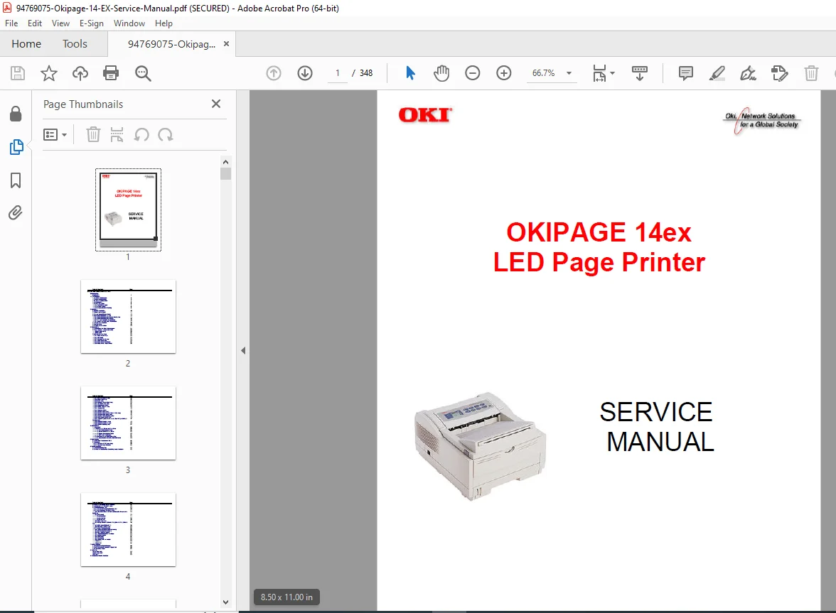
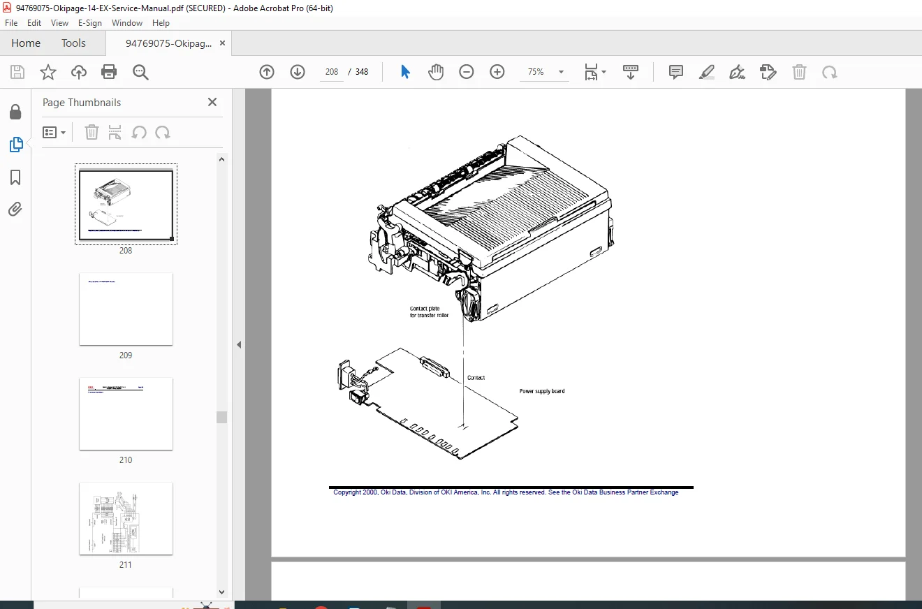
OKIPAGE 14ex LED Page Printer Service & Electrophotographic Process Guide PDF
Original price was: $85.00.$18.95Current price is: $18.95.
This is the comprehensive OKIPAGE 14ex LED Page Printer Service Manual detailing the system architecture, component operation, and repair procedures. It thoroughly explains the OKIPAGE 14ex electrophotographic process voltage values for the charge, developing, transfer, and fusing sections. Technicians can use detailed flowcharts for diagnostics, including troubleshooting OKIPAGE 14ex cyclical defect issues and other image problems. Essential adjustment procedures are covered,
such as OKIPAGE 14ex LED head drive time setting and EEPROM upload/download Main Control Board replacement. It includes step-by-step instructions for disassembly OKIPAGE 14ex fusing unit replacement and specialized optional accessories like the Multi-Purpose Feeder pulse motor resistance check.
Description
OKIPAGE 14ex LED Page Printer Service & Electrophotographic Process Guide – PDF DOWNLOAD
Description
This official OKIPAGE 14ex LED Page Printer Service Manual provides detailed technical information for maintenance personnel, covering specifications, operation theory, complete disassembly instructions, adjustments, and in-depth troubleshooting for the OKIPAGE 14ex Digital LED Printer.
Table of Contents
| Chapter | Title |
| 0 | Introduction |
| 1 | Specifications |
| 2 | Operation |
| 3 | Disassembly |
| 4 | Adjustments |
| 5 | Maintenance |
| 6 | Troubleshooting |
| 7 | Wiring Diagram |
| 8 | Parts List |
🛠️ Key Technical and Service Information
1. Specifications: Details the system and printer configuration, optional configurations (High Capacity Second Paper Feeder, Multi-Purpose Feeder, RS-232C Interface, DRAM SIMM, Flash SIMM), and performance metrics.
Consumables Life:
Toner cartridge (Type 5): About 2,000 sheets 1
Toner cartridge (Type 8 option): About 4,000 sheets 2
Image drum cartridge: 20,000 (continuous printing); 14,000 (3 page/job) 3
2. Operation: Explains the Main Control Board, Power Supply/Sensor Board functions, and the detailed electrophotographic process.
- Electrophoographic Process Voltage Values (High Voltage Power Supply Circuit): 4| Output | Voltage | Application |
|:—|:—|:—|
| CH | $-1.3$ KV | Applied to charge roller. |
| DB | $-265~V/+300~V$ | Applied to developing roller. |
| SB | $-500~V/0~V$ | Applied to a sponge roller. |
| TR | $+500~V$ to $+3.5$ KV/$-1100$ V | Applied to a transfer roller (Variable). |
| CB | $+400~V/+3.5~KV$ | Applied to a cleaning roller. |
Fusing Unit Temperature: The heat roller temperature is monitored via a thermistor and regulated based on paper thickness5. For example, Tray 1&2 heavy paper is set to $195^{\circ}C$, while manual feed heavy paper is also $195^{\circ}C$6.
3. Disassembly: Provides systematic instructions for removal of every major component, including:
Upper Cover Assy 7
LED Head 8
Fusing Unit (Caution: May be hot) 9
Disassembly OKIPAGE 14ex fusing unit replacement involves removing 4 screws and lifting the unit10.
- Electrophoographic Process Voltage Values (High Voltage Power Supply Circuit): 4| Output | Voltage | Application |
4. Adjustments: Details necessary adjustments after replacing components.
Maintenance Modes: Includes User, System, and Engine Maintenance Modes, accessible via specific key combinations (e.g., Engine Maintenance: holding ENTER and FORM FEED keys while powering on)11.
EEPROM Operations: Outlines the procedure for EEPROM upload/download Main Control Board replacement using the Maintenance Utility to preserve customer settings12.
6. Troubleshooting: Features flowcharts for fixing device errors and image quality issues.
- Cyclical Defect Troubleshooting: The frequency of the defect helps identify the faulty roller13.| Roller | Defect Frequency | Remedy |
|:—|:—|:—|
| Image Drum | 3.71″ (94.2mm) | Clean or replace the image drum unit. |
| Transfer roller | 1.95″ (49.6mm) | Replace the image drum unit. |
| Heat roller | 2.44″ (62.0mm) | Replace the heat roller. |
General Image Problems: Provides remedies for light images, dark background density, black/white vertical streaks, and poor fusing14.
- Cyclical Defect Troubleshooting: The frequency of the defect helps identify the faulty roller13.| Roller | Defect Frequency | Remedy |
Optional Accessories Maintenance: Includes parts lists and troubleshooting for the Multi-Purpose Feeder and High Capacity Second Paper Feeder. The Multi-Purpose Feeder Pulse Motor coil resistance should be checked (approx. $32 \Omega$) if the motor is not turning15.
🗃️ File Details
Manual Name: OKIPAGE 14ex LED Page Printer Service Manual
Models Covered: OKIPAGE 14ex LED Page Printer
Year: 2000 (Copyright Date)
Manual PDF Quality: High quality with clear illustrations and text.
No. of Pages: 348 (Digital page count)