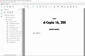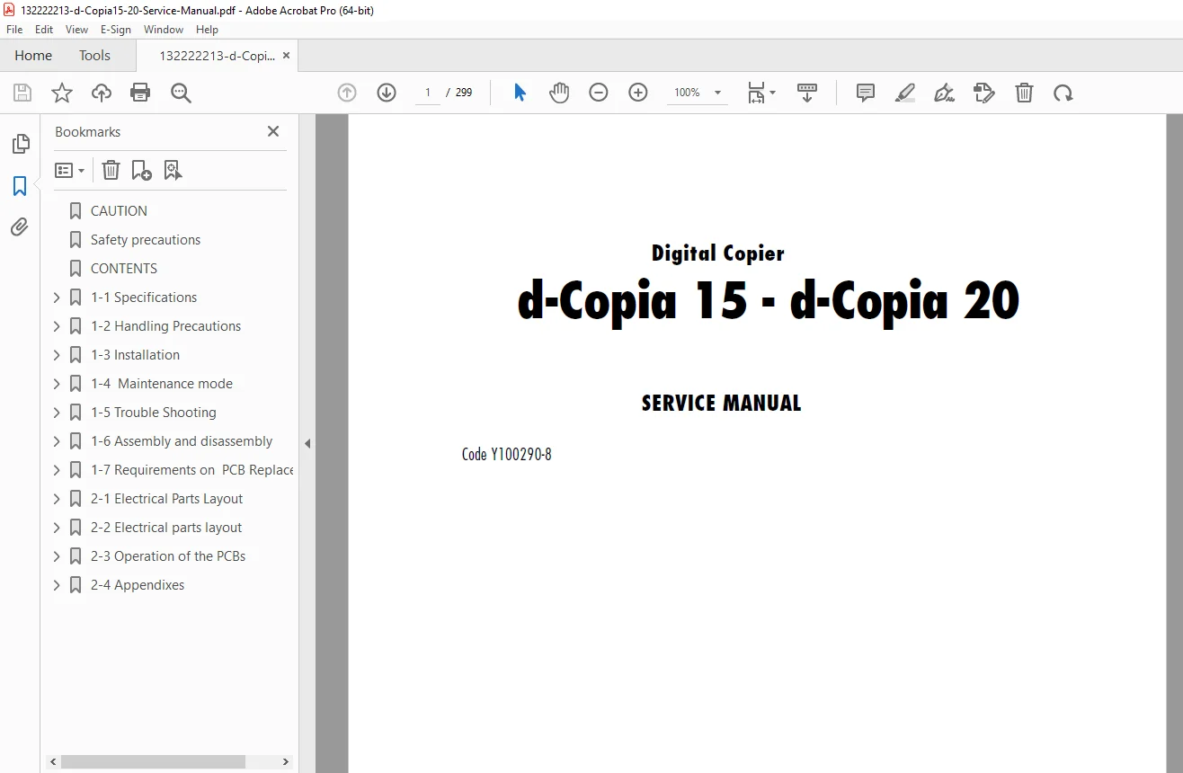
Olivetti d-Copia 15 & 20 Service Manual PDF DOWNLOAD
Original price was: $85.00.$18.95Current price is: $18.95.
Download the Olivetti d-Copia 15 service manual PDF for comprehensive d-Copia 20 copier troubleshooting guide, including Olivetti digital copier maintenance mode instructions and d-Copia self diagnostic codes explanation. This guide covers copier installation precautions Olivetti, paper misfeed detection, self-diagnosis, and image formation problems d-Copia copiers. Essential for technicians handling maintenance, assembly, disassembly, and electrical issues in these models.
Description
Olivetti d-Copia 15 & 20 Service Manual PDF DOWNLOAD
Description
This Olivetti d-Copia 15 service manual PDF download is a crucial resource for service technicians and repair professionals working on the d-Copia 15 and d-Copia 20 digital copiers. Revised in October 2009, it provides detailed coverage of specifications, handling precautions, installation, maintenance mode, troubleshooting, assembly and disassembly, mechanical construction, electrical parts, PCB operations, and appendixes to ensure safe and effective repairs. Key sections include a d-Copia 20 copier troubleshooting guide for issues like paper misfeeds, self-diagnostic codes, image formation problems d-Copia copiers such as white lines or blurring, and electrical problems like motor failures.
The manual emphasizes copier installation precautions Olivetti, including power supply warnings, grounding, ventilation, and handling high-voltage components to prevent fire or injury. It also details Olivetti digital copier maintenance mode instructions for executing items, setting defaults, and managing reports, alongside a thorough d-Copia self diagnostic codes explanation for errors from C000 to C9060.
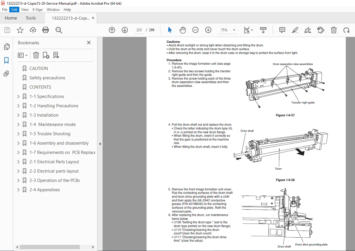
For assembly and disassembly, it offers step-by-step guidance on detaching components like paper feed pulleys, scanner wires, laser scanner units, chargers, drums, developers, transfer rollers, cleaning blades, and fixing units, with adjustments for registration, magnification, and margins.
No bookmarks or separate index are present, but the comprehensive contents section serves as a clear navigation guide, categorized below with bullet points for easy reference:
CONTENTS
- 1-1 Specifications
- 1-1-1 Specifications
- 1-1-2 Parts names and their functions
- (1) Copier
- (2) Operation panel
- 1-1-3 Machine cross section
- 1-1-4 Drive system
- (1) Drive system 1 (optical section)
- (2) Drive system 2 (drive motor drive train)
- 1-2 Handling Precautions
- 1-2-1 Drum
- 1-2-2 Developer and toner
- 1-2-3 Installation environment
- 1-3 Installation
- 1-3-1 Unpacking and installation
- (1) Installation procedure
- 1-3-2 Setting initial copy modes
- 1-3-3 Copier management
- (1) Using the copier management mode (15 cpm copier)
- (2) Setting department management items
- (3) Copy default
- (4) Using the copier management mode (20 cpm copier)
- (5) Setting department management items
- (6) Copy default
- (7) Machine default
- (8) Language
- 1-3-4 Installing the key counter (option)
- 1-3-5 Installing the original size detection sensor (option for the metric specifications of the 15 cpm copier only)
- 1-3-6 Installing the drawer heater (option)
- 1-3-1 Unpacking and installation
- 1-4 Maintenance Mode
- 1-4-1 Maintenance mode
- (1) Executing a maintenance item
- (2) Maintenance mode item list (for 20 cpm copier)
- (3) Contents of maintenance mode items (for 20 cpm copier)
- (4) Maintenance mode item list (for 15 cpm copier)
- (5) Contents of maintenance mode items (for 15 cpm copier)
- 1-4-1 Maintenance mode
- 1-5 Troubleshooting
- 1-5-1 Paper misfeed detection
- (1) Paper misfeed indication
- (2) Paper misfeed detection conditions
- (3) Paper misfeeds
- 1-5-2 Self-diagnosis
- (1) Self-diagnostic function
- (2) Self diagnostic codes
- 1-5-3 Image formation problems
- (1) No image appears (entirely white)
- (2) No image appears (entirely black)
- (3) Image is too light.
- (4) Background is visible.
- (5) A white line appears longitudinally.
- (6) A black line appears longitudinally.
- (7) A black line appears laterally.
- (8) One side of the copy image is darker than the other.
- (9) Black dots appear on the image.
- (10) Image is blurred.
- (11) The leading edge of the image is consistently misaligned with the original.
- (12) The leading edge of the image is sporadically misaligned with the original.
- (13) Paper creases.
- (14) Offset occurs.
- (15) Image is partly missing.
- (16) Fixing is poor.
- (17) Image is out of focus.
- (18) Image center does not align with the original center.
- (19) Image is not square.
- (20) Image contrast is low (carrier scattering).
- 1-5-4 Electrical problems
- (1) The machine does not operate when the main switch is turned on.
- (2) The drive motor does not operate (C200).
- (3) The scanner motor does not operate.
- (4) The toner feed motor does not operate.
- (5) Cooling fan motor 1 does not operate.
- (6) Cooling fan motor 2 does not operate.
- (7) Cooling fan motor 3 does not operate.
- (8) The drawer drive motor does not operate.
- (9) The registration clutch does not operate.
- (10) The upper paper feed clutch does not operate.
- (11) The lower paper feed clutch does not operate.
- (12) Paper feed clutch (ST)1 does not operate.
- (13) Paper feed clutch (ST)2 does not operate.
- (14) The bypass paper feed clutch does not operate.
- (15) The clearing lamp does not turn on.
- (16) The exposure lamp does not turn on.
- (17) The exposure lamp does not turn off.
- (18) The fixing heater does not turn on (C610).
- (19) The fixing heater does not turn off.
- (20) Main charging is not performed (C510).
- (21) Transfer charging is not performed.
- (22) No developing bias is output.
- (23) The original size is not detected.
- (24) The original size is not detected correctly.
- (25) The message requesting paper to be loaded is shown when paper is present in the upper drawer.
- (26) The message requesting paper to be loaded is shown when paper is present in the lower drawer.
- (27) The message requesting paper to be loaded is shown when paper is present on the bypass tray.
- (28) The size of paper in the upper drawer is not displayed correctly.
- (29) The size of paper in the lower drawer is not displayed correctly.
- (30) The printing width of the paper on the bypass tray is not detected correctly.
- (31) A paper jam in the paper feed, paper conveying or fixing section is indicated when the main switch is turned on.
- (32) The message requesting covers to be closed is displayed when the front cover, paper conveying unit and lower drawer left cover are closed.
- (33) Others.
- 1-5-5 Mechanical problems
- (1) No primary paper feed.
- (2) No secondary paper feed.
- (3) Skewed paper feed.
- (4) The scanner does not travel.
- (5) Multiple sheets of paper are fed at one time.
- (6) Paper jams.
- (7) Toner drops on the paper conveying path.
- (8) Abnormal noise is heard.
- 1-5-1 Paper misfeed detection
- 1-6 Assembly and Disassembly
- 1-6-1 Precautions for assembly and disassembly
- (1) Precautions
- (2) Running a maintenance item
- 1-6-2 Paper feed section
- (1) Detaching and refitting the upper and lower paper feed pulleys
- (2) Detaching and refitting the bypass paper feed pulley
- (3) Detaching and refitting the left registration cleaner assembly
- (4) Detaching and refitting the right registration cleaner assembly
- (5) Detaching and refitting the bypass paper width switch
- (6) Adjustment after roller and clutch replacement
- (6-1) Adjusting the leading edge registration of image printing
- (6-2) Adjusting the leading edge registration for memory image printing
- (6-3) Adjusting the center line of image printing
- (6-4) Adjusting the margins for printing
- (6-5) Adjusting the amount of slack in the paper
- 1-6-3 Optical section
- (1) Detaching and refitting the exposure lamp
- (2) Detaching and refitting the scanner wires
- (2-1) Detaching the scanner wires
- (2-2) Fitting the scanner wires
- (3) Detaching and refitting the laser scanner unit
- (4) Adjusting the skew and vertical shifting of the laser scanner unit
- (4-1) Adjusting the skew of the laser scanner unit
- (4-2) Adjusting the vertical shifting of the laser scanner unit
- (5) Detaching and refitting the ISU (reference)
- (6) Adjusting the position of the ISU (reference)
- (7) Adjusting the longitudinal squareness (reference)
- (8) Adjusting magnification of the scanner in the main scanning direction
- (9) Adjusting magnification of the scanner in the auxiliary scanning direction
- (10) Adjusting the scanner leading edge registration
- (11) Adjusting the scanner center line
- (12) Adjusting the margins for scanning an original on the contact glass
- 1-6-4 Main charging section
- (1) Detaching and refitting the charger assembly
- (2) Replacing the tungsten wire (reference)
- 1-6-5 Drum section
- (1) Detaching and refitting the drum
- 1-6-6 Developing section
- (1) Adjusting the position of the doctor blade (reference)
- 1-6-7 Transfer section
- (1) Detaching and refitting the transfer roller assembly
- 1-6-8 Cleaning section
- (1) Detaching and refitting the cleaning blade
- (2) Detaching and refitting the drum separation claw assemblies
- (3) Detaching and refitting the cleaning lower seal assembly
- 1-6-9 Fixing section
- (1) Detaching and refitting the fixing unit
- (2) Detaching and refitting the fixing unit thermistor
- (3) Detaching and refitting the heat roller separation claws
- (4) Detaching and refitting the fixing heater
- (5) Detaching and refitting the heat roller
- (6) Detaching and refitting the press roller
- 1-6-1 Precautions for assembly and disassembly
- 1-7 Requirements on PCB Replacement
- 1-7-1 Replacing the main PCB
- 1-7-2 Upgrading the firmware on the main PCB
- 1-7-3 Upgrading the firmware on the operation unit PCB (20 cpm copier only)
- 1-7-4 Adjustment-free variable resistors (VR)
- 2-1 Mechanical construction
- 2-1-1 Paper feed section
- 2-1-2 Main charging section
- 2-1-3 Optical section
- (1) Original scanning
- (2) Image printing
- 2-1-4 Developing section
- (1) Formation of magnetic brush
- (2) Toner density detection by the toner sensor
- (3) Toner density control
- (4) Correcting the toner sensor control voltage
- (5) Correcting toner output voltage
- 2-1-5 Transfer and separation section
- 2-1-6 Cleaning section
- 2-1-7 Charge erasing section
- 2-1-8 Fixing section
- 2-2 Electrical Parts Layout
- 2-2-1 Electrical parts layout
- (1) PCBs
- (2) Switches and sensors
- (3) Motors
- (4) Other electrical components
- 2-2-1 Electrical parts layout
- 2-3 Operation of the PCBs
- 2-3-1 Power source PCB
- 2-3-2 Main PCB
- 2-3-3 CCD PCB
- 2-3-4 Laser diode PCB
- 2-4 Appendixes
- Timing chart No. 1
- Timing chart No. 2
- Timing chart No. 3
- Timing chart No. 4
- Timing chart No. 5
- Timing chart No. 6
- Timing chart No. 7
- Timing chart No. 8
- Timing chart No. 9
- Timing chart No. 10
- Maintenance parts list
- Periodic maintenance procedures
- General connection diagram (1)
- General connection diagram (2)
Revision History (Formatted as a table for clarity):
| Revision | Date | Replaced pages | Remarks |
|---|---|---|---|
| 1 | August 31, 2009 | 1-2-11, 1-2-12, 1-2-14, 1-3-2, 1-3-4, 1-3-16, 1-3-48, 1-3-49, 1-5-2, 1-5-20 | – |
| 2 | October 22, 2009 | 2-4-1 to 2-4-4 | – |
This manual is vital for addressing image formation problems d-Copia copiers and following copier installation precautions Olivetti to maintain safety and performance. Equip yourself with this detailed Olivetti d-Copia 15 service manual PDF to tackle repairs confidently and efficiently—your go-to guide for keeping these reliable digital copiers running smoothly.
File Details
- Manual name: d-Copia 15 – d-Copia 20 Service Manual
- Models covered: d-Copia 15, d-Copia 20
- Year: 2009
- Manual PDF quality: High (clear text, diagrams, and formatting)
- No of pages: 299