OM H25 ENGINE FOR FORKLIFT TRUCKS XG 25 – XG 30 REPAIR MANUAL – PDF DOWNLOAD
$27.95
OM H25 ENGINE FOR FORKLIFT TRUCKS XG 25 – XG 30 REPAIR MANUAL – PDF DOWNLOAD
Description
OM H25 ENGINE FOR FORKLIFT TRUCKS XG 25 – XG 30 REPAIR MANUAL – PDF DOWNLOAD
FILE DETAILS:
OM H25 ENGINE FOR FORKLIFT TRUCKS XG 25 – XG 30 REPAIR MANUAL – PDF DOWNLOAD
Language : English
Pages :110
Downloadable : Yes
File Type : PDF
DESCRIPTION:
OM H25 ENGINE FOR FORKLIFT TRUCKS XG 25 – XG 30 REPAIR MANUAL – PDF DOWNLOAD
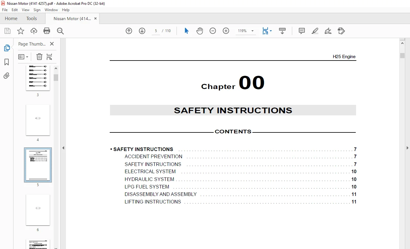
SAFETY INSTRUCTIONS
ACCIDENT PREVENTION
• The majority of mishaps or accidents in the shop occur due to the failure to observe the basic, simple safety
precautions and standards in place. Most accidents and their consequences can be avoided by exercising
the necessary caution and care.
• No matter how well a machine has been engineered or built, it is impossible to eliminate all causes of accidents.
• A careful and prudent mechanic can offer the best guarantee against mishaps.
• Keep all tools in perfect condition and use them correctly.
• Set aside an area in the shop to keep tools and disassembled parts and always keep them in this area
IMAGES PREVIEW OF THE MANUAL:
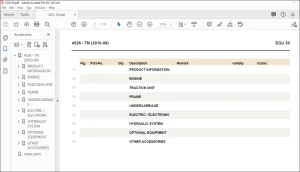
TABLE OF CONTENTS:
OM H25 ENGINE FOR FORKLIFT TRUCKS XG 25 – XG 30 REPAIR MANUAL – PDF DOWNLOAD
ACCIDENT PREVENTION 7
SAFETY INSTRUCTIONS 7
ELECTRICAL SYSTEM 10
HYDRAULIC SYSTEM 10
LPG FUEL SYSTEM 10
DISASSEMBLY AND ASSEMBLY 11
LIFTING INSTRUCTIONS 11
SPECIFICATIONS 15
OVERALL SPECIFICATIONS 15
INSPECTION AND ADJUSTMENT INFORMATION 15
• TUNING THE ENGINE 18
ADJUSTING THE IGNITION TIMING BY 12° 18
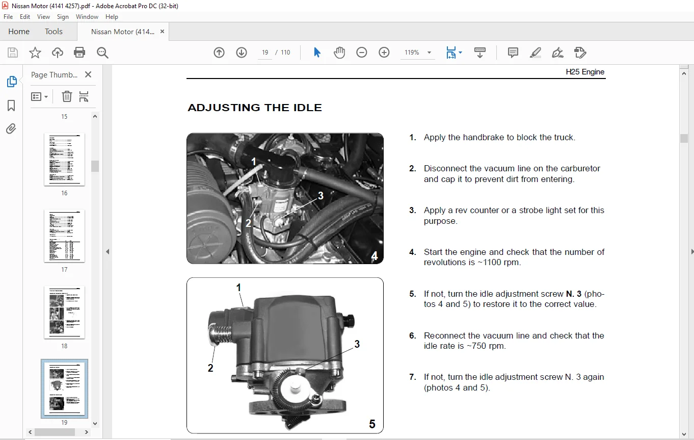
ADJUSTING THE IDLE 19
ADJUSTING THE CO VALUE 19 8
Cylinder arrangement 4 in line
Capacity cm3 2,472
Bore x stroke mm 92 0 x 93 0
Valve arrangement in head
Starting sequence 1-3-4-2
Number of segments 3
Compression segments 2
Scraper ring 1
Compression ratio 8 7
Minimum rated engine speed 650 rpm
INSPECTION AND ADJUSTMENT INFORMATION
Distribution
Valve clearance (when cold)
Intake mm 0,38
Exhaust mm 0,38
Valve head diameter
Intake mm 35,0 ÷ 35,2
Exhaust mm 30,0 ÷ 30,2
Valve length
Intake mm 108,55 ÷ 108,85
Exhaust mm 108,05 ÷ 108,35
Valve rod diameter
Intake mm 6,97 ÷ 6,985
Exhaust mm 6,945 ÷ 6,960
Length of expanded valve spring
Intake and exhaust mm 44,9
Lenght of compressed valve spring (valve open)
Intake and exhaust mm/N 29,3/385,4 ÷ 434,5
mm/kg 29,3/39,3 ÷ 44,3
Installed height of valve spring (valve closed)
Intake and exhaust mm/N 37,7/177,5 ÷ 201,0
mm/kg 37,7/18,1 ÷ 20,5
Valve spring out of square
intake and exhaust mm 1,5
Valve seat – guide clearance
Intake and exhaust mm 0,015 ÷ 0,048
Exhaust mm 0,040 ÷ 0,073
60424161 – 16 – 12/2003
H25 Engine
Distribution
Valve seat width
Intake mm 1,3 ÷ 1,5
Exhaust mm 1,6 ÷1,8
Valve seat angle
Intake and exhaust 45° degrees
Outer valve face angle
Intake and exhaust 45°30’ degrees
Camshaft
Camshaft flexure limit mm 0,05
Camshaft axial clearance mm 0,05 ÷ 0,23
Inside diameter of standard camshaft bushing
#1 front mm 45,472 ÷ 45,485
#2, #3 middle and rear mm 43,948 ÷ 43,961
Clearance between camshaft pin and bushing
#1, #3 front and rear mm 0,025 ÷ 0,051
#2 middle mm 0,038 ÷ 0,062
Camshaft lift
Intake and exhaust mm 36,750 ÷ 36,800
Engine shaft – bearings
Bearing pin diameter mm 62,942 ÷ 62,955
Maximum taper and roundness error mm 0,01
Wear limit mm 0,03
Assembly clearance mm 0,020 ÷ 0,062
Wear limit mm 0,1
Normal diameter of connecting rod pin mm 49,961 ÷ 49,974
Maximum taper and roudness error mm 0,01
Wear limit mm 0,03
Engine shaft axial clearance mm 0,05 ÷ 0,18
Wear limit mm 0,2
Maximum flexure of engine shaft less than 0,02 mm
Eccentricity / orthogonality of flywheel
On coupling side of converter less than 0,1 mm
Connecting rod
Wheel base mm 143,97 ÷ 144,03
Clearance between connecting rod / engine shaft pins mm 0,17 ÷ 0,3
Wear limit mm 0,4
Clearance between pin / connecting ron bearings mm 0,01 ÷ 0,066
Wear limit mm 0,03
Maximum flexure of connecting rod (for each 100 mm) less than 0,025 mm
60424161 – 17 – 12/2003
H25 Engine
Pistons
Piston diameter
Standard mm 91,965 ÷ 92,015
Increment 0,50 mm 92,465 ÷ 92,515
Increment 1,0 mm 92,965 ÷ 93,015
Clearance between segment / cavity
First ring mm 0,040 ÷ 0,073
Second and third rings mm 0,030 ÷ 0,063
Opening between segment ends
1° ring mm 0,25 ÷ 0,35
2° ring mm 0,15 ÷ 0,25
3° scraper ring mm 0,3 ÷ 0,9
Diameter of pin mm 20,993 ÷ 20,998
Clearance between pin / piston assemby mm 0,025 ÷ 0,045
Base plate
Inside diameter of cylinder hole mm 92,00 ÷ 92,05
Wear limit mm 0,2
Maximum taper and roundness error of cylinder hole mm 0,02
Surface flatness error less than 0,05 mm
Cylinder head
Questions? Email us: [email protected]
https://vimeo.com/856347913?share=copy
PLEASE NOTE:
- This is the SAME manual used by the dealers to troubleshoot any faults in your vehicle. This can be yours in 2 minutes after the payment is made.
- Contact us at [email protected] should you have any queries before your purchase or that you need any other service / repair / parts operators manual.
S.M