Service Manual for OM PIMESPO CTR 250 CPF 200 Electric Tractor PDF
$24.95
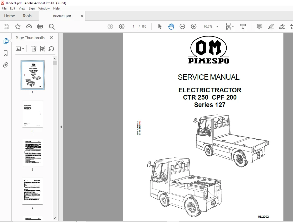
OM PIMESPO ELECTRIC TRACTOR CTR 250 CPF 200 Series 127 SERVICE MANUAL – PDF DOWNLOAD
Description
OM PIMESPO ELECTRIC TRACTOR CTR 250 CPF 200 Series 127 SERVICE MANUAL – PDF DOWNLOAD
FILE DETAILS:
OM PIMESPO ELECTRIC TRACTOR CTR 250 CPF 200 Series 127 SERVICE MANUAL – PDF DOWNLOAD
Language : English
Pages : 186
Downloadable : Yes
File Type : PDF
DESCRIPTION:
OM PIMESPO ELECTRIC TRACTOR CTR 250 CPF 200 Series 127 SERVICE MANUAL – PDF DOWNLOAD
INTRODUCTION
This is a guide to those responsible for the repair and maintenace of the 127 towtractor. A full inspection and maintenance procedure for up to 10000 hours, together with all necessary checks and adjustments can be found in the Operating Instructions publication 127 804 2531 E. The TABLE OF CONTENT gives the various sections into which this manual is divided. Due to the ever increasing higher standard of production methods, materials used, and the company policy of continuous improvement, various servicing procedures will have changed
IMAGES PREVIEW OF THE MANUAL:
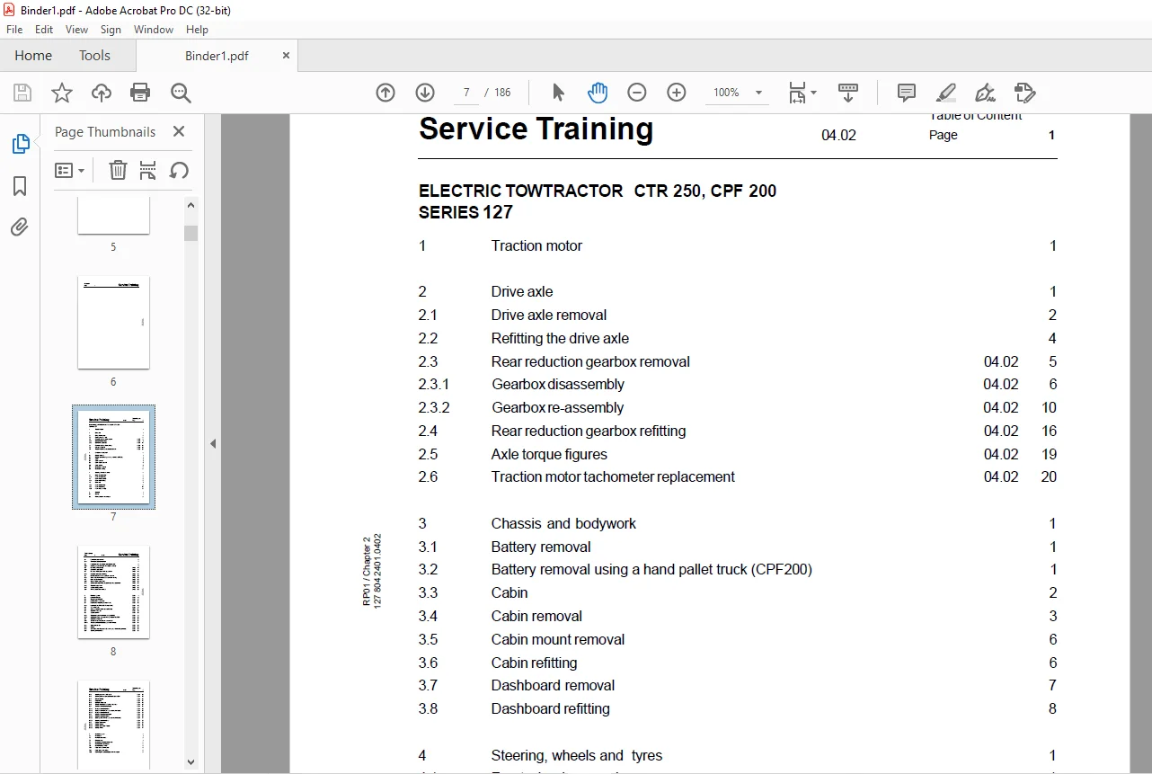
TABLE OF CONTENTS:
OM PIMESPO ELECTRIC TRACTOR CTR 250 CPF 200 Series 127 SERVICE MANUAL – PDF DOWNLOAD
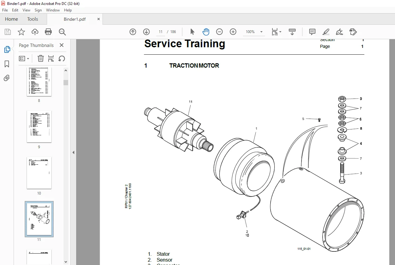
1 Traction motor 1
2 Drive axle 1
2.1 Drive axle removal 2
2.2 Refitting the drive axle 4
2.3 Rear reduction gearbox removal 04.02 5
2.3.1 Gearbox disassembly 04.02 6
2.3.2 Gearbox re-assembly 04.02 10
2.4 Rear reduction gearbox refitting 04.02 16
2.5 Axle torque figures 04.02 19
2.6 Traction motor tachometer replacement 04.02 20
3 Chassis and bodywork 1
3.1 Battery removal 1
3.2 Battery removal using a hand pallet truck (CPF200) 1
3.3 Cabin 2
3.4 Cabin removal 3
3.5 Cabin mount removal 6
3.6 Cabin refitting 6
3.7 Dashboard removal 7
3.8 Dashboard refitting 8
4 Steering, wheels and tyres 1
4.1 Front wheel removal 1
4.1.1 Front wheel refitting 1
4.2 Rear wheel removal 2
4.2.1 Rear wheel refitting 2
4.3 Front axle 3
4.3.1 Front axle removal 6
4.3.2 Front axle refitting 10
4.3.3 Front axle assembly 11
5 Controls 1
5.1 Brakes 1
5.3 Front disc brake examination 5
Service Training Table of Content
5.4 Front brake pad removal 6
5.4.1 Front brake pad replacement 7
5.5 Front brake disc and caliper assembly removal 8
5.5.1 Refitting of front brake disc and caliper assembly 9
5.6 Rear brake disassembly 04.02 10
5.6.1 Rear brake reassembly 04.02 11
5.7 Rear disc brake piston seals repacement 04.02 16
5.7.1 Rear disc brake piston refitting 04.02 18
5.8 Master cylinder and servo cylinder – removal 04.02 19
5.8.1 Brake master cylinder and servo cylinder – refitting 04.02 23
5.9 Brake system bleeding 04.02 23
5.10 Parking brake – adjustment 04.02 25
5.11 Inching cylinder pushrod and proximity switch adjustment 04.02 26
5.12 Footbrake adjustment 04.02 27
5.13 Accelerator adjustment 04.02 28
5.14 Parking brake cable removal 04.02 29
6 Electrical system 09.01 1
6.1 Control unit layout 09.01 12
6.2 Traction controller 1A1 09.01 13
6.3 Contactor 1K1a and 1K1b 09.01 14
6.4 Keyswitch S1 (Steering Power circuit) 09.01 15
6.4.1 Keyswitch S1 (TRACTION Power circuit) 09.01 16
6.5 Seat switch 1S1 09.01 17
6.6 Battery door lock switch 1S12 (CPF200) 09.01 18
6.7 Direction switch S11 09.01 19
6.8 Accelerator 1A4 09.01 20
6.8.1 Programming the Accelerator using LINDIAG 09.01 21
6.8.2 Programming the Accelerator using TRUCK DOCTOR 09.01 22
6.9 Footbrake switch 1S7 09.01 23
6.10 Traction motor Temperature sensor 1B12 09.01 24
6.10.1 Traction controller temperature sensor (internal) 09.01 24
6.11 Speed sensor 1B1 09.01 25
6.12 Inching 09.01 26
6.13 Axle brake proximity sensor 1B11 (on trucks with inching controls) 09.01 27
6.14 Steering controller 3A1 09.01 28
Table of Content
6.15 Steering pressure switch 1S22 09.01 29
6.16 Steering pump motor temperature sensor 3B11 09.01 29
6.17 Driver’s display 09.01 30
6.18 Diagnostics 09.01 48
6.19 LINDIAG menu map 09.01 49
6.20 TRUCK DOCTOR navigational structure 09.01 50
6.21 Traction controller parameters 09.01 51
6.21.1 Traction controller options 09.01 59
6.21.2 Traction controller test values (controller inputs) 09.01 60
6.21.3 Traction controller alarms 09.01 62
6.22 Steering controller parameters 09.01 65
6.22.1 Steering controller options 09.01 66
6.22.2 Steering controller test values (controller inputs) 09.01 67
6.22.3 Steering controller alarms 09.01 69
6.23 Display parameters 09.01 72
6.23.1 Display options 09.01 73
6.23.2 Display test values (inputs) 09.01 75
6.23.3 display alarms 09.01 77
7 Hydraulic system 1
7.1 Introduction 1
7.2 Hydraulic schematic 2
7.3 Filter renewal 4
7.4 Hydraulic tank breather renewal 4
7.5 Hydraulic fluid level check 4
7.6 Hydraulic pump motor 5
7.6.1 Pump and motor removal 6
7.6.2 Pump and motor refitting 8
7.6.3 Removing the hydraulic pump from the motor 8
10 Miscelaneous 1
10.1 AMP-SAAB connectors 1
10.2 Standard torques 2
10.3 Non standard torques 3
10.4 Special tools, sealants and compounds 04.02 4
10.5 Recommend lubricants 09.01 5
Questions? Email us: [email protected]
https://vimeo.com/858900874?share=copy
PLEASE NOTE:
- This is the same manual used by the dealers to diagnose and troubleshoot your vehicle
- You will be directed to the download page as soon as the purchase is completed. The whole payment and downloading process will take anywhere between 2-5 minutes
- Need any other service / repair / parts manual, please feel free to contact [email protected] . We still have 50,000 manuals unlisted
S.M