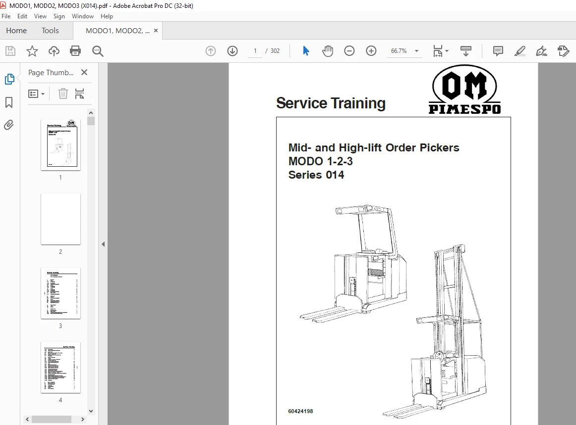
OM Pimespo Mid- and High-lift Order Pickers MODO 1-2-3 Series 014 Service Training Manual – PDF DOWNLOAD
$25.95
OM Pimespo Mid- and High-lift Order Pickers MODO 1-2-3 Series 014 Service Training Manual – PDF DOWNLOAD
Description
OM Pimespo Mid- and High-lift Order Pickers MODO 1-2-3 Series 014 Service Training Manual – PDF DOWNLOAD
FILE DETAILS:
OM Pimespo Mid- and High-lift Order Pickers MODO 1-2-3 Series 014 Service Training Manual – PDF DOWNLOAD
Language : English
Pages : 302
Downloadable : Yes
File Type : PDF
DESCRIPTION:
OM Pimespo Mid- and High-lift Order Pickers MODO 1-2-3 Series 014 Service Training Manual – PDF DOWNLOAD
Service Training
MEDIUM AND HIGH LIFT ORDER PICKER MODO
– Electromagnetic brake on the traction motor
– Electric reverse current brake for travel
– Safety two-handed operation in the aisle area
– Automatic lift-dependent travel speed reduction
– Battery discharge indicator with lift cutout
– Programmable braking and safety stops with operator platform raised
– Lateral safety barriers and safety switches starting from 1200 mm platform lift
– Overhead guard from 1800 mm platform lift
– Laterally removable battery
– Electric steering (Optional on MODO1 STD)
– Illuminated LCD display (except MODO1 STD)
– Steer wheel position indicator
– Working lights integrated on the overhead guard
– Inductive guidance
– Safety interlocks dependent on the facility
– Initial lift with centre open barrier
– Cabin ventilation
IMAGES PREVIEW OF THE MANUAL:
TABLE OF CONTENTS:
OM Pimespo Mid- and High-lift Order Pickers MODO 1-2-3 Series 014 Service Training Manual – PDF DOWNLOAD
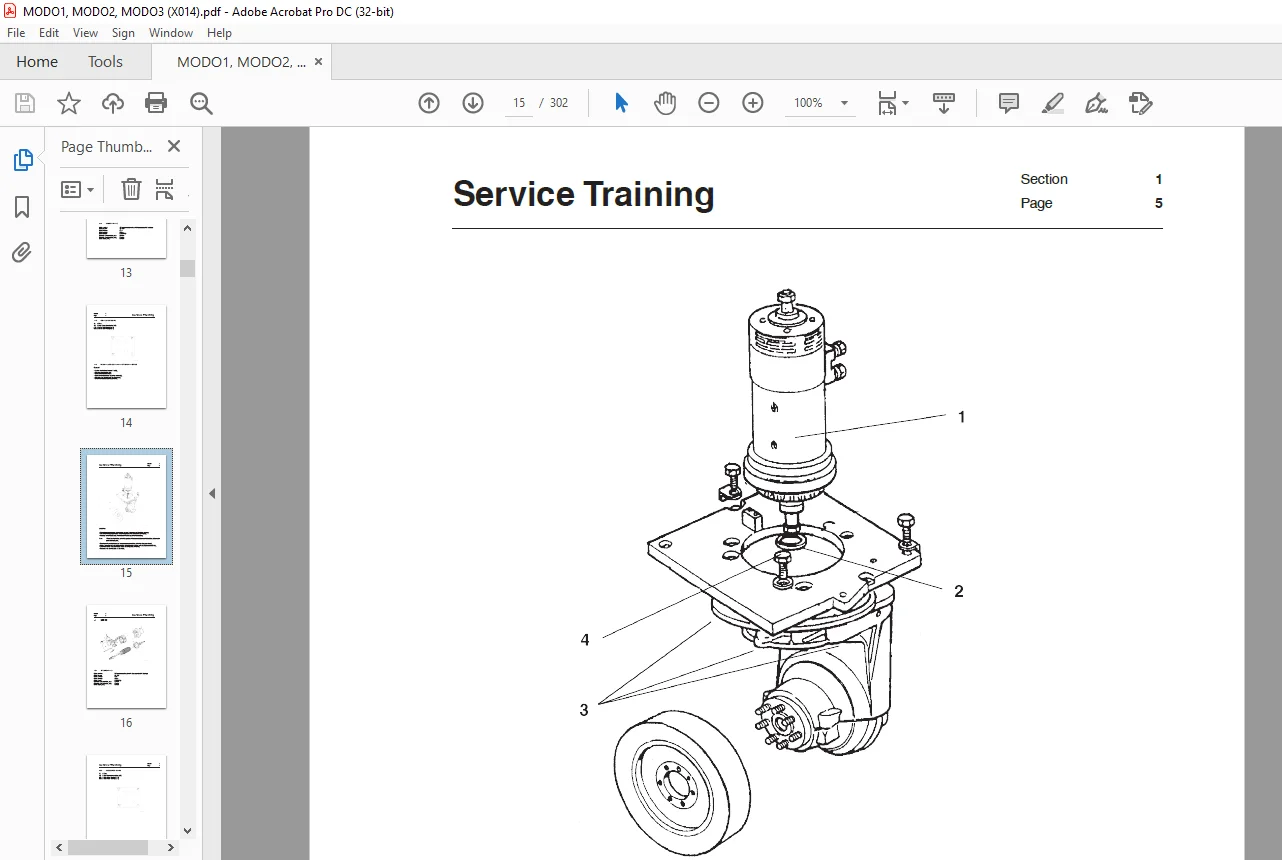
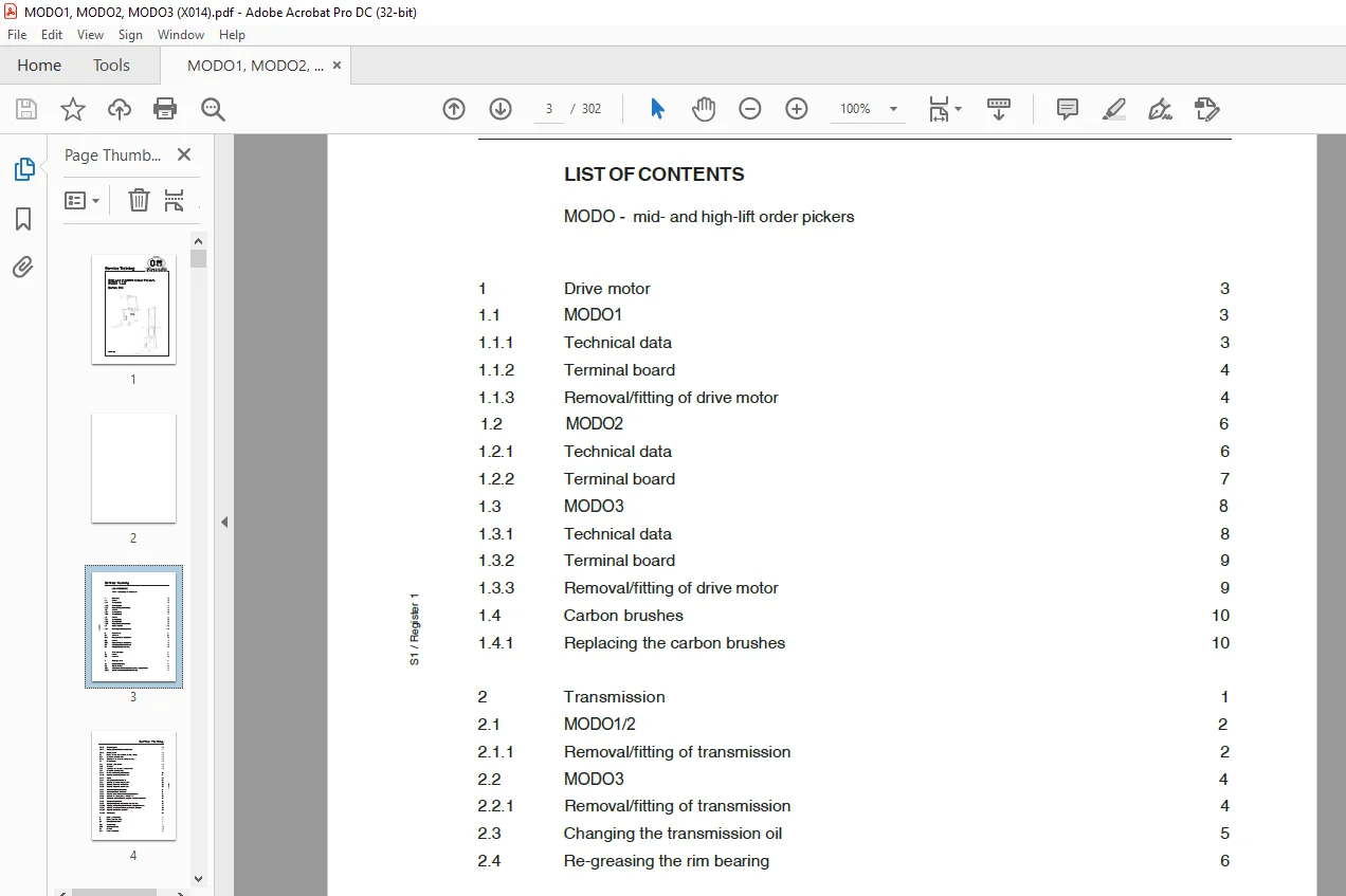
Drive motor 3
1.1 MODO1 3
1.1.1 Technical data 3
1.1.2 Terminal board 4
1.1.3 Removal/fitting of drive motor 4
1.2 MODO2 6
1.2.1 Technical data 6
1.2.2 Terminal board 7
1.3 MODO3 8
1.3.1 Technical data 8
1.3.2 Terminal board 9
1.3.3 Removal/fitting of drive motor 9
1.4 Carbon brushes 10
1.4.1 Replacing the carbon brushes 10
2 Transmission 1
2.1 MODO1/2 2
2.1.1 Removal/fitting of transmission 2
2.2 MODO3 4
2.2.1 Removal/fitting of transmission 4
2.3 Changing the transmission oil 5
2.4 Re-greasing the rim bearing 6
3 Trims and covers 1
3.1 MODO1 1
3.2 MODO2/3 2
4 Steering system 1
4.1 Mechanical steering 1
4.2 Electric steering 4
4.2.1 A description of the components and how to adjust them 7
4.2.1.1 Control circuit board (main circuit board) 7
Service Training
S1 / Register 1
4.2.1.2 Setpoint adjuster 10
4.2.1.3 Steering position indicator potentiometer 11
4.2.1.4 Steering motor 12
4.3 Electric steering with automatic steering centring 13
4.3.1 Description of components 13
4.3.1.1 Circuit board for automatic steering centring 13
4.4 Wire guidance 16
4.4.1 Structure of the system 16
4.4.2 Operation 18
4.4.3 Location of the components in the vehicle 19
4.4.4 Description of components
4.4.4.1 Position (actual value) potentiometer 20
4.4.4.2 Signal generator and guidance wire 21
4.4.4.3 Aerials 25
4.4.4.4 Wire guidance circuit board A9 28
4.4.5 Adjusting the wire guidance system 30
4.4.5.1 Checking the position of the aerials 30
4.4.5.2 Adjusting the position potentiometer 30
4.4.5.3 Calibrating the drive-side aerials 31
4.4.5.4 Calibrating the load-side aerials 31
4.4.5.5 Offsetting the position (actual value) potentiometer 31
4.4.5.6 Offsetting for steering errors – trimmer TM9 32
4.4.5.7 Setting the maximum steering range for corrective movements 33
4.4.5.8 Setting the amplification 33
4.4.5.9 Setting the weighting of the aerials when reversing 33
4.4.5.10 Adjusting maximum vehicle deviation from the guidance wire 34
4.4.5.11 Adjusting the maximum steering angle during locking on 35
4.4.5.12 Adjusting travel/braking recognition 35
4.4.5.12 Fault location 36
5 Brake system/controls 1
5.1 Electric generator brake 1
5.2 Magneto-electric brake 1
5.2.1 Technical data 1
5.2.2 Adjusting the brake 2
5.3 Controls 3
5.3.1 MODO1 brake lever 3
Service Training
S1 / Register 1
5.3.2 MODO2/3 control lever 5
6 Electrical system 1
6.1 MODO1-STD electrical systems 3
6.1.1 Block circuit diagram 3
6.1.2 Digital control A1 4
6.1.2.1 Power unit MODO 7
6.1.2.2 Current path -forward travel direction 8
6.1.2.3 Current path -reverse travel direction 9
6.1.3 Diagnostic instrument 11
6.1.3.1 Programming 12
6.1.3.1.1 Program function menu 14
6.1.3.1.2 Tester function menu 16
6.1.3.1.3 Save parameter function menu 18
6.1.3.1.4 Restore parameter function menu 19
6.1.3.1.5 Alarm function menu 20
6.1.3.1.6 Program VACC function menu 23
6.1.4 Component descriptions for MODO1-STD 25
6.1.4.1 Drive and lift control system 25
6.1.4.2 Display (6P1) 27
6.1.4.3 Battery discharge indicator and operating time indicator 29
6.1.4.4 Cabin circuit board A5 30
6.1.4.5 Interface circuit board A6 37
6.1.4.6 Connection circuit board A4, Electric steering 41
6.1.4.7 Mast circuit board A4 for MODO1-STD 44
6.2 Electrical systems, MODO1-LX, MODO2, MODO3 47
6.2.1 Block circuit diagram 47
6.2.2 Drive and pump control system 48
6.2.3 Display and truck programming 50
6.2.3.1 Direction of travel and cabin movement indicator 50
6.2.3.2 Steering lock indicator 50
6.2.3.3 Speed indicator 51
6.2.3.4 Aisle and sensor recognition indicator 52
6.2.3.5 Battery status indicator 53
6.2.3.6 Operating time and programming mode activation indicator 53
6.2.3.7 Cabin height indicator 54
6.2.3.8 Use of masterkey (programming operation) 57
Service Training
S1 / Register 1
6.2.3.9 Control display 58
6.2.3.10 Parameter setting 63
6.2.3.11 Description of the variable parameters 64
6.2.3.12 Checking input signals on the cabin circuit board 67
6.2.3.13 Display of current & voltage values of the drive and pump control system 69
6.2.3.14 Setting the wheel setting indicators on the display 70
6.2.3.15 Last five alarm messages – display and deletion 72
6.2.3.16 Truck configuration setting 74
6.2.3.17 Lift stop programming 75
6.2.3.18 Offset setting of setpoint transmitters 77
6.2.3.19 Setting display contrast 78
6.2.4 Description of components for MODO1-LX, MODO2, MODO3 79
5.2.4.1 Drive control and lift control 79
6.2.4.2 Display (Master) 6P1 81
6.2.4.3 A5 cabin circuit board 84
6.2.4.4 A2 interface circuit board 90
6.2.4.5 A6 locking circuit board 97
6.2.4.6 A4 mast circuit board for MODO1-LX, MODO2/3 Triplex 101
6.2.4.7 A4 mast circuit board for MODO2/3 Duplex 104
6.2.4.8 A10 power supply circuit board (only on MODO3) 106
6.3 Circuit diagrams 108
6.3.1 Circuit diagram MODO1-STD 108
6.3.2 Circuit diagram MODO1-LX 110
6.3.3 Circuit diagram MODO2/ MODO3 112
7 Hydraulic systems 1
7.1 MODO1 hydraulic system 1
7.1.1 Hydraulic unit 1
7.1.2 Pump motor 2
7.1.2.1 MODO1 duplex mast pump motor 2
7.1.2.2 MODO1 triplex mast pump motor 3
7.1.3 Pump unit 4
7.1.3.1 Cleaning the pressure filter 5
7.1.3.2 Cleaning the suction and return sieves 5
7.1.3.3 Adjusting the pressure control valve 6
7.1.3.4 Changing the hydraulic oil 7
7.2 MODO2/3 hydraulic system 8
Service Training
S1 / Register 1
7.2.1 Changing the hydraulic oil filter 9
7.2.2 Changing the hydraulic oil 9
7.2.3 MODO2 pump motor 10
7.2.4 MODO3 pump motor 11
7.3 Valve control function table 12
7.3.1 MODO1 02-STD – Type C valve block 12
7.3.2 MODO1-LX, MODO2/3 – Type A or B valve block
7.4 Valve block 13
7.4.1 Type A valve block without initial lift 14
7.4.2 Type A valve block with initial lift 15
7.4.3 Type B valve block without initial lift 16
7.4.4 Type B valve block with initial lift 17
7.4.5 Type C valve block 18
7.5 Hydraulic circuit diagrams 20
7.5.1 MODO1 01-STD hydraulic circuit diagram 20
7.5.2 MODO1 01-LX hydraulic circuit diagram 22
7.5.3 MODO1 02-STD hydraulic circuit diagram 24
7.5.4 MODO1 02-LX hydraulic circuit diagram 26
7.5.5 MODO2/3 01 hydraulic circuit diagram 28
7.5.6 MODO2/3 02 hydraulic circuit diagram 30
7.6 Pressure settings 32
9 Interlock systems MODO 1
9.1 Introduction 1
9.2 General description of safety functions 2
9.2.1 Assignment of speeds 2
9.2.2 Assignment of sensors and reflectors 2
9.2.3 Aisle detection 3
9.2.4 Aisle detection through reset + set sensor 3
9.2.5 Continuous aisle detection 3
9.2.6 Creep speed 4
9.2.7 Speed monitoring 4
9.2.8 Stop 4
9.2.8.1 Time top (UPA) 4
9.2.8.2 Continuous stop 4
9.2.9 Zone detection (UPA) 5
9.2.9.1 Zone detection with reduced roof height 5
Service Training
S1 / Register 1
9.2.9.2 Zone detection for intersections with personnel or vehicle traffic 6
9.3 Function code 7
9.4 Sensor types 10
9.4.1 Optical sensors 10
9.4.1.1 Adjustment and monitoring 11
9.4.1.2 Electrical connection 11
9.4.1.3 Reflectors 11
9.4.2 Inductive sensors (UPA) 12
9.4.3 Magnetic sensors (UPA) 12
9.4.4 Assignment of sensors 13
9.4.5 Designation of sensors 13
9.4.6 Sensor connections on vehicle 14
9.5 Interlock versions 19
9.5.1 Aisle detection 21
9.5.1.1 Aisle detection through set + reset function 21
9.5.1.1.1 1 open aisle end 21
9.5.1.1.2 2 open aisle ends 22
9.5.1.2 Aisle detection through continuous sensing 23
9.5.1.2.1 1 open aisle end 23
9.5.1.2.2 2 open aisle ends 24
9.5.2 Speed reduction 25
9.5.2.1 1 open aisle end: creep speed and speed monitoring at closed end 25
9.5.2.2 1 open aisle end: creep speed and speed monitoring at both ends 26
9.5.3 Speed reduction with stop 27
9.5.3.1 1 open aisle end: creep speed with speed monitoring and stop at closed end 27
9.5.3.2 1 open aisle end: creep speed with speed monitoring and stop at both ends 28
9.5.3.3 1 open aisle end: creep speed with speed monitoring and continuous stop at closed end
and creep speed with speed monitoring and time stop (UPA) at open end 29
9.5.3.4 2 open aisle ends: creep speed with speed monitoring and stop at both ends 30
9.5.4 Zone detection HEIGHT1 or BLOCK3 (UPA) 31
9.5.4.1 Zone detection for areas with lower roof height (lower zones) 31
9.5.4.1.1 Detection of lower zones with individual signal encoders in aisle area 31
9.5.4.1.2 Detection of lower zones with continuous signal encoders in aisle area 32
9.5.4.1.3 Detection of lower zones in free travel 33
9.5.4.2 Zone detection for intersections with personnel or vehicle traffic 34
9.6 Positioning of sensors and signal encoders 35
9.6.1 Aisle detection through individual signal encoders with set and reset function 36
Service Training
S1 / Register 1
9.6.2 Aisle detection through continuous signal encoder 40
9.6.3 Creep speed with speed monitoring at aisle end 44
9.6.3 1 Installation of optical signal encoders on shelf cross beam 44
9.6.3.2 Installation of optical signal encoders on shelf columns 45
9.6.4 Creep speed with speed monitoring and stop at aisle end 49
9.6.4.1 Installation of optical signal encoders on shelf cross beam 49
9.6.4.2 Installation of optical signal encoders on shelf cross beam and columns 50
9.6.4.3 Installation of optical signal encoders on shelf columns only 51
9.6.4.4 Installation of inductive or magnetic signal encoders for MODO1, MODO2 52
9.6.4.5 Installation of inductive or magnetic signal encoders for MODO3 53
9.6.5 Zone detection for reduced roof height (UPA) 57
9.6.5.1 For zones within the aisle area 57
9.6.5.1.1 Detection through individual signal encoders 57
9.6.5.1.2 Detection through continuous signal encoders 61
9.6.5.2 For zones outside the aisle area 62
9.6.6 Zone detection for aisle intersections (UPA) 66
9.6.6.1 Detection through individual signal encoders 66
9.6.6.2 Detection through continuous signal encoders 67
9.7 Application example 68
Need help? Contact: [email protected]
https://vimeo.com/856350731?share=copy
PLEASE NOTE:
- This is the SAME manual used by the dealers to troubleshoot any faults in your vehicle. This can be yours in 2 minutes after the payment is made.
- Contact us at [email protected] should you have any queries before your purchase or that you need any other service / repair / parts operators manual.
S.M