OM Pimespo Series 4032XE 13 3ac, XE 15 3ac, XE 15ac,XE 16 3ac, XE 16ac, XE 18 3ac, XE 1 Bac, XE20 3ac, XE20ac Workshop Manual – PDF
$27.95
OM Pimespo Series 4032XE 13 3ac, XE 15 3ac, XE 15ac,XE 16 3ac, XE 16ac, XE 18 3ac, XE 1 Bac, XE20 3ac, XE20ac Workshop Manual – PDF DOWNLOAD
Description
OM Pimespo Series 4032XE 13 3ac, XE 15 3ac, XE 15ac,XE 16 3ac, XE 16ac, XE 18 3ac, XE 1 Bac, XE20 3ac, XE20ac Workshop Manual – PDF DOWNLOAD
FILE DETAILS:
OM Pimespo Series 4032XE 13 3ac, XE 15 3ac, XE 15ac,XE 16 3ac, XE 16ac, XE 18 3ac, XE 1 Bac, XE20 3ac, XE20ac Workshop Manual – PDF DOWNLOAD
Language : English
Pages : 386
Downloadable : Yes
File Type : PDF
DESCRIPTION:
OM Pimespo Series 4032XE 13 3ac, XE 15 3ac, XE 15ac,XE 16 3ac, XE 16ac, XE 18 3ac, XE 1 Bac, XE20 3ac, XE20ac Workshop Manual – PDF DOWNLOAD
Product information
Instruction and maintenance manual
This chapter gives information taken from the instruction and maintenance manual, considered as of interest for the assistance technician
General Forklift Description
- The model described in this manual is an electric forklift with seated operator and counterbalanced forks.
- This model can be equipped with the following main equipment:
? side shifts
? positioners
? grippers with jaws or forks
? tipping
? load arms
TABLE OF CONTENTS:
OM Pimespo Series 4032XE 13 3ac, XE 15 3ac, XE 15ac,XE 16 3ac, XE 16ac, XE 18 3ac, XE 1 Bac, XE20 3ac, XE20ac Workshop Manual – PDF DOWNLOAD
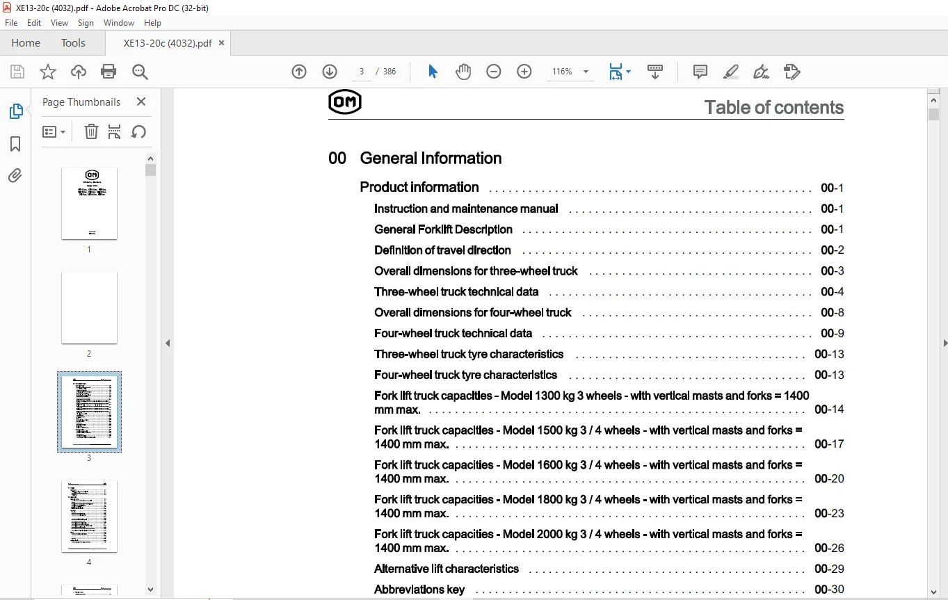
00 General Information
Product information
Instruction and maintenance manual
General Forklift Description
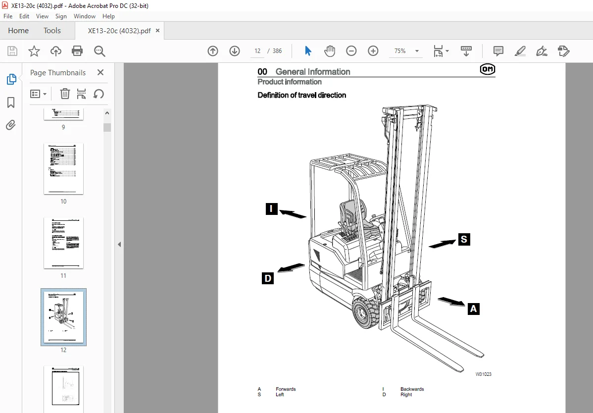
Definition of travel direction
Overall dimensions for three-wheel truck
Three-wheel truck technical data
Overall dimensions for four-wheel truck
Four-wheel truck technical data
Three-wheel truck tyre characteristics
Four-wheel truck tyre characteristics 00
Fork lift truck capacities – Model 1300 kg 3 wheels – with vertical masts and forks = 1400
mmmax. 00
Fork lift truck capacities – Model 1500 kg 3 / 4 wheels – with vertical masts and forks =
1400 mm max. 00
Fork lift truck capacities – Model 1600 kg 3 / 4 wheels – with vertical masts and forks =
1400 mm max. 00
Fork lift truck capacities – Model 1800 kg 3 / 4 wheels – with vertical masts and forks =
1400 mm max. 00
Fork lift truck capacities – Model 2000 kg 3 / 4 wheels – with vertical masts and forks =
1400 mm max. 00
Alternative lift characteristics 00
Abbreviations key 00
Tyre inflation pressure 00
Lamps 00
Battery dimensions and weights 00
Internal accessibility 00
Safety features 00
Transporting the Forklift 00
Forklift towing 00
Loading and unloading the truck 00
Safety precautions oo
Description of safety symbols 00
Operations Preliminary to Maintenance 00
To avoid accidents 00
General safety Regulations 00
Safety Regulations Relative to Operating Materials 00
Table of contents
01 Service
Maintenance
Preliminary operations before commissioning
Synoptic Table of Maintenance Operations
Supply Table
02 Diagnostics
Diagnostic software
Connection between the diagnostics PC and the forklift
Software
Description of the menus in the WINPCCONSOLE software
Description of the PARAMETER menu
Description of the TESTER menu
TESTER/ Diagnostics Function
Parameters
Introduction
Parameters of the DUAL AC module
Parameters of the AC2 FLASH module
Parameters of the ECO DISPLAY module
Parameterisation of the drive function
Parameterisation of the steering function
Parameterisation of the electric braking function
Parameterisation of the battery state monitoring function
Parameterisation of the lifting function
Parameterisation of the hydraulically assisted steering function
Parameterisation of the tilt, side shift (SLI) and 4 th lever functions
Alarms
State of the truck during an alarm situation
Alarms list
Analogue signals
Summary of signals from the analogue transducers
Workshop literature ? 40328042303 EN ? 05/2008 III
11 Traction motor
Asynchronous motors
Features of the asynchronous motors
Checking the asynchronous motors
Front axle motors
Traction motor technical data
Traction
Traction motor
Drive motor checks
Drive motor decomposition
Encoder
Replacing the traction encoder
Electrical connections of the traction motors
Temperature sensor KTY84
Insulation testing of traction motor
22 Gearbox
Front axle
Front axle technical data
Removal of front axle with traction motors
Front axle reassembly
Reducer gearbox
Front axle reducer gearbox topography
Front axle reduction gear disassembly/reassembly
Removal/ reassembly of the drive wheel reducer gearbox
Check reducer gearbox oil level
Reducer gearbox oil change
31 Truck
Counterweight
Counterweight removal
Counterweight reassembly
Covers
Cover topography
Side covers removal / reassembly
Battery cover removal/ reassembly
Step plate removal / reassembly
IV Workshop literature ? 40328042303 EN ? 05/2008
Table of contents
Distributor cover removal/ reassembly 31
Batteries 31
Battery removal 31
34 Driver’s seat
Overhead guard 34
Removal of the overhead guard 34
Reassembly of the overhead guard 34
Fairings 34
Removal/ reassembly of the steering column panelling 34
Removal / reassembly of the control panel panelling 34
42 Steering system
Steering distributor 42
Steering distributor technical data 42
Removal/ reassembly of the steering distributor 42
Steering distributor pressure switch technical data 42
Replacing the steering distributor pressure switch 42
Steering column 42
Removal / reassembly of the steering column 42
Steering axle 42
Three-wheel truck rear axle technical data 42
Three-wheel truck axle removal 42
Three-wheel truck axle reassembly 42
Three-wheel axle disassembly 42
Three-wheel truck potentiometer technical data 42
Replacement of the three-wheel steering axle potentiometer 42
Four-wheel truck axle technical data 42
Four-wheel axle removal 42
Four-wheel truck axle reassembly 42
Four-wheel axle disassembly 42
Four-wheel truck potentiometer technical data 42
Replacing the four-wheel truck potentiometer 42
Lubricating the steering axle 42
46 Wheels and tyres
General information 46
Safety regulations for wheels and rims 46
Workshop literature ? 40328042303 EN ? 05/2008 V
Table of contents
General information for changing tyres 46
Tyrewear check 46
Wheel change 46
Wheel change 46
Wheel decomposition 46
Disassembly/assembly of tyres on rims with movable flange 46
Quick tyres assembly/disassembly 46
Tightening torques 46
Check wheel nut tightness (every 10 hours during run-in) 46
49 Braking system
Parking brake 49
Removal / reassembly of the parking brake lever 49
Parking brake control cable replacement 49
Replacing the parking brake microswitch 49
Parking brake adjustment 49
Service brake 49
Service brake pedal removal 49
Service brake pedal reassembly 49
Stop lights microswitch replacement 49
Replacing the service brake pedal potentiometer 49
Braking group 49
Removing / installing the brake group 49
50 Controls
Accelerator pedal 50
Accelerator pedal 50
Accelerator pedal potentiometer 50
56 Display elements
Display 56
Plate data 56
Connector 56
Multifunction panel 56
Setting the date and time 56
Speed reductions 56
Functionality of the display buttons 56
VI Workshop literature ? 40328042303 EN ? 05/2008
Table of contents
Data modification pushbutton functions 56
Multifunction panel removal/ reassembly 56
Alarms 56
60 Electronic system
Software versions 60
Reference software versions 60
Electronic traction system 60
Characteristics of the electronic drive system 60
Plate data: traction 60
Connectors 60
Closing the general contactor 60
Thermal sensor operation 60
Hydraulic functions electronic system 60
Functions of the AC2 module 60
Plate data: pump 60
AC2 Connectors 60
Control of the general contactor 60
Lowering solenoid valve operation 60
Thermal sensor operation 60
Types of hours counters 60
Types of hour counters: 60
Hours counter management in case of electronic system replacement 60
Resetting the machine hours 60
Electrical system components 60
Electronics panel technical data 60
Electronics panel removal/ reassembly 60
Protection of the electrical system 60
Emergency pushbutton 60
Replacing the emergency stop button 60
Assembly/ disassembly of the lights switch (option) 60
Lamp replacement (if applicable) 60
Work light replacement procedure (optional) 60
Contactors 60
Location of Fuses 60
Changing a fuse 60
Workshop literature ? 40328042303 EN ? 05/2008 VII
Table of contents
Buzzer 60
Fans 60
Encoder description 60
71 Hydraulic components
Hydraulic circuit 71
Layout of hydraulic parts 71
Hydraulic system assembly diagram 71
Pump motor 71
Pump motor technical data 71
Pump motor removal 71
Pump motor reassembly 71
Replacing the pump 71
Replacing the pump motor encoder 71
Replacing the pump motor temperature sensor 71
Oil tank 71
Hydraulic oil tank 71
Oil tank removal/ reassembly 71
Check hydraulic tank oil level 71
Hydraulic distributor 71
Hydraulic distributor technical data 71
Hydraulic distributor removal/ reassembly 71
Replacing the hydraulic distributor probe 71
Valves 71
Safety valve (load lowering block) (VBDC) 71
Safety valve layout 71
Tilt cylinders 71
Tilt cylinders 71
Tilt cylinder removal / reassembly 71
Air bleeding of the tilt cylinders 71
80 Lifts
Lifts 80
Technical data for service 80
Lift typologies 80
Simplex Lift 80
Duplex Lift 80
VIII Workshop literature ? 40328042303 EN ? 05/2008
Table of contents
Triplex Lift
Load chain locking device
Fork carriage retaining device
Assembly of the mast/ carriage support rollers
Check
Disassembly of the Simplex lift cylinder
Disassembly of the side cylinders of the Duplex lift
Disassembly of the side cylinders of the Triplex lift
Duplex/ Triplex central cylinder
Limit stop dampers
Disassembly of the fork carriage
Tilt cylinder
Lift disconnection
Lift reassembly
Air bleeding of the lift cylinders
Lift cylinders
Annex
A Diagrams
Wiring diagrams
Electrical circuit diagram 40328020002
Electrical connection diagram 40328020001
Hydraulic diagrams
Hydraulic diagram 40328082502
IMAGES PREVIEW OF THE MANUAL:
Customer Support: [email protected]
https://vimeo.com/858155079?share=copy
PLEASE NOTE:
- This is the SAME manual used by the dealers to troubleshoot any faults in your vehicle. This can be yours in 2 minutes after the payment is made.
- Contact us at [email protected] should you have any queries before your purchase or that you need any other service / repair / parts operators manual.
S.M