OM Series 115-12 Tough terrain XRS148 c, XRS168 c, XRS208c Workshop Manual – PDF DOWNLOAD
$26.95
OM Series 115-12 Tough terrain XRS148 c, XRS168 c, XRS208c Workshop Manual – PDF DOWNLOAD
Description
OM Series 115-12 Tough terrain XRS148 c, XRS168 c, XRS208c Workshop Manual – PDF DOWNLOAD
FILE DETAILS:
OM Series 115-12 Tough terrain XRS148 c, XRS168 c, XRS208c Workshop Manual – PDF DOWNLOAD
Language : English
Pages : 224
Downloadable : Yes
File Type : PDF
DESCRIPTION:
OM Series 115-12 Tough terrain XRS148 c, XRS168 c, XRS208c Workshop Manual – PDF DOWNLOAD
Introduction
This is a guide to those responsible for the repair and maintenance of the 115-03 reach truck. A full inspection and maintenance procedure for up to 10000 hours, together with all necessary checks and adjustments can be found in the User Manual. Due to the ever increasing higher standard of production methods, materials used, and the company policy of continuous improvement, some servicing procedures detailed in this manual may have changed. We are therefore unable to consider any claims based on the specication, illustrations and descriptions contained in this manual.
IMAGES PREVIEW OF THE MANUAL:
TABLE OF CONTENTS:
OM Series 115-12 Tough terrain XRS148 c, XRS168 c, XRS208c Workshop Manual – PDF DOWNLOAD
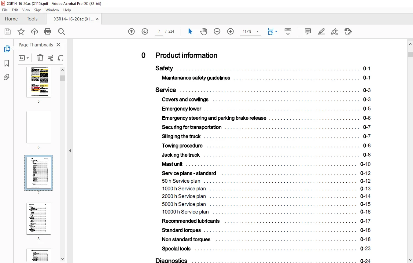
Product information
Safety 0
Maintenance safety guidelines 0
Service 0
Covers and cowlings 0
Emergency lower 0
Emergency steering and parking brake release 0
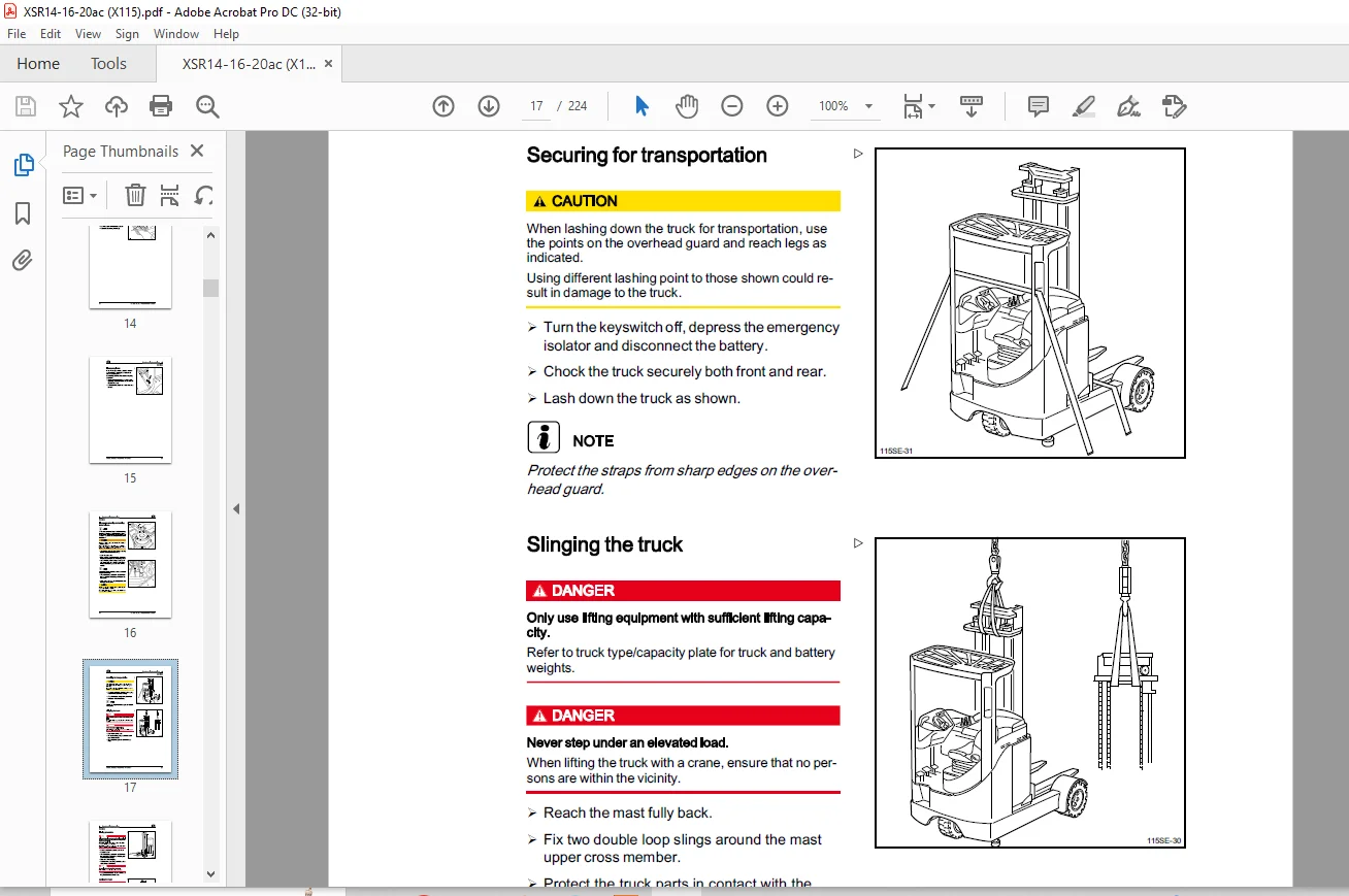
Securing for transportation 0
Slinging the truck 0
Towing procedure 0
Jacking the truck 0
Mast unit 0
Service plans – standard 0
Recommended lubricants 0
Standard torques 0
Non standard torques 0
Special tools 0
Diagnostics 0
Overview 0
Canbox 0
Software update for Can box 0
Diagnostic software 0
Traction diagnostic codes 0
Hydraulic diagnostic codes 0
Steering diagnostic codes 0
Display diagnostic codes 0
LAC – Traction diagnostic codes 0
LAC – Hydraulic diagnostic codes 0
1 Motor
Traction motor 1
Traction motor 1
VI Workshop literature ? 115 801 21 05 EN ? 01/2010
Table of contents (§)
2 Axles
Mechanical drive axle 2
Drive wheel 2
Rubber suspension spring 2
3 Chassis, bodywork and fittings
Chassis 3
Bump stop adjustment 3
Covers and panelling 3
Steering binnacle 3
Operator’s console 3
Operator’s seat 3
Seat assembly 3
Battery carrier 3
Battery carrier 3
4 Undercarriage
Electrical steering 4
Steering wheel potentiometer 4
Drive wheel position potentiometer 4
Steering motor 4
Wheels and tyres 4
Load wheels 4
Brake installation 4
Traction motor brake (standard) 4
Load wheel brakes 4
5 Controls
Drive and brake controls 5
Accelerator and brake pedals 5
Operating elements 5
Joysticks 5
6 Electric/electronic
Battery and accessories 6
The battery 6
Battery lock sensor 6
Electrical control
Safety precautions
EMC – Electromagnetic compatibility
AC Control – operating principle
Connector locations
Fuses
Emergency isolator
13 Volt power supply
Control module (LDC 61) -A2
ConnectorX13
Charge resistor module -A 11
Electrical control – Traction
Traction power module
Direction selection switch
Parking brake
Accelerator
Brake pedal switch
Regenerative braking
Traction motor temperature sensor
Switch controlled speed reduction and 8.5 m switch
Curve control
Electrical control – Hydraulics
Hydraulic power module
Valve voltage supply
Joysticks
Joystick voltage supply
Joystick operation
Hydraulic pump motor temperature sensor
Lower lock valve
Lift and lower – electrical operation
Reach – electrical operation
Sideshift – electrical operation
Tilt – electrical operation
Lift stop sensor
Reach system
Electrical control – Steering
Steering system overview
Drive wheel position potentiometer
Table of contents
Table of contents
Steering wheel unit
Electrical control – Display
Operator’s display
7 Hydraulic installation
Operating hydraulics
Change the hydraulic oil and suction filter
Hydraulic motor and pump assembly
Valve block
Hydraulic valve block
8 Load lift system
Mast unit
Mast
Cylinders
Reach cylinder
Tilt cylinders
Load support
Sideshift unit
Forks
Annex
10 Circuit Diagrams
Electric diagrams
Circuit diagram (Standard) 115 802 60 14
Circuit diagram (Variable electric brake) 115 802 60 09
Hydraulic diagrams
Hydraulic circuit
Customer Support: [email protected]
https://vimeo.com/856715047?share=copy
PLEASE NOTE:
- This is the same manual used by the dealers to diagnose and troubleshoot your vehicle
- You will be directed to the download page as soon as the purchase is completed. The whole payment and downloading process will take anywhere between 2-5 minutes
- Need any other service / repair / parts manual, please feel free to contact [email protected] . We still have 50,000 manuals unlisted
S.M