Panasonic CF-1000 Laptop Computer Service Manual – PDF DOWNLOAD
Original price was: $80.00.$18.95Current price is: $18.95.
Panasonic CF-1000 Laptop Computer Service Manual – PDF DOWNLOAD
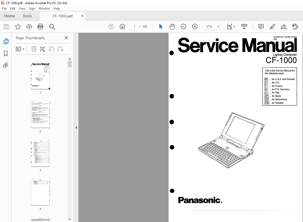
ORDER NO: CPD 9211019 CO G22
Description
Panasonic CF-1000 Laptop Computer Service Manual – PDF DOWNLOAD
Safety Precaution
1. System Overview
1.1 General Description
The CF-1000 is based on the Am386SXLV microprocessor and can be run up to 25 MHz.
The disk drives are a 2.5-inch 60 megabytes hard disk and a 3.5-inch 1.44 megabytes floppy disk drive.
It is possible to remove the FDD pack and the optional battery pack can be attached in the space from which the FDD
pack was removed.
The system supports up to 12 megabytes of RAM (Total}; 4 megabytes are placed on the main logic board and an
additional 4 or 8 megabytes can be added using optional RAM card.
Both system BIOS and video BIOS can be in shadow RAM.
The system uses pagemode memory to attain virtual zero-wait-state operation.
Standard ports include two serial (one port is mainly used with a MODEM}, one parallel, one external mouse or one
external keyboard (IBM-PS/2 style mini DIN size}.
The VGA interface is on the main logic board and it supports an analog monitor and a 640 x 480 black and white liquid
cr1sta! display.
The AT bus port socket is present for optional docking unit.
Panasonic CF-1000 Laptop Computer Service Manual – PDF DOWNLOAD
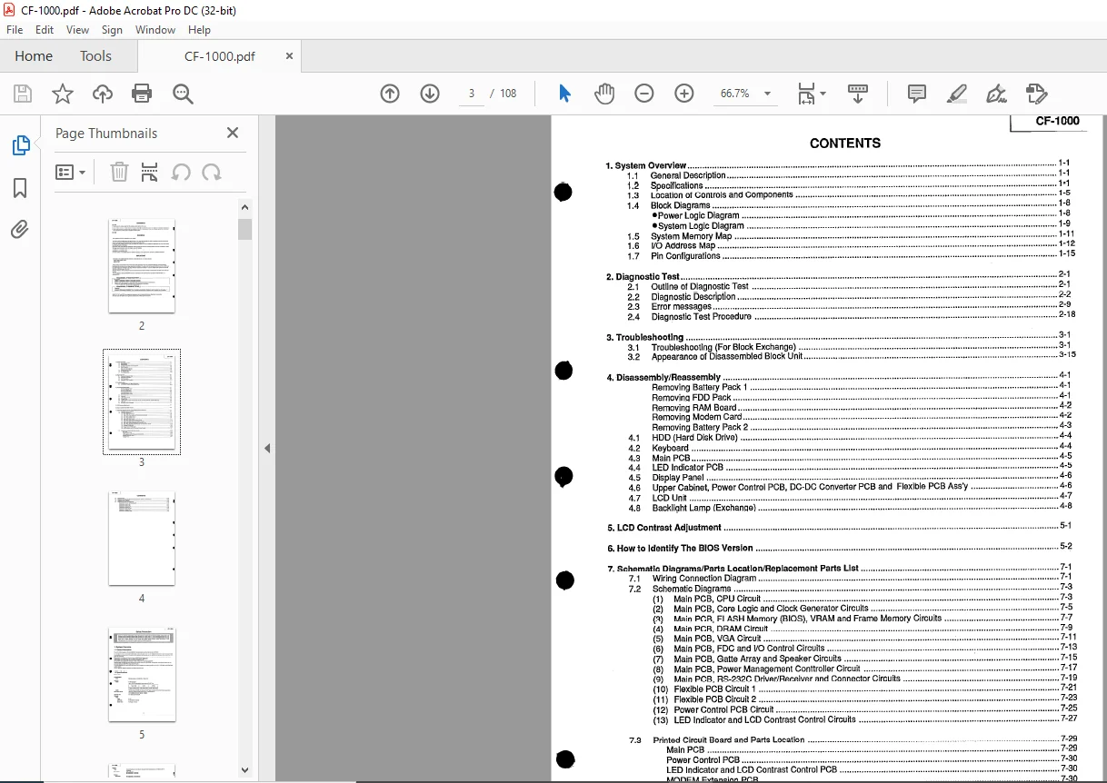
1 System Overview 1-1
11 General Description 1-1
12 Specifications 1-1
13 Location of Controls and Components 1-5
14 Block Diagrams 1-8
Power Logic Diagram 1-8
System Logic Diagram 1-9
15 System Memory Map 1-11
16 1/0 Address Map 1-12
1 7 Pin Configuiations 1-15
2 Diagnostic Test 2-1
21 Outline of Diagnostic Test 2-1
22 Diagnostic Description 2-2
23 Error messages 2-9
24 Diagnostic Test Procedure 2-18
3 Troubleshooting 3-1
31 Troubleshooting (For Block Exchange) 3-1
32 Appearance of Disassembled Block Unit 3-15
4 Disassembly/Reassembly 4-1
Removing Battery Pack 1 4-1
Removing FDD Pack 4-1
Removing RAM Board 4-2
Removing Modem Card 4-2
Removing Battery Pack 2 4-3
42 Keyboard 4-4
43 Main PCB 4-5
44 LED Indicator PCB 4-5
45 Display Panei 4-6
46 Upper Cabinet, Power Control PCB, DC-DC Converter PCB and Flexible PCB Ass’y 4-6
47 LCD Unit 4-7
48 Backlight Lamp (Exchange) 4-8
5 LCD Contrast Adjustment 5-1
5 He\: to !dant!fy The B!OS Version , 5-2
7 Schematic Diagrams/Parts Location/Replacement Parts List 7-1
71 Wiring Connection Diagram 7-1
72 Schematic Diagrams 7-3
(1) Main PCB, CPU Circuit 7-3
(2) Main PCB, Core Logic and Clock Generator Circuits 7-5
(3) Main PCB, FLASH Memory (BIOS), VRAM and Frame Memory Circuits 7-7
(4) Main PCB, DRAM Circuit 7-9
(5) Main PCB, VGA Circuit 7-11
(6) Main PCB, FDC and 1/0 Control Circuits 7-13
(7) fv1ain PCB, Gatta Array and Speaker Circuits ~ 7-15
(8) Main PCB, Power Management Conttroller Circuit 7-17
(9) Main PCB, RS-232C Driver/Receiver and Connector Circuits 7-19
(10) Flexible PCB Circuit 1 7-21
(11) Flexible PCB Circuit 2 7-23
(12) Power Control PCB Circuit 7-25
(13) LED Indicator and LCD Contrast Control Circuits 7-27
73 Printed Circuit Board and Parts Location 7-29
Main PCB 7-29
Power Control PCB 7-30
LED indicator and LCD Contrasi Conirol PCB 7=30
MODEM Extension PCB 7-30
Flexible PCB 7-31
CF-1000
CONTENTS
74 Exploded View 7-35
75 Replacement Parts List (Mechanical, Accessories, Packing, and Electrical) 7-37
76 Keyboard Parts Locations 7-43 A
77 Replacement Parts List (Keyboard) 7-45
Keyboard for USA and Canada (M) 7-45
Keyboard for English (E) 7-46
Keyboard for French (F) 7-47
Keyboard for German (G) 7-48
Keyboard for Italian (In 7-49
Ki:yhn~rrl fnr ~p~ni~h (~P) ,,u,, u,,, 7_,:;;;n
Keyboard for Swiss (SS) 7-51
Keyboard for Swedish (SW) 7-