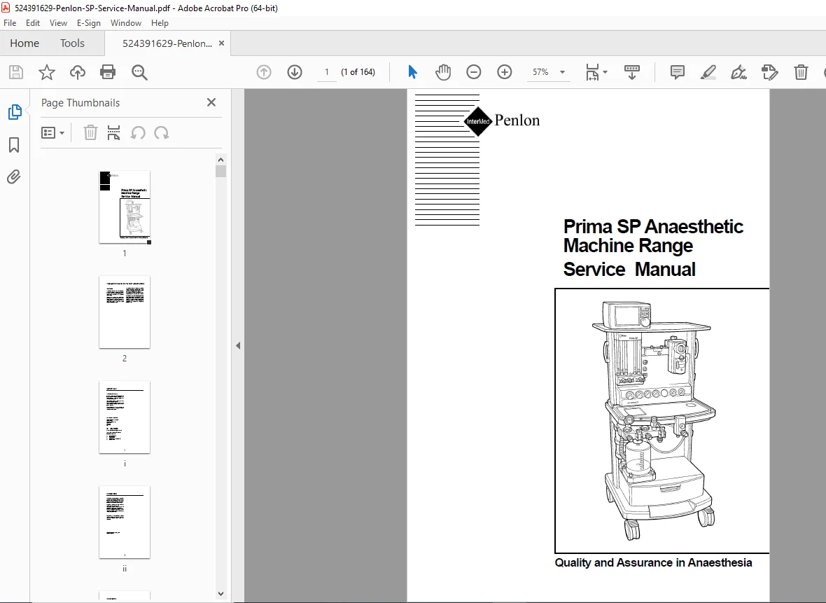
Penlon Prima SP Anaesthetic Machine Service Manual PDF
Original price was: $95.00.$18.95Current price is: $18.95.
Complete 164-page factory service manual for Penlon Prima SP anaesthetic machine range (SP 101/SP 102 models). Comprehensive technical documentation covering gas delivery systems (O2/N2O/Air/CO2), mechanical AHD (Anti-Hypoxic Device), flowmeters, vaporizers (Selectatec/Cagemount), oxygen monitoring, pressure regulators, safety devices, pre-use checks, function tests, fault diagnosis, service schedules (6/12/24/72-month), detailed servicing procedures, MRI compatibility, and spare parts lists for biomedical engineers.
Description
Penlon Prima SP Anaesthetic Machine Service Manual – Complete Repair Guide PDF DOWNLOAD
DESCRIPTION
Official Factory Service Manual for Penlon Prima SP Anaesthetic Machine Range
This authentic Penlon service manual PDF provides complete factory-authorized technical documentation for servicing, repairing, and maintaining the Prima SP anaesthetic (anesthesia) machine range manufactured by Penlon Limited, UK. Essential for biomedical equipment technicians (BMETs), clinical engineering departments, hospital maintenance staff, and anesthesia equipment service specialists responsible for this critical anaesthetic delivery system.
FILE DETAILS
- Manual Name: Prima SP Anaesthetic Machine Range Service Manual
- Models Covered: Prima SP 101, Prima SP 102
- Manufacturer: Penlon Limited (Abingdon, UK)
- Publication Year: 2004 (optimized for Acrobat Distiller 6.0)
- PDF Quality: Excellent – Factory diagrams and technical schematics
- Total Pages: 164 pages
- Language: English
- Page Size: A4 (595 x 842 pts)
- Copyright: Penlon Limited, 2004
MODELS COVERED
Prima SP 101:
- Compact anaesthetic machine
- Frame size: 139 x 45 x 70 cm (H x W x D)
- Maximum 3 cylinder yoke assemblies
- Weight: approximately 70 kg (154 lb)
- Work surface: 45 x 25 cm
- Top shelf: 58.5 x 35 cm
Prima SP 102:
- Extended anaesthetic machine
- Frame size: 139 x 71 x 70 cm (H x W x D)
- Maximum 4 cylinder yoke assemblies
- Weight: approximately 75 kg (165 lb)
- Work surface: 58 x 25 cm
- Top shelf: 71 x 35 cm
Common Features:
- Work surface height: 86 cm
- Front-braked castors for mobility
- Ventilator bellows post (25.4 mm or 22 mm poles, 30 kg capacity)
- Base drawer storage
- Gas scavenging bracket (30 kg capacity)
- 22 mm male taper CGO with coaxial 15 mm female taper, Safelock fitting
COMPREHENSIVE SECTION BREAKDOWN
USER RESPONSIBILITY & WARNINGS
Critical Safety Information:
- Patient monitoring importance and anaesthetic drug variation warnings
- Requirement for qualified anaesthetist control
- Respiratory and cardiovascular system monitoring protocols
- Machine control parameters vs. clinical observations
- Service requirement for Penlon-trained engineers only
Contact Information:
- Technical Support Department (Penlon Limited, Abingdon Science Park)
- Phone: +44 (0) 1235 547076
- Fax: +44 (0) 1235 547062
SECTION 1: WARNINGS AND CAUTIONS (Pages 02-04)
Comprehensive Safety Guidelines:
- Gas delivery hazards (injury/death prevention)
- Electrical safety requirements
- High-pressure gas handling
- Vaporizer safety protocols
- Patient breathing system precautions
- Maintenance safety procedures
SECTION 2: PURPOSE (Page 05)
- Machine application overview
- Clinical use parameters
- Operational scope definition
SECTION 3: DESCRIPTION (Pages 06-23)
3.1 Framework and General Construction:
- Modular design philosophy
- Structural integrity features
- Mobility and stability systems
- Work surface and storage configurations
3.2 Gas Circuit (Non-AHD Machines):
- Complete gas flow pathways
- Component interconnections
- Pressure regulation stages
3.3 Gas Circuit Schematic:
- Detailed pneumatic diagrams for:
- Air delivery
- Oxygen delivery
- CO2 delivery (UK specification)
- N2O delivery
- Flowmeter assembly layouts
- Gas tray configuration
- Pneumatic pressure sources
- Filter locations
- Pressure regulators
- Non-return valve positions
- Reservoir integration
- Pressure relief valve placement
- Vaporizer mounting
- Common Gas Outlet (CGO) connections
3.4 Gas Supply Safety Devices:
Gas Supply Cut-off Device:
- Triggered by low oxygen supply pressure
- Cut-off activation: 186 ±14 kPa (27 ±2 psig)
- Reinstated at: 227 ±14 kPa (33 ±2 psig)
- Affects nitrous oxide and carbon dioxide supplies
Oxygen Supply Failure Warning Whistle:
- Audible warning for oxygen pressure reduction
- Starts sounding at: 200 ±21 kPa (29 ±3 psig)
- Continues until: approximately 70 kPa (10 psig)
- Minimum 7-second warning duration
- Oxygen consumption: approximately 2 L/min when sounding
- Oxygen reservoir provides extended warning time
Oxygen Supply Visual Indicator:
- GREEN when supply at working pressure
- RED when pressure falls
- Immediate visual feedback
Air/N2O Interlock (Optional):
- User switchable between Air and Nitrous Oxide
- Machine will NOT deliver Air/N2O mixture simultaneously
- O2/N2O linkage continues on Mechanical AHD machines
CO2 Flow Restriction:
- Maximum flow restricted to 500 ml/min
- Pre-set flow control valve (non-adjustable)
- Not available on US specification machines
Fresh Gas Pressure Relief Valve:
- Prevents fresh gas delivery >41 kPa (6 psi)
- Protects against total CGO blockage
- Mounted between vaporizer back bar and CGO
Low Pressure Gas Tubing:
- Diameter-indexed for safety:
- Oxygen: 8 mm
- Nitrous oxide: 6 mm
- Air: 5 mm
- Mixed gas: 10 mm
- Carbon Dioxide: 4 mm
- Helium: 4 mm
- Xenon: 4 mm
3.5 Mechanical AHD (Anti-Hypoxic Device):
System Design:
- Gear linkage between oxygen control valve and N2O needle valve
- Maintains minimum 30% ±3% oxygen concentration in O2/N2O mixture
- Housed within flowmeter module
Gas Delivery Switch:
- Controls oxygen supply to entire system
- Must be in ‘On’ position for normal operation
- Triggers gas cut-off for all gases at predetermined O2 pressure
Operational Principle:
- Primary valve in N2O flow controlled by oxygen control knob
- Secondary N2O valve provides additional restriction only
- Prevents hypoxic mixture delivery throughout flow range
3.6 Pressure Gauges:
- Pipeline supply pressure indication
- Cylinder contents monitoring
- Clarity and accuracy specifications
- Color-coded for gas identification
3.7 Flowmeters and Controls:
- Flow ranges: 0-10 L/min (O2, N2O, Air, Helium)
- Cascade flow tubes: 0-1000 ml/min and 0-10 L/min
- CO2: 0-500 ml/min (flow limited)
- Accuracy: ±2.5% of full scale reading
- Anti-static coating on tubes
- Length-indexed tubes:
- Oxygen: 260 mm (10.24 inch)
- Nitrous oxide: 250 mm (9.84 inch)
- Other gases: 240 mm (9.45 inch)
- Scale length: 152 mm (6 inch) minimum
- Matched tubes and floats (non-interchangeable)
3.8 Vaporizers:
- Selectatec compatible back bar system
- Cagemount system compatibility
- Interlock system prevents multiple vaporizer operation
- O-ring seals (no lubrication required)
- Pillar valve specifications
3.9 Common Gas Outlet (CGO) Block:
- 22 mm male taper with coaxial 15 mm female taper
- Safelock fitting for secure connections
- Pressure relief valve integration
- Clippard valve design
3.10 Electrical Power Supply:
- Mains voltage specifications
- Output socket configurations
- Power distribution
- Safety testing requirements
3.11 Third/Fourth Gas Options:
- Helium delivery capability
- Xenon delivery capability
- Special order configurations
- Pin-indexed cylinder yokes
3.12 Auxiliary Gas Outlets:
- Two self-sealing oxygen connections
- Flow rate specifications:
- Not less than 100 L/min to free air
- 80 L/min against 243 kPa (36 psig) resistance
- 70 L/min against 270 kPa (40 psig) resistance
- Pipeline and cylinder supply options
3.13 Oxygen Monitor:
- Sensor placement and calibration
- Alarm settings (high and low)
- Display specifications
- Battery replacement procedures
3.14 A100 and A100SP Absorber:
- Circle system compatibility
- CO2 absorption specifications
- Canister replacement procedures
- User information
3.15 Prima SP – MRI Compatibility:
- Non-ferromagnetic component specifications
- Safe distance requirements
- Operational limitations in MRI environment
- Special considerations for magnetic fields
SECTION 4: SPECIFICATION (Pages 24-30)
4.1 Physical Dimensions:
- Complete frame dimensions
- Work surface specifications
- Shelf loading capacities (30 kg evenly distributed)
- Drawer dimensions and capacity (10 kg)
- Castor specifications
- Weight specifications
4.2 Gas Supplies:
Cylinder Options:
- SP 101: Maximum 3 cylinders
- SP 102: Maximum 4 cylinders
- Pin-indexed yokes for safety
- Gases: Oxygen, Nitrous oxide, Air, Carbon dioxide
- Special order: Helium, Xenon
Pipeline Options:
- Maximum 3 pipelines (O2, N2O, Air)
- National standards compliance
Medical Gas Color Codes:
- Oxygen: White or Green
- Nitrous oxide: Blue
- Medical air: Black/White or Yellow
- Carbon dioxide: Grey
- Helium: Brown
- Xenon: Green (bright)
4.3 Flowmeters:
- Flow ranges and accuracy specifications
- Construction and dimensions
- Length indexing system
- Anti-static coatings
4.4 Gas Pressures:
Pipeline Supplies:
- USA/Canada/Japan: 340 kPa (50 psig)
- UK: 400 kPa (58 psig)
Cylinder Supplies (at 5 L/min flow):
- USA/Canada/Japan: 310 kPa +15/-35 kPa
- UK: 380 kPa +15/-35 kPa
Regulator Safety:
- Diaphragm bursting pressure: 2800 kPa (406 psig)
- Reduced pressure safety valve: 600 kPa (87 psig)
Secondary Regulators (at 5 L/min flow):
- O2 and N2O: 152-241 kPa (22-35 psi)
- Air: 207-283 kPa (30-41 psi)
- Pre-March 2002 machines (all gases): 207-283 kPa
Safety Valve:
- 41 kPa ±10% (6 psi ±10%) to protect flowmeter and vaporizer
4.5 Auxiliary Gas Outlets:
- Pipeline supply at pipeline pressure
- Cylinder supply at reduced regulator pressure
- Flow rate specifications
4.6 Oxygen Failure Warning Devices:
- Whistle operation parameters
- Visual indicator specifications
- Gas cut-off trigger points
4.7 Oxygen Flush:
- Emergency flow rate: 35-75 L/min
- Activation mechanism
- Safety features
4.8 Mechanical AHD Systems:
- Minimum O2 concentration: 30% ±3%
- Operating range specifications
- Gear ratio and linkage parameters
4.9 Environmental:
- Operating temperature ranges
- Storage temperature ranges
- Humidity specifications
- Atmospheric pressure ranges
4.10 Third and Fourth Gas Options:
- Helium specifications
- Xenon specifications
- Flow control parameters
4.11 Electrical Supply:
- Voltage and frequency requirements
- Power consumption specifications
- Socket ratings and configurations
4.12 Oxygen Monitor:
- Sensor type and specifications
- Calibration parameters
- Alarm thresholds
- Battery type and replacement schedule
SECTION 5: PRE-USE CHECKS (Pages 31-48)
5.1 Pre-use Check List:
- Complete daily check procedures
- Safety verification steps
- Documentation requirements
5.2 Pre-use Checks (Non-AHD Machines):
- Step-by-step visual inspection
- Control functionality verification
- Gas supply confirmation
- Leak detection procedures
5.3 Pre-use Checks (Machines with Mechanical AHD):
- AHD linkage verification
- Oxygen concentration testing
- Gas delivery switch operation
- Basal flow confirmation (100-200 ml/min depending on model)
5.4 Leak Rate Check:
- Test equipment requirements
- Pressure decay testing
- Acceptable leak rates
- Troubleshooting excessive leaks
5.5 Electrical Supply:
- Power connection verification
- Socket functionality testing
- Ground continuity checks
5.6 Patient Breathing System:
- Circuit integrity testing
- One-way valve operation
- APL valve functionality
- Breathing bag compliance
5.7 Oxygen Flush:
- Flow rate verification (35-75 L/min)
- Control operation smoothness
- Safety lock-out testing
5.8 Anaesthetic Gas Scavenge System (AGSS):
- Connection verification
- Flow rate adequacy
- Vacuum level testing
5.9 Alarm System Testing:
- Oxygen failure whistle (minimum 7 seconds)
- Visual indicator operation (GREEN to RED)
- Gas cut-off verification
- Oxygen monitor alarms (if fitted)
5.10 Vaporizers:
- Filling level verification
- Interlock system operation
- Back bar security
- O-ring integrity
5.11 Ventilator:
- Connection verification
- Power supply testing
- Alarm functionality
5.12 Oxygen Monitor:
- Sensor placement verification
- Calibration in room air (21% ±2%)
- 100% oxygen testing
- Alarm threshold verification
SECTION 6: FUNCTION TEST (Pages 49-58)
6.1 Introduction:
- Test equipment requirements
- Safety precautions
- Documentation procedures
6.2 Machine Frame:
- Structural integrity inspection
- Castor operation and braking
- Drawer and tablet movement
- Attachment security
6.3 Electrical Safety Tests:
- Earth continuity testing
- Insulation resistance testing
- Earth leakage current testing
- Touch current testing
- Mains lead and plug inspection
6.4 Pipeline Gas Supply and Non-Return Valve:
- Anti-confusion checks
- Pressure leak testing
- Non-return valve operation verification
- Connector cleanliness and damage inspection
6.5 Cylinder Gas Supply and Pressure Reducing Valves:
- Yoke assembly inspection
- Pin-indexing verification
- Bodok seal replacement
- Pressure gauge accuracy
- Regulator output pressure testing
- Primary regulator: varies by region
- Secondary regulator testing
- Leak testing procedures
6.6 Flowmeter Unit:
- Control valve smooth operation
- Positive off-position verification
- Basal flow testing:
- All models (pre-March 2002): 100-200 ml/min
- Cascade O2 flowmeter (March 2002 onwards): 50-75 ml/min
- Single O2 flowmeter (March 2002 onwards): 100-200 ml/min
- Float movement and rotation checking
- Maximum flow capability verification
- CO2 flow restriction testing (500-600 ml/min)
6.7 Gas Safety Devices:
- Mechanical AHD testing at multiple O2 flow rates
- O2 concentration verification (27-33% at specified flows):
- 0.25 L/min O2 (cascade models)
- 0.5 L/min O2
- 0.8 L/min O2
- 1.5 L/min O2
- 3.0 L/min O2
- Gas delivery switch operation
- Air/N2O interlock functionality
- Oxygen failure alarm testing
- Visual indicator operation
- Gas cut-off verification
6.8 Vaporizers and Back Bar Manifold Assembly:
- Selectatec O-ring replacement
- Pillar valve operation and sealing
- Insert inspection (flush or proud, not sunken)
- Interlock system verification
- Cagemount: flexible hose and taper connector inspection
- Fomblin or oxygen-safe grease application
6.9 Reduced Pressure Gas Circuit Leakage:
- Fresh gas pressure relief valve testing (41 kPa ±10% at 10 L/min)
- Leak test from flowmeter to CGO
- Manometer test at 20 kPa (3 psi)
- Maximum permissible flow: 200 ml/min
- Testing with/without vaporizers (ON and OFF positions)
6.10 Emergency Oxygen Flush Control Test:
- Flow rate verification: 35-75 L/min
- Control operation smoothness
- Safety mechanisms
6.11 Auxiliary Outlets:
- Security and damage inspection
- Lock and release movement
- Dynamic flow rate testing
- Oxygen fail whistle non-operation verification
SECTION 7: FAULT FINDING (Pages 59-68)
7.1 Introduction:
- Systematic troubleshooting approach
- Safety considerations during fault diagnosis
- Test equipment requirements
7.2 Fault Diagnosis Table:
Flowmeter Issues:
- Restricted flow symptoms → Cylinder/pipeline/filter/valve problems
- Float level falls → Reducing valve, leak, or blockage issues
- Worn needle valve → Complete valve assembly replacement
Vaporizer Mounting Issues:
- Back bar leakage → Loose screws, missing O-seals
- Vaporizer difficult to remove → Damaged seals or locking system
- Gas valve leakage → Valve replacement
Gas Cut-off Problems:
- No N2O/third/fourth gas → O2 supply not on, delivery switch off
- Restricted N2O flow → Faulty safety capsule valve
- Shuttle or seal defects → Capsule valve replacement
- Vent port blockage → Component cleaning
Warning Whistle Failures:
- Whistle leakage → Loose connection or faulty whistle
- Continuous sounding → Faulty whistle or low circuit pressure
- Fails to sound → Whistle replacement or pressure issues
Pressure Gauge Problems:
- Inaccurate readings → Gauge replacement
- Needle sticking → Gauge replacement
- No reading → Supply problem or gauge failure
Pipeline Supply Issues:
- Low/no pressure → Supply problem, connector issues
- Leakage → Connection problems, hose damage
Cylinder Supply Issues:
- Low/no flow → Empty cylinder, valve closed, regulator failure
- Pressure drops rapidly → Cylinder leak, regulating valve failure
SECTION 8: SERVICE SCHEDULE (Pages 69-81)
8.1 Service Schedule Overview:
- Six Month Service (at 6, 18, 30, 42, 54, 66 months)
- Twelve Month Service (Annual service)
- Twenty-four Month Service (Two-year service)
- Seventy-two Month Service (Six-year service)
8.2 Six Month Service Checks (Pages 72-74):
Machine Frame:
- Structural integrity and attachment security
- Damage inspection
- Wheel movement and front braking
- Drawer and tablet operation
Electrical Safety:
- Mains lead and plug inspection
- Electrical safety tests per country requirements
- Output socket functionality
Pipeline Hoses:
- Connector, probe, and hose inspection
- Anti-confusion checks
- Pressure leak testing (cylinders removed, Gas Delivery Switch OFF)
Cylinder Yokes:
- Damage and cleanliness inspection
- Tight fittings and screw freedom
- Bodok seal replacement (no grease/lubricant)
Pressure Gauges and Regulators:
- Gauge clarity and damage inspection
- Smooth needle movement
- Cylinder gas supply leak testing (Gas Delivery Switch ON, O2 basal flow blanked)
- Primary regulator output pressure verification
- Secondary regulator output pressure verification
Flowmeter and Mechanical AHD:
- Control valve smooth operation and positive off
- Basal flow verification (model-specific values)
- Flow tube and bobbin inspection
- Float rotation verification
- Maximum flow capability testing
- CO2 flow restriction verification (500-600 ml/min)
- O2 monitor connection to CGO
- N2O/Air selection switch operation
- Mechanical AHD O2 concentration testing at multiple flow rates (27-33%)
- Gas delivery switch operation
Oxygen Fail Alarms:
- Simulate O2 failure (unplug pipeline)
- Whistle duration minimum 7 seconds
- N2O and CO2 cut-off verification
- Visual indicator operation (GREEN to RED)
- Cylinder test repetition
Back Bar Assembly:
- Selectatec O-ring replacement (no grease/lubricant)
- Pillar valve operation and sealing
- Insert proud/flush verification
- Interlock system operation
- Cagemount: hose and taper connector inspection with Fomblin lubrication
Fresh Gas Pressure Relief Valve:
- CGO occlusion with manometer
- Relief at 41 kPa ±10% at 10 L/min O2 flow
Leak Testing:
- Flowmeter to CGO leak test
- 20 kPa (3 psi) pressure maintenance
- Maximum 200 ml/min permissible flow
- Testing with/without vaporizers
CGO Checks:
- Security and movement freedom
- Safelock O-ring inspection (no grease/lubricant)
- O2 emergency flush: 35-75 L/min
Auxiliary Outlets:
- Security, damage, lock/release movement
- Dynamic flow rate testing
Oxygen Monitor:
- Sensor testing in 100% O2
- Air calibration (21% ±2%)
- Alarm adjustment and triggering
- Sensor location restoration
Final Concentration Tests:
- Gas concentration verification
- Flow rate vs. flowmeter correspondence
- 3 L/min O2 + N2O: 50% ±2%
- 0.5 L/min O2 + N2O: 50% ±2%
- CO2 test (if fitted)
- 3 L/min Air + O2: 60% ±2%
Test Completion:
- Equipment removal
- Gas drainage
- Gas delivery switch OFF
- Service record completion
8.3 Twelve Month Service Checks (Pages 75-77):
- All six-month checks PLUS:
- Extended electrical safety testing
- Vaporizer calibration verification
- Advanced leak testing
- Component wear assessment
- Detailed documentation
8.4 Twenty-four Month Service Checks (Page 78):
- All twelve-month checks PLUS:
- Major component replacement schedule
- Extended calibration procedures
- Comprehensive safety testing
8.5 Seventy-two Month Service Checks (Pages 78-81):
- Complete system overhaul
- All major component replacement
- Full recalibration
- Comprehensive testing protocol
SECTION 9: SERVICING PROCEDURES (Pages 82-110)
9.1 Servicing Guidelines:
- Authorized personnel requirements
- Safety precautions
- Tool requirements
- Component handling
9.2 Ancillary Equipment:
- Breathing systems
- Vaporizers
- Ventilators
- Monitoring equipment
9.3 Cleaning and Sterilisation:
- Approved cleaning agents
- Sterilization methods
- Component-specific procedures
- Safety during cleaning
9.4 Gas System Components:
- Component identification
- Replacement procedures
- Testing after replacement
9.5 Internal Gas Pipework:
- Diameter-indexed tubing replacement
- Connection procedures
- Leak testing
9.7 Front Cover – Remove and Refit:
- Cover removal steps
- Access to internal components
- Reassembly procedures
9.7 Flowmeter Cover:
- Cover removal for service access
- Reinstallation and verification
9.8 Mechanical AHD System:
- Complete service procedures
- Linkage adjustment
- Calibration verification
9.9 Basal Flow Check – O2 Concentration Check – Gear Linkage Reset:
- Basal flow measurement
- O2 concentration verification at multiple flows
- Gear linkage adjustment procedures
- Troubleshooting out-of-specification readings
9.10 Control Valve Capsule Removal/Replacement:
- Capsule removal procedures
- O-ring replacement
- Installation torque specifications
- Post-installation testing
9.11 Oxygen Reservoir – Removal/Replacement:
- Reservoir location and access
- Removal procedures
- Installation and leak testing
9.12 Secondary Regulators:
- Regulator removal
- Pressure adjustment procedures
- Installation and testing
- Output pressure verification
9.13 Gas Block – Remove and Refit:
- Complete gas block removal
- Component access
- Reassembly procedures
- Comprehensive leak testing
9.14 Selectatec Compatible Manifold Block:
- Manifold removal
- O-ring replacement
- Pillar valve service
- Interlock mechanism maintenance
9.15 Gas Delivery Switch:
- Switch removal and replacement
- Electrical and pneumatic connections
- Operation testing
9.16 Air/N2O Interlock Switch:
- Switch removal procedures
- Replacement installation
- Interlock functionality testing
9.17 Oxygen Failure Visual Indicator:
- Indicator removal
- Replacement procedures
- Operational verification
9.18 CGO – Clippard Valve Replacement:
- Valve access and removal
- New valve installation
- Leak testing
- Pressure relief verification
9.19 Flowmeter Tubes – Removal:
- Tube and float removal procedures
- Matched set identification
- Installation of replacement tubes
- Calibration verification
9.20 Flowmeter Assembly – Removal:
- Complete flowmeter module removal
- Disconnection procedures
- Reinstallation and testing
9.21 Flowmeter Lighting – Removal:
- Light source access
- Bulb replacement
- Electrical connection verification
9.22 Oxygen Monitor – Battery Replacement:
- Battery type identification
- Replacement procedures
- Calibration after battery change
9.23 Oxygen Monitor Sensor:
- Sensor removal and replacement
- Calibration procedures
- Storage and handling
9.24 A100 Circle System Absorber – Removal:
- Absorber removal procedures
- Canister replacement
- Seal inspection
- Reinstallation
SECTION 10: SPARE PARTS LIST (Pages 111-139)
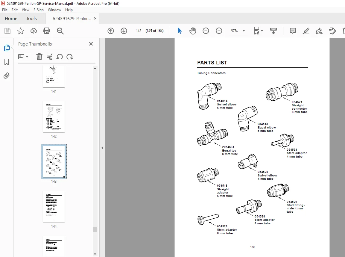
Comprehensive Parts Catalog:
- Part numbers and descriptions
- Exploded view diagrams
- Component assemblies
- Recommended spare inventory
- Preventive maintenance kit part numbers
- Critical components list
- O-ring specifications
- Gasket and seal references
Major Assemblies:
- Flowmeter assembly parts
- Gas block components
- Regulator parts
- Valve assemblies
- Back bar components
- CGO parts
- Electrical components
SECTION 11: APPENDIX (Pages 140-145)
Care of Back-up Battery:
- Battery maintenance
- Storage requirements
- Replacement schedule
- Disposal procedures
Product Classification and Labelling Terminology:
- Medical device classifications
- Warning labels
- Compliance markings
- Serial number identification
Wiring Diagram – Lighting:
- Complete electrical schematic
- Circuit descriptions
- Component identification
- Troubleshooting guide
Wiring Diagram – General:
- Complete electrical system
- Power distribution
- Safety circuits
- Monitoring connections
Tightening Torques:
- Torque specifications for all fasteners
- Thread sizes and materials
- Assembly sequences
- Special handling notes
A100SP Absorber User Information:
- Absorber specifications
- Canister capacity
- Change indicators
- Safety information
KEY TECHNICAL FEATURES
✓ Mechanical AHD system maintaining 30% ±3% minimum O2 concentration
✓ Multi-gas delivery (O2, N2O, Air, CO2, optional Helium/Xenon)
✓ Oxygen failure warning (7-second minimum audible alarm)
✓ Gas cut-off device triggered at 186 ±14 kPa
✓ Flowmeter accuracy ±2.5% of full scale reading
✓ Pressure relief valve at 41 kPa ±10% for patient safety
✓ Diameter-indexed tubing for gas identification
✓ Selectatec and Cagemount vaporizer compatibility
✓ MRI compatibility with non-ferromagnetic construction
✓ Comprehensive service schedules (6/12/24/72-month intervals)
✓ Detailed fault diagnosis tables for systematic troubleshooting
✓ Complete spare parts catalog with part numbers
✓ Electrical safety testing procedures
WHO NEEDS THIS MANUAL?
- Biomedical Equipment Technicians (BMETs) servicing anaesthetic machines
- Clinical Engineering Departments maintaining hospital anaesthesia equipment
- Hospital Maintenance Staff responsible for operating room equipment
- Anaesthesia Equipment Service Specialists performing repairs and calibrations
- Medical Equipment Repair Facilities authorized for Penlon service
- Technical Training Programs teaching anaesthetic machine maintenance
- Healthcare Technology Management (HTM) departments
- Operating Theatre Technical Staff performing pre-use checks
- Penlon-Trained Engineers requiring comprehensive technical documentation
- Medical Device Regulatory Compliance Officers verifying safety protocols
CRITICAL SYSTEMS COVERED
Gas Delivery System:
- Multi-gas pneumatic circuits
- Pressure regulation (primary and secondary)
- Flow control and metering
- Safety cut-off mechanisms
- Anti-hypoxic device (AHD) operation
Safety Systems:
- Oxygen failure warning (audible and visual)
- Gas cut-off device for N2O and CO2
- Fresh gas pressure relief valve
- Mechanical AHD minimum O2 guarantee
- Diameter-indexed tubing
- Pin-indexed cylinder yokes
Monitoring Systems:
- Oxygen concentration monitoring
- Pressure gauges (pipeline and cylinder)
- Visual indicators
- Alarm systems
Vaporizer Systems:
- Selectatec compatible manifold
- Cagemount system
- Interlock mechanisms
- Back bar assembly
Electrical Systems:
- Mains power supply
- Output sockets
- Lighting circuits
- Safety testing protocols
Stop relying on incomplete online information and unauthorized third-party guides! This official Penlon factory service manual provides instant access to complete pneumatic schematics, detailed mechanical AHD calibration procedures, comprehensive safety device testing protocols, and professional fault diagnosis tables. Download now and service your Prima SP anaesthetic machine with the same technical documentation used by certified Penlon-trained engineers and authorized service centers worldwide. Ensure patient safety and regulatory compliance with factory-authorized maintenance procedures!