Perkins 1204F-E44TA and 1204F-E44TTA Industrial Engines Disassembly & Assembly Manual – PDF DOWNLOAD
Original price was: $65.95.$31.95Current price is: $31.95.
Perkins 1204F-E44TA and 1204F-E44TTA Industrial Engines Disassembly & Assembly Manual
Description
Perkins 1204F-E44TA and 1204F-E44TTA Industrial Engines Disassembly & Assembly Manual
TABLE OF CONTENTS:
Perkins 1204F-E44TA and 1204F-E44TTA Industrial Engines Disassembly & Assembly Manual
Disassembly and Assembly Section
Fuel Priming Pump – Remove and Install
(Electric Fuel Lift Pump (EFLP)) 6
Flow Control Valve – Remove and Install 7
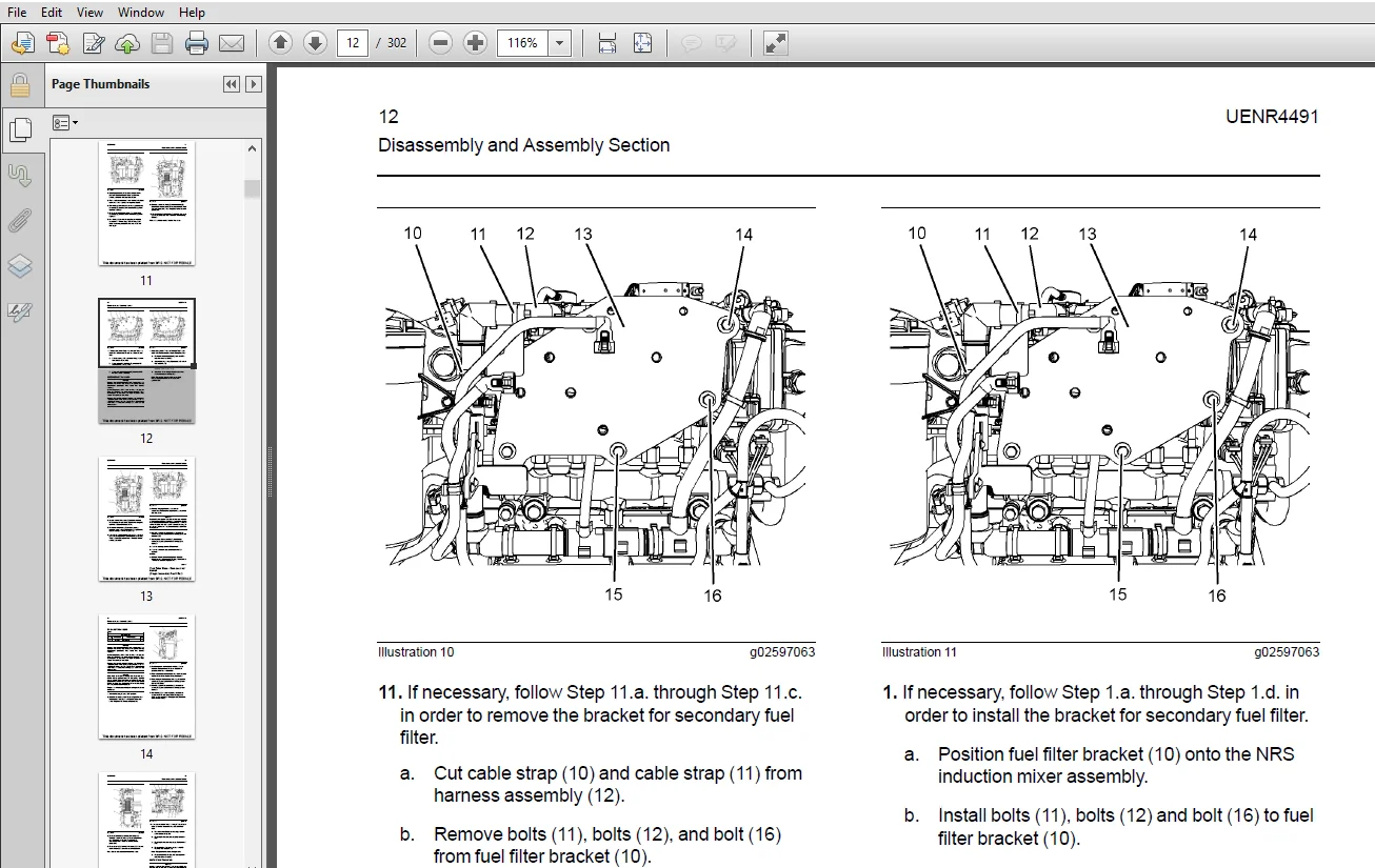
Fuel Filter Base – Remove and Install (Twin
Secondary Fuel Filter) 10
Fuel Filter Base – Remove and Install (Single
Secondary Fuel Filter) 13
Water Separator and Fuel Filter (Primary) –
Remove and Install 17
Fuel Manifold (Rail) – Remove and Install 20
Fuel Injection Lines – Remove 22
Fuel Injection Lines – Install 24
Exhaust Cooler (NRS) – Remove and Install (Top
Mounted Turbocharger) 26
Exhaust Cooler (NRS) – Remove and Install
(Side Mounted Turbocharger) 30
Exhaust Cooler (NRS) – Remove and Install
(Twin Turbochargers) 34
Inlet Air Control – Remove (NRS Induction
Mixer) 37
Inlet Air Control – Install (NRS Induction Mixer) 39
Fuel Injection Pump – Remove 42
Fuel Injection Pump – Install 44
Fuel Injection Pump Gear – Remove 46
Fuel Injection Pump Gear – Install 46
Electronic Unit Injector – Remove 47
Electronic Unit Injector – Install 50
Turbocharger – Remove (Second Stage
Turbocharger) 53
Turbocharger – Remove (First Stage
Turbocharger) 55
Turbocharger – Remove (Top Mounted
Turbocharger ) 56
Turbocharger – Remove (Side Mounted
Turbochargers) 57
Turbocharger – Install (Side Mounted
Turbochargers) 59
Turbocharger – Install (Second Stage
Turbocharger) 61
Turbocharger – Install (First Stage
Turbocharger) 63
Turbocharger – Install (Top Mounted
Turbocharger ) 66
Wastegate Solenoid – Remove and Install 68
Exhaust Back Pressure Valve – Remove and
Install 71
Clean Emissions Module – Remove and Install73
Diesel Exhaust Fluid Lines – Remove and
Install 75
Diesel Exhaust Fluid Pump – Remove and
Install 78
DEF Injector and Mounting – Remove and
Install 80
Diesel Exhaust Fluid Tank – Remove and
Install 83
Manifold (DEF Heater) – Remove and Install 85
Solenoid Valve (DEF Heater Coolant) – Remove
and Install 89
Flexible Exhaust Pipe – Remove and Install 90
Exhaust Manifold – Remove and Install (Twin
Turbochargers Exhaust manifold) 94
Exhaust Manifold – Remove and Install (Single
Turbocharger Exhaust Manifold) 97
Exhaust Elbow – Remove and Install 101
Exhaust Elbow – Remove and Install (Top
Mounted and Side Mounted Turbocharger
Exhaust Elbow) 102
Support and Mounting (CEM) – Remove and
Install 103
Inlet and Exhaust Valve Springs – Remove and
Install 105
Inlet and Exhaust Valves – Remove and
Install 109
Engine Oil Filter Base – Remove and Install 112
Engine Oil Cooler – Remove 113
Engine Oil Cooler – Install 114
Engine Oil Pump – Remove 115
Engine Oil Pump – Install 116
Water Pump – Remove 117
Water Pump – Install 118
Water Temperature Regulator – Remove and
Install 120
Flywheel – Remove 121
Flywheel – Install 122
Crankshaft Rear Seal – Remove 123
Crankshaft Rear Seal – Install 124
Flywheel Housing – Remove and Install (Wet
Back End Housing) 125
Flywheel Housing – Remove and Install
(Standard Housing) 128
Crankshaft Pulley – Remove and Install 131
Crankshaft Front Seal – Remove and Install 132
Crankshaft Front Seal – Remove and Install
(Crankshaft Front Seal for Heavy Duty Front
Cover) 133
Front Cover – Remove and Install 134
UENR4491 3
Table of Contents
Front Cover – Remove and Install (Heavy Duty
Front Cover) 136
Gear Group (Front) – Remove and Install 137
Gear Group (Front) – Remove and Install (Heavy
Duty Gear Group (Front)) 142
Idler Gear – Remove 151
Idler Gear – Install 153
Housing (Front) – Remove 156
Housing (Front) – Remove (Heavy Duty Housing
(Front)) 158
Housing (Front) – Install 159
Housing (Front) – Install (Heavy Duty Housing
(Front)) 162
Accessory Drive – Remove and Install
(Accessory Drive SAE “B”) 165
Accessory Drive – Remove and Install
(Accessory Drive SAE “A”) 168
Crankcase Breather – Remove 170
Crankcase Breather – Install 171
Valve Mechanism Cover – Remove and
Install 173
Rocker Shaft and Pushrod – Remove 175
Rocker Shaft – Disassemble 177
Rocker Shaft – Assemble 178
Rocker Shaft and Pushrod – Install 179
Cylinder Head – Remove 183
Cylinder Head – Install 187
Lifter Group – Remove and Install (Hydraulic
Lifter Group) 191
Camshaft – Remove and Install 192
Camshaft Gear – Remove and Install 194
Camshaft Bearings – Remove and Install 199
Engine Oil Pan – Remove and Install (Aluminum
and Pressed Steel Oil Pans) 200
Engine Oil Pan – Remove and Install (Cast Iron
Oil Pan) 204
Balancer – Remove 208
Balancer – Install 210
Piston Cooling Jets – Remove and Install 212
Pistons and Connecting Rods – Remove 214
Pistons and Connecting Rods – Disassemble 215
Pistons and Connecting Rods – Assemble 216
Pistons and Connecting Rods – Install 218
Connecting Rod Bearings – Remove (Connecting
Rods in Position) 220
Connecting Rod Bearings – Install (Connecting
Rods in Position) 221
Crankshaft Main Bearings – Remove and Install
(Crankshaft in Position) 222
Crankshaft – Remove 227
Crankshaft – Install 229
Crankshaft Timing Ring – Remove and Install 232
Crankshaft Gear – Remove and Install 233
Crankshaft Gear (Balancer Drive) – Remove and
Install 235
Bearing Clearance – Check 236
Refrigerant Compressor – Remove and
Install 237
Nitrogen Oxide Sensor – Remove and Install
(Nitrogen Oxide Sensor on Engine) 240
Nitrogen Oxide Sensor – Remove and Install
(Nitrogen Oxide Sensor Positioned in Original
Equipment Manufacture (OEM) Exhaust Tube
Assembly) 242
Atmospheric Pressure Sensor – Remove and
Install 243
Camshaft Position Sensor – Remove and
Install 244
Crankshaft Position Sensor – Remove and
Install 245
Coolant Temperature Sensor – Remove and
Install 246
Engine Oil Pressure Sensor – Remove and
Install 247
Fuel Temperature Sensor – Remove and
Install 248
Ammonia Sensor – Remove and Install
(Ammonia Sensor if Equipped) 249
Soot Antenna – Remove and Install 251
Temperature Sensor (Exhaust) – Remove and
Install (Selective Catalytic Reduction (SCR)
Temperature Sensor) 252
Temperature Sensor (DPF) – Remove and
Install 253
Temperature Sensor (Catalyst Inlet) – Remove
and Install 254
Temperature Sensor (Cooled Exhaust Gas) –
Remove and Install 255
Pressure Sensor (Cooled Exhaust Gas) –
Remove and Install (Differential Pressure
Sensor and Inlet Pressure Sensor) 256
Boost Pressure Sensor – Remove and Install 260
Inlet Manifold Temperature Sensor – Remove
and Install 260
Glow Plugs – Remove and Install 261
Alternator Belt – Remove and Install 263
Idler Pulley – Remove and Install (Grooved Idler
Pulley) 264
Idler Pulley – Remove and Install (Flat Idler
Pulley) 265
Belt Tensioner – Remove and Install 266
Fan – Remove and Install 267
4 UENR4491
Table of Contents
Fan Drive – Remove and Install 268
Electronic Control Module – Remove 268
Electronic Control Module – Install 272
Alternator – Remove 275
Alternator – Install 278
Electric Starting Motor – Remove and Install 281
Air Compressor – Remove and Install (Single
Cylinder Air Compressor) 282
Air Compressor – Remove and Install (Twin
Cylinder Air Compressor) 288
Index Section
Index 296
UENR4491 5
Table of
DESCRIPTION:
Perkins 1204F-E44TA and 1204F-E44TTA Industrial Engines Disassembly & Assembly Manual
Perkins disassembly and assembly manual include step-by-step pictures, which is very easy to follow. They indicate what tools are needed to pay attention and how to repair them. If the engine is carefully maintained it will deliver a long productive life and efficient performance marked by power and economy.
- This manual primarily contains information troubleshooting, servicing specifications, assemble and disassemble industrial engine Perkins 1204F series.
- Perkins manual covers recommended procedures to be followed when servicing engines. It also contains information on special tools required and basic safety precautions.
- Study this manual carefully and observe the following general precautions to prevent serious personal injury and to avoid damage to the engine, equipment, and parts. The manual in PDF format. You can work with this manual after installing Adobe PDF Reader.
Models:
MT Engine
MU Engine
1204F-E44TA
1204F-E44TTA
- The electronic product “Perkins Industrial Engine 1204F Series Disassembly and Assembly PDF Manual” is dealer’s software which contains full detailed information.
- We have the catalog “Perkins Industrial Engine 1204F Series Disassembly and Assembly PDF Manual” in stock and it is possible to order and buy it now. After you receive the software, we will send all instructions needed to install and provide the after-sale support.
IMAGES PREVIEW OF THE MANUAL:
PERKINS 1204F-E44TA AND 1204F-E44TTA INDUSTRIAL ENGINES DISASSEMBLY & ASSEMBLY MANUAL – PDF DOWNLOAD:
PLEASE NOTE:
- This is the SAME exact manual used by your dealers to fix your vehicle.
- The same can be yours in the next 2-3 mins as you will be directed to the download page immediately after paying for the manual.
- Any queries / doubts regarding your purchase, please feel free to contact [email protected]