Pioneer AVH-X5800BHS AVH-X5800DAB Service Manual DVD AV PDF
Original price was: $95.00.$16.95Current price is: $16.95.
Factory service manual for Pioneer AVH-X5800BHS, AVH-X5800DAB, and AVH-X5850TV DVD RDS AV receivers with touchscreen display. Covers complete repair procedures, circuit diagrams for 16 PCB sections, DVD laser mechanism LS2.5 module, Bluetooth integration, and DAB/HD radio tuners. Includes diagnosis flowcharts, error codes, touch panel calibration, exploded views, and electrical parts lists for professional car audio technicians
Description
Pioneer AVH-X5800BHS AVH-X5800DAB Service Manual DVD AV Receiver Repair PDF DOWNLOAD
DESCRIPTION
This comprehensive factory service manual provides complete technical documentation for the Pioneer AVH-X5800BHS, AVH-X5800DAB, and AVH-X5850TV DVD RDS AV Receivers. Essential for professional car audio technicians, this manual includes detailed circuit diagrams, troubleshooting procedures, and repair instructions for these advanced multimedia head units.
Models Covered
Primary Models:
- AVH-X5800BHS/XNUC – DVD RDS AV Receiver with Bluetooth and HD Radio
- AVH-X5800DAB/XNEU5 – DVD RDS AV Receiver with Bluetooth and DAB Digital Radio
- AVH-X5850TV/XNRD – DVD RDS AV Receiver with TV Tuner
Companion Manual Reference: This service manual should be used together with CRT5651 (Model CX-3311) covering the LS2.5 DVD Mechanism Module which includes:
- DVD Mechanism circuit descriptions
- Mechanical descriptions and theory
- DVD mechanism disassembly procedures
- Diagnosis and troubleshooting
- DVD-specific settings and adjustments
Key Features of Covered Models
Multimedia Playback:
- DVD/CD player with motorized disc mechanism
- USB media playback support
- Video and audio format compatibility
- High-resolution touchscreen display
Connectivity & Integration:
- Bluetooth® Module – Hands-free calling and audio streaming
- HD Radio (AVH-X5800BHS) – Digital broadcast reception
- DAB Digital Radio (AVH-X5800DAB) – European digital radio
- TV Tuner (AVH-X5850TV) – Television reception capability
- Multiple audio/video inputs and outputs
- Rear camera input compatibility
Audio Processing:
- Advanced DSP (Digital Signal Processing)
- Multiple audio source selection
- Line-level outputs for amplifier integration
- Built-in amplification
Display System:
- Touchscreen LCD panel with LED backlight
- Resistive touch panel technology
- Adjustable flicker control
- High-visibility color display
Technical Specifications
Power Requirements:
- Operating Voltage: 14.4V DC (automotive standard)
- Backup Current: 4.0 mA or less (memory retention)
- Refer to Owner’s Manual for complete electrical specifications
Laser Diode Characteristics:
- DVD Laser: 660-670 nm wavelength
- CD Laser: 780-800 nm wavelength
- Maximum Output (Focus Lens On):
- CD: 6.26 mW (emitting period: 9 seconds)
- DVD: 1.27 mW (emitting period: unlimited)
- Safety Classification: Class 1 laser product per IEC 60825-1:2007
- Internal Classification: Class 1M laser module
DVD Mechanism:
- Model: LS2.5 Mechanism Module
- Motorized disc loading/ejection
- Error detection and correction systems
- Pickup unit with dual laser assembly
Complete Service Manual Contents
Section 1: Service Precautions
1.1 Service Precautions:
- Regulatory compliance requirements (safety, radio, noise regulations)
- Laser safety guidelines – maintain 13cm minimum distance from focus lens
- Never view laser beam directly for more than 10 seconds
- Hot component warnings and locations:
- Mother PCB (Side A): C1313, IC1301
- Mother PCB (Side B): C1306, C1317, IC3191, IC2401, IC160, IC1201, IC351, IC1271
- DVD Mechanism Module top case and rear holders
- Heat sink safety precautions
1.2 Notes on Disassembly/Assembly:
- Always turn off power before disassembly
- Connector protection during service (prevent IC damage)
- Pickup unit electrostatic discharge (ESD) protection
- Shorting-solder treatment procedures (reference to CRT5651)
- Line process restoration after repair
1.3 Notes on Operation Check/Diagnosis:
- EJECT LOCK MODE for DVD Mechanism:
- Enter mode: Reset start while pressing [VOL+] and [REVERSE] keys
- Exit mode: Repeat entry procedure
- Used for diagnostic testing and mechanism troubleshooting
1.4 Notes on Replacing Parts:
- ESD protection for MOS-type ICs
- Grounded soldering iron requirements
- Static-protected tweezers usage (avoid metal tweezers)
- Assembly-level replacement requirements for integrated components
- Critical component identification
1.5 Notes on Adjustment:
- Post-repair adjustment requirements
- Calibration procedures
1.6 Other Considerations:
- Safety component replacement guidelines (marked with safety symbol)
- California Proposition 65 compliance notice
Section 2: Specifications
2.1 Technical Specifications:
- Complete electrical and mechanical specifications
- Backup current: 4.0 mA or less
- Additional specifications referenced in Owner’s Manual
2.2 Disc/Content Format:
- Supported disc formats (DVD, CD, and variants)
- Compatible file formats for USB playback
- Bluetooth® SIG certification
- DVD Format/Logo licensing information
Section 3: Basic Items for Service
3.1 Check Points After Servicing:
- Post-repair verification procedures
- Functional testing requirements
- Quality assurance checkpoints
3.2 PCB Locations:
- Detailed PCB identification and physical locations:
- Mother PCB (main system board)
- Service Unit (Monitor) – display control
- DVD Core Unit – disc playback processor
- Interface PCB – external connections
- Service Unit (Keyboard) – front panel controls
- PCB Unit (Service) – auxiliary circuits
3.3 Jigs List:
- Required service tools and jigs
- Specialized test equipment
- Measurement devices
3.4 Cleaning:
- Approved cleaning methods and materials
- Laser lens cleaning procedures
- PCB cleaning techniques
- Connector maintenance
Section 4: Block Diagram
4.1 Overall Connection Diagram:
- Complete system interconnection overview
- Bluetooth module (BT UNIT – Pioneer/SUNTEC, YWX5055)
- CN2901 connector (CKS6364-A)
- Drive unit connections
- Power distribution
4.2 System Block Diagram: Detailed functional blocks including:
- System controller architecture
- Audio/video signal processing paths
- Tuner modules (HD Radio/DAB depending on model)
- Bluetooth integration
- USB interface
- Display controller
- DVD mechanism interface
4.3 Power Supply System Figure:
- Voltage regulation circuits
- Multiple DC/DC converter sections:
- 2ch DC/DC converter circuits
- 1ch DC/DC converter circuits
- Power distribution to all subsystems
- Backup power management
- Automotive voltage input conditioning
Section 5: Diagnosis
5.1 Operational Flowchart:
- System startup sequence
- Mode selection logic
- Source switching procedures
- Error detection flow
5.2 Inspection Method of Pickup Unit:
- Laser pickup testing procedures
- Optical alignment verification
- Focus/tracking servo checks
- Laser diode output measurement
5.3 Diagnosis Flowchart for DVD Core Unit:
- Disc loading/ejection troubleshooting
- Playback error diagnosis
- Mechanism fault isolation
- Communication error resolution
5.4 Error Code List:
- Complete error code definitions
- Troubleshooting procedures for each error
- Fault isolation techniques
- Recommended corrective actions
5.5 Connector Function Description:
- Pin-by-pin connector assignments
- Signal descriptions for all connectors
- Voltage levels and specifications
- Test point identification
Section 6: Service Mode
6.1 Version Information:
- Firmware version identification
- Software revision checking
- Hardware version verification
6.2 Service Test Mode:
- Entry procedures for diagnostic mode
- Available test functions:
- Display testing
- Audio output testing
- Input verification
- Button/touchscreen response
- LED indicator testing
- Test result interpretation
6.3 DVD Test Mode:
- Disc mechanism diagnostics
- Pickup unit testing
- Servo adjustment verification
- Laser power measurement
- Error rate monitoring
Section 7: Disassembly
Complete step-by-step disassembly procedures with illustrations:
- External trim removal
- Front panel bezel removal
- Chassis separation
- Monitor unit removal
- DVD mechanism extraction
- Mother PCB access
- Sub-assembly removal procedures
- Hardware identification
- Reassembly notes and torque specifications
Section 8: Each Setting and Adjustment
8.1 Adjustment Required When Unit is Replaced:
- Initial setup procedures after board replacement
- System configuration settings
- Memory initialization
8.2 Flicker Adjustment:
- Display flicker elimination procedures
- PWM frequency adjustment
- LED backlight optimization
- Video signal timing adjustments
8.3 Touch Panel Calibration:
- Touchscreen alignment procedures
- Multi-point calibration process
- Touch sensitivity adjustment
- Verification testing
Section 9: Exploded Views and Parts List
9.1 Packing:
- Shipping carton components
- Protective packaging materials
- Accessory kit contents
9.2 Exterior (1):
- Front panel assembly
- Trim pieces and bezels
- Hardware and fasteners
9.3 Exterior (2):
- Chassis components
- Mounting brackets
- Connector panels
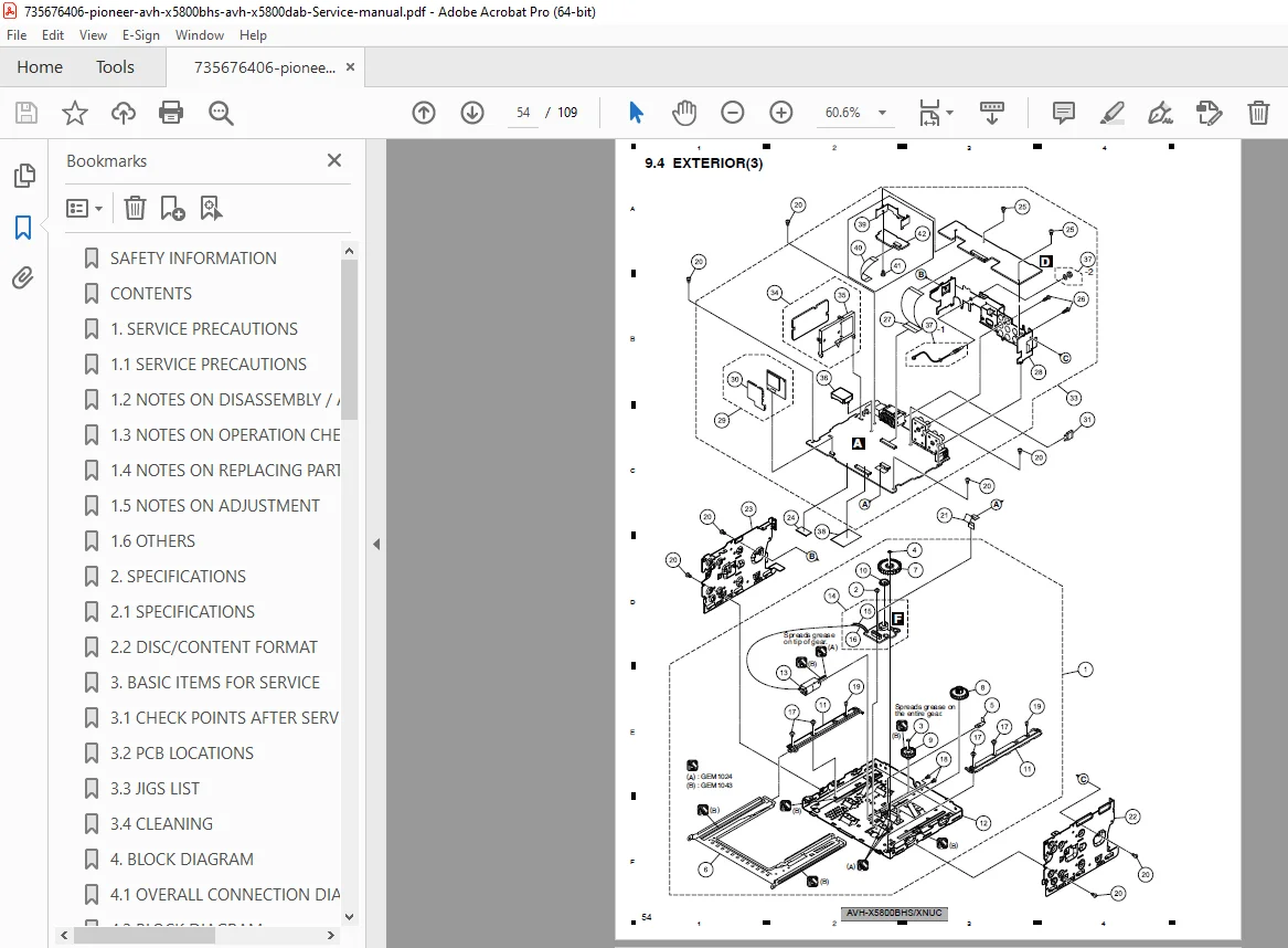
9.4 Exterior (3):
- Additional external components
- Cable assemblies
- Mechanical linkages
9.5 DVD Mechanism Module (1):
- Disc transport mechanism
- Motor assemblies
- Pickup unit components
9.6 DVD Mechanism Module (2):
- Additional mechanism parts
- Sensors and switches
- Loading mechanism details
Section 10: Schematic Diagrams
Complete circuit schematics for all subsystems:
10.1 Mother PCB (Vehicle IF) – Automotive interface circuits 10.2 Mother PCB (PWR_OTHER) – Auxiliary power circuits 10.3 Mother PCB (2ch DC/DC) – Dual-channel voltage converter 10.4 Mother PCB (1ch DC/DC) – Single-channel voltage converter 10.5 Mother PCB (SYSCOM) – System communication circuits 10.6 Mother PCB (GERDA) – Audio processing section 10.7 Mother PCB (AVSEL) – Audio/video source selection 10.8 Mother PCB (OPAL) – Video processing circuits 10.9 Mother PCB (PWR-IC) – Power management IC 10.10 Mother PCB (PWR-TUN) – Tuner power supply 10.11 Mother PCB (HD/DAB) – HD Radio/DAB tuner circuits 10.12 Mother PCB (LITHIO) – Lithium backup circuits 10.13 Mother PCB (PWR_USB) – USB power management 10.14 Mother PCB (LS2.5_IF) – DVD mechanism interface 10.15 Mother PCB (EXT_I/F) – External input/output interface 10.16 Mother PCB (BT) – Bluetooth module circuits 10.17 Service Unit (Monitor) (PCB I/F) – Display interface 10.18 Service Unit (Monitor) (LED BL) – LED backlight driver 10.19 Service Unit (Monitor) (LCD PW) – LCD power supply 10.20 Service Unit (Monitor) (LCD I/F) – LCD interface 10.21 DVD Core Unit – Disc playback processor 10.22 Interface PCB – External connector board 10.23 Service Unit (Keyboard) – Front panel controls 10.24 PCB Unit (Service) – Service/diagnostic circuits 10.25 Waveforms – Expected signal waveforms at test points
Section 11: PCB Connection Diagram
11.1 Mother PCB – Main board connector pinouts 11.2 Service Unit (Monitor) – Display unit connections 11.3 DVD Core Unit – Mechanism connections 11.4 Interface PCB – External I/O connections 11.5 Service Unit (Keyboard) – Control panel connections 11.6 PCB Unit (Service) – Auxiliary board connections
Section 12: Electrical Parts List
- Complete component listings for all PCBs
- Part numbers and specifications
- Semiconductor device codes
- Capacitor and resistor values
- Connector part numbers
- Ordering information
Key Service Features
Comprehensive Troubleshooting:
- Error code database with solutions
- Flowchart-based diagnostic procedures
- Component-level fault isolation
- Measurement points and expected values
Laser Safety Compliance:
- IEC 60825-1:2007 safety standards
- Class 1/Class 1M laser product classification
- Service technician safety instructions
- Laser diode characteristics and caution notices
- Q1103 (DVD laser driver) and Q1104 (CD laser driver) safety warnings
Professional Calibration:
- Touch panel multi-point calibration
- Display flicker adjustment procedures
- Servo adjustment techniques
- Audio output level settings
Module Integration:
- Bluetooth pairing and diagnostics
- HD Radio/DAB tuner alignment
- USB interface troubleshooting
- Camera input configuration
Professional Applications
This service manual is essential for:
- Car Audio Installation Technicians performing warranty repairs
- Mobile Electronics Specialists servicing Pioneer AV receivers
- Automotive Service Centers with electronics departments
- Consumer Electronics Repair Shops specializing in car audio
- Marine Electronics Installers (for applicable installations)
- Technical Training Centers educating automotive electronics technicians
- Pioneer Authorized Service Centers worldwide
File Details
- Manual Name: AVH-X5800BHS/XNUC DVD RDS AV Receiver Service Manual
- Models Covered: AVH-X5800BHS/XNUC, AVH-X5800DAB/XNEU5, AVH-X5850TV/XNRD
- Order Number: CRT5819
- Publication Date: November 2015
- Companion Manual: CRT5651 (CX-3311 LS2.5 Mechanism Module)
- Manual Quality: Factory original PDF – Excellent quality with clear schematics
- Total Pages: 109 pages (plus companion manual reference)
- File Format: PDF (optimized, letter size, searchable)
- Language: English
- Publisher: Pioneer Corporation, Kawasaki-shi, Kanagawa, Japan
This service manual provides factory-level technical information essential for professional repair and maintenance of Pioneer’s advanced multimedia AV receivers, ensuring proper functionality and safety compliance.