Pioneer DV-350 DV-454 DVD Player Service Manual PDF Repair Guide Download
Original price was: $65.00.$20.95Current price is: $20.95.
Complete 106-page technical service manual for Pioneer DV-350-K, DV-350-S, DV-454-K, and DV-454-S DVD players. Comprehensive guide covering exploded views, circuit diagrams, parts lists, adjustment procedures, troubleshooting, mechanism repair, and complete specifications for professional technicians servicing these DVD video players.
Description
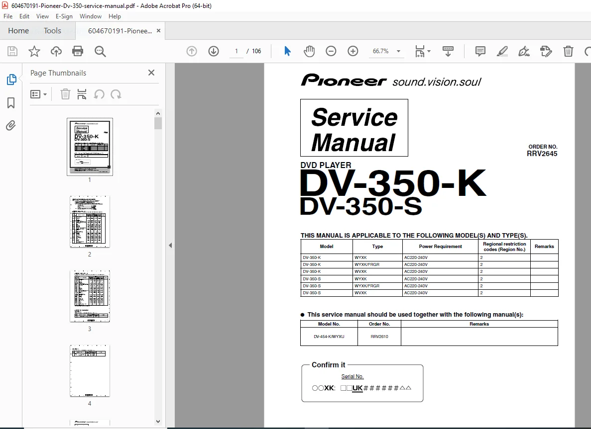
Pioneer DV-350 DV-454 DVD Player Service Manual PDF Repair Guide – PDF Download
DESCRIPTION:
This comprehensive Pioneer DV-350/DV-454 Service Manual provides complete technical documentation for servicing and repairing Pioneer DVD video players. This 106-page professional manual covers multiple model variants and is essential for electronics technicians, service centers, and audio/video repair professionals working on these popular Pioneer DVD players from the early 2000s era.
Models Covered
This technical service manual covers all variants of the Pioneer DV-350 and DV-454 DVD player series:
DV-350 Series (Black and Silver finishes):
- DV-350-K – Black finish models (WYXK, WYXK/FRGR, WVXK types)
- DV-350-S – Silver finish models (WYXK, WYXK/FRGR, WVXK types)
DV-454 Series (Black and Silver finishes):
- DV-454-K – Black finish models (WYXU, WYXU/FRGR, WVXU types)
- DV-454-S – Silver finish models (WYXU, WYXU/FRGR, WVXU types)
All models support DVD-Video, Video CD, standard CD, and MP3 file playback with Region 2 encoding.
Note: This manual (RRV2645) should be used in conjunction with manual RRV2610 for complete service information on all models.
System Specifications
General Features:
- Disc formats: DVD-Video, Video CD, Audio CD, MP3 files
- Power requirements: AC 220-240V, 50/60 Hz (European/International version)
- Power consumption: 14W (operating), 0.3W (standby)
- Dimensions: 420mm (W) x 55mm (H) x 278mm (D) (16.5″ x 2.2″ x 10.9″)
- Weight: 2.5 kg (5.5 lbs)
- Operating temperature: +5°C to +35°C (41°F to 95°F)
- Operating humidity: 5% to 85% (non-condensing)
- Regional restriction code: Region 2
Digital Audio Characteristics:
- Frequency response: 4 Hz to 44 kHz (DVD fs: 96 kHz)
- S/N ratio: 118 dB
- Dynamic range: 101 dB
- Total harmonic distortion: 0.0016%
- Wow and flutter: Below measurement limit (0.001% W. PEAK or lower)
Audio Output (1 Stereo Pair):
- Output level: 200 mVrms (1 kHz, –20 dB)
- Number of channels: 2 (stereo)
- Jacks: RCA jacks (red/white)
Video Output:
- S-Video output:
- Y (luminance): 1 Vp-p (75Ω)
- C (color): 286 mVp-p (75Ω)
- Composite video output: Standard RCA jack
- Digital audio output: Coaxial/optical (model dependent)
Complete Manual Contents
Section 1: Specifications
- Complete technical specifications
- Electrical characteristics
- Audio and video performance parameters
- Physical dimensions and weight
- Environmental operating requirements
- Power consumption details
Section 2: Exploded Views and Parts List
- 2.1 Packing:
- Shipping carton assembly
- Protective packaging components
- Accessory pack contents
- 2.2 Exterior Section:
- Front panel assembly
- Top cover and chassis
- Rear panel connectors
- Control buttons and display
- External hardware and screws
- 2.3 Loading Mechanism ASSY:
- Disc tray assembly exploded view
- Loading motor and drive components
- Gear train and mechanical linkages
- Tray sensors and switches
- Individual part numbers and descriptions
- 2.4 Traverse Mechanism ASSY-S:
- Optical pickup unit (OPU) assembly
- Traverse motor and sled mechanism
- Focus and tracking actuators
- Spindle motor assembly
- Mechanical adjustment components
- Part numbers for all mechanism components
Section 3: Block Diagram and Schematic Diagram
- 3.1 Block Diagram:
- 3.1.1 Signal Route:
- RF signal path from optical pickup
- Servo control signal flow
- Audio/video processing chain
- Digital signal processing overview
- 3.1.2 Power Supply Block:
- AC input and rectification
- Voltage regulation circuits
- Multiple voltage rail distribution
- Standby power supply
- 3.1.3 Waveforms:
- Critical signal waveforms at test points
- Timing diagrams
- Servo control signals
- 3.1.1 Signal Route:
- 3.2 LOAB ASSY and Overall Wiring Diagram:
- Loader/Optical assembly board schematic
- Complete system interconnections
- Cable harness routing
- 3.3 FJMB ASSY 1/5 [Front End Block]:
- RF amplifier circuits
- Focus/tracking error signal generation
- Optical pickup interface
- 3.4 FJMB ASSY 2/5 [Back End Block]:
- Digital signal processing
- System control processor
- Memory circuits
- 3.5 FJMB ASSY 3/5 [Audio Block]:
- Digital-to-analog audio conversion
- Audio processing and filtering
- Output amplifier stages
- 3.6 FJMB ASSY 4/5 [Video Block]:
- Video decoder circuits
- Video signal processing
- S-Video and composite output drivers
- 3.7 FJMB ASSY 5/5 [FL Control Block]:
- Front panel controls
- Display driver circuits
- LED/VFD display interface
- 3.8 IRKY and PSWB ASSYs:
- Infrared remote receiver schematic
- Power switch board circuits
- Standby control
- 3.9 Power Supply Unit (VWR1352):
- Complete power supply schematic (version 1)
- Component values and ratings
- 3.10 Power Supply Unit (VWR1354):
- Complete power supply schematic (version 2)
- Alternative power supply configuration
- 3.11 SCRB ASSY:
- System control board schematic
- Microprocessor interface circuits
Section 4: PCB Connection Diagram
- 4.1 LOAB ASSY:
- Connector locations and pinouts
- Inter-board connection details
- 4.2 FJMB ASSY:
- Main board connector arrangement
- Pin assignments for all connectors
- Signal descriptions
- 4.3 IRKY and PSWB ASSYs:
- Remote receiver connections
- Power switch board pinouts
- 4.4 Power Supply Unit (VWR1352):
- Input/output connector details
- Voltage rail distribution
- 4.5 Power Supply Unit (VWR1354):
- Alternative power supply connections
- Pin assignments
- 4.6 SCRB ASSY:
- System control board connections
- Interface specifications
Section 5: PCB Parts List
- Complete component listings for all PCBs
- Reference designators (R, C, IC, Q, D, etc.)
- Component values and ratings
- Part numbers for ordering replacements
- Safety-critical component identification (marked with ⚠️)
- NSP (Non-Stock Parts) notation
- Resistor color code and ordering information
- Component substitution guidelines
Section 6: Adjustment
- 6.1 Adjustment Items and Location:
- Overview of all adjustable parameters
- Location of adjustment points on PCBs
- Variable resistor (VR) locations
- 6.2 Jigs and Measuring Instruments:
- Required test equipment
- Special adjustment jigs
- Standard test discs needed
- Oscilloscope requirements
- Multimeter specifications
- 6.3 Necessary Adjustment Points:
- Critical adjustments after repair
- Alignment procedures
- Calibration requirements
- 6.4 Test Mode:
- Entering service/test mode
- Test mode navigation
- Available test functions
- Diagnostic readouts
- 6.5 Mechanism Adjustment:
- Optical pickup adjustments:
- Focus gain adjustment
- Tracking gain adjustment
- Focus offset calibration
- Tracking offset calibration
- Spindle motor speed adjustment
- Tray loading mechanism alignment
- Limit switch positioning
- Mechanical tolerances and measurements
- Optical pickup adjustments:
Section 7: General Information
- 7.1 Diagnosis:
- 7.1.1 Test Mode:
- Detailed test mode operation
- Function test procedures
- Self-diagnostic routines
- Signal level measurements
- Servo parameter checking
- 7.1.2 Display of Mechanism Error History:
- Error code retrieval
- Error log interpretation
- Mechanism fault history
- Diagnostic trouble codes (DTCs)
- 7.1.3 Test Points Location & Waveforms:
- PCB test point maps
- Expected waveforms at critical points
- Voltage measurements
- Signal timing diagrams
- Oscilloscope probe points
- 7.1.4 Troubleshooting:
- Systematic troubleshooting procedures
- Symptom-based diagnosis
- Component testing methods
- Signal tracing techniques
- Common failure modes and solutions
- 7.1.5 Sequence After Power On:
- Boot-up sequence description
- Initialization routines
- Self-test procedures
- Normal startup behavior
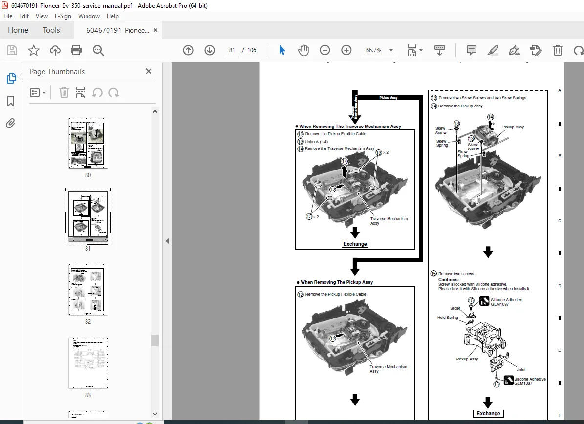
- 7.1.6 Disassembly:
- Step-by-step disassembly procedures
- Screw locations and types
- PCB removal sequences
- Mechanism extraction procedures
- Cable disconnection order
- Reassembly notes and precautions
- 7.1.1 Test Mode:
- 7.2 IC:
- Integrated circuit pin assignments
- IC function descriptions
- Voltage specifications
- Signal descriptions for major ICs
- Processor specifications
- 7.3 Cleaning:
- Optical pickup lens cleaning procedures
- Approved cleaning solutions
- Disc loading mechanism cleaning
- Contact cleaning methods
- Preventive maintenance cleaning
Section 8: Panel Facilities
- Front panel layout and functions
- Rear panel connector descriptions
- Remote control functions
- Display indicators and meanings
- Button operation details
Key Features of This Service Manual
✓ Official Pioneer documentation – Factory authorized service information ✓ 106 comprehensive pages with detailed diagrams and procedures ✓ Multiple model coverage – DV-350 and DV-454 series (8 variants total) ✓ Complete circuit schematics for all PCB assemblies ✓ Exploded view diagrams for mechanical components ✓ Detailed parts lists with part numbers for ordering ✓ Adjustment procedures with test mode instructions ✓ Troubleshooting guides with error code interpretation ✓ Waveform diagrams at critical test points ✓ PCB connection diagrams with pinout information ✓ Power supply schematics for multiple versions ✓ Complete specifications for all models
Who Should Use This Manual
This Pioneer DV-350/DV-454 service manual is designed for:
- Professional electronics technicians
- Audio/video equipment repair shops
- Pioneer authorized service centers
- Consumer electronics repair specialists
- Technical schools and training programs
- Hobbyist electronics enthusiasts with repair experience
- Home theater installation professionals
Important Service Notes
Safety Critical Components:
- Parts marked with ⚠️ symbol are safety-critical
- Always replace with identical specification parts
- Maintain original lead dress and component spacing
- Use only specified safety-approved replacement parts
Regional Coding:
- All covered models are Region 2 (Europe/Japan/Middle East)
- Regional coding is firmware-based
- Do not attempt to modify regional restrictions
Power Supply Variants:
- Two power supply versions exist (VWR1352 and VWR1354)
- Identify correct version before ordering parts
- Not interchangeable without corresponding modifications
Contrast Table:
- DV-350-K and DV-454-K are structurally similar
- Refer to contrast table for specific differences
- Some PCB assemblies differ between variants (LOAB, FJMB)
Common Repair Procedures Covered
- Disc reading problems – Optical pickup alignment and cleaning
- Tray loading issues – Mechanism adjustment and motor replacement
- No power/standby issues – Power supply troubleshooting and repair
- Audio/video output problems – Signal path diagnosis and component replacement
- Display malfunctions – Front panel board repair
- Remote control problems – IR receiver testing and replacement
- Servo errors – Focus/tracking adjustment and calibration
- Disc spinning problems – Spindle motor and driver circuit repair
Test Equipment Required
- Oscilloscope (dual trace recommended)
- Digital multimeter
- DVD test disc
- Video CD test disc
- Audio CD test disc
- RF signal level meter (optional)
- Pioneer service jigs (where specified)
Manual Quality and Format
- Format: Professional PDF document
- Pages: 106 pages of comprehensive technical content
- Graphics: High-quality schematics, diagrams, exploded views
- Organization: Logical section structure with detailed table of contents
- File size: 6.3 MB – Detailed schematics and illustrations
- Publisher: Pioneer Corporation – Official factory documentation
- Print-friendly: Suitable for printing individual sections
This Pioneer DV-350/DV-454 Service Manual PDF provides complete technical documentation essential for professional service and repair of these popular Pioneer DVD players from the early 2000s era.
FILE DETAILS:
| Manual Type | Technical Service Manual |
|---|---|
| Models Covered | DV-350-K (WYXK, WYXK/FRGR, WVXK)<br>DV-350-S (WYXK, WYXK/FRGR, WVXK)<br>DV-454-K (WYXU, WYXU/FRGR, WVXU)<br>DV-454-S (WYXU, WYXU/FRGR, WVXU) |
| Year | 2002 Edition (July 2002) |
| Pages | 106 pages |
| PDF Quality | Excellent – Original manufacturer document |
| File Size | 6.3 MB |
| Language | English |
| Publisher | Pioneer Corporation |
| Order Number | RRV2645 (DV-350), RRV2610 (DV-454) |
| Region Code | Region 2 (Europe/Japan/Middle East) |
| Power | AC 220-240V, 50/60Hz |