Radiometer ABL90 FLEX PLUS Blood Gas Analyzer Service Manual PDF
Original price was: $95.00.$30.95Current price is: $30.95.
Official Radiometer ABL90 FLEX and FLEX PLUS blood gas analyzer service manual (Document 994667, December 2016). Comprehensive 290-page technical guide covering troubleshooting, checkout/adjustment procedures, component replacement, periodic service, module descriptions, spare parts, wiring diagrams. Essential for biomedical technicians servicing clinical laboratory blood gas analyzers. Includes sensor calibration, fluid path diagnostics, software installation, electrolyte systems, oximetry modules.
Description
Radiometer ABL90 FLEX PLUS Blood Gas Analyzer Service Manual 994667 Dec 2016 PDF DOWNLOAD
DESCRIPTION
This is the official Radiometer ABL90 FLEX and ABL90 FLEX PLUS Blood Gas Analyzer Service Manual (Document Number 994667, Revision December 2016), providing complete service and repair procedures for these advanced point-of-care blood gas analysis systems manufactured by Radiometer Medical ApS.
Models Covered
- ABL90 FLEX (Model 393-090R)
- ABL90 FLEX PLUS (Model 393-092R)
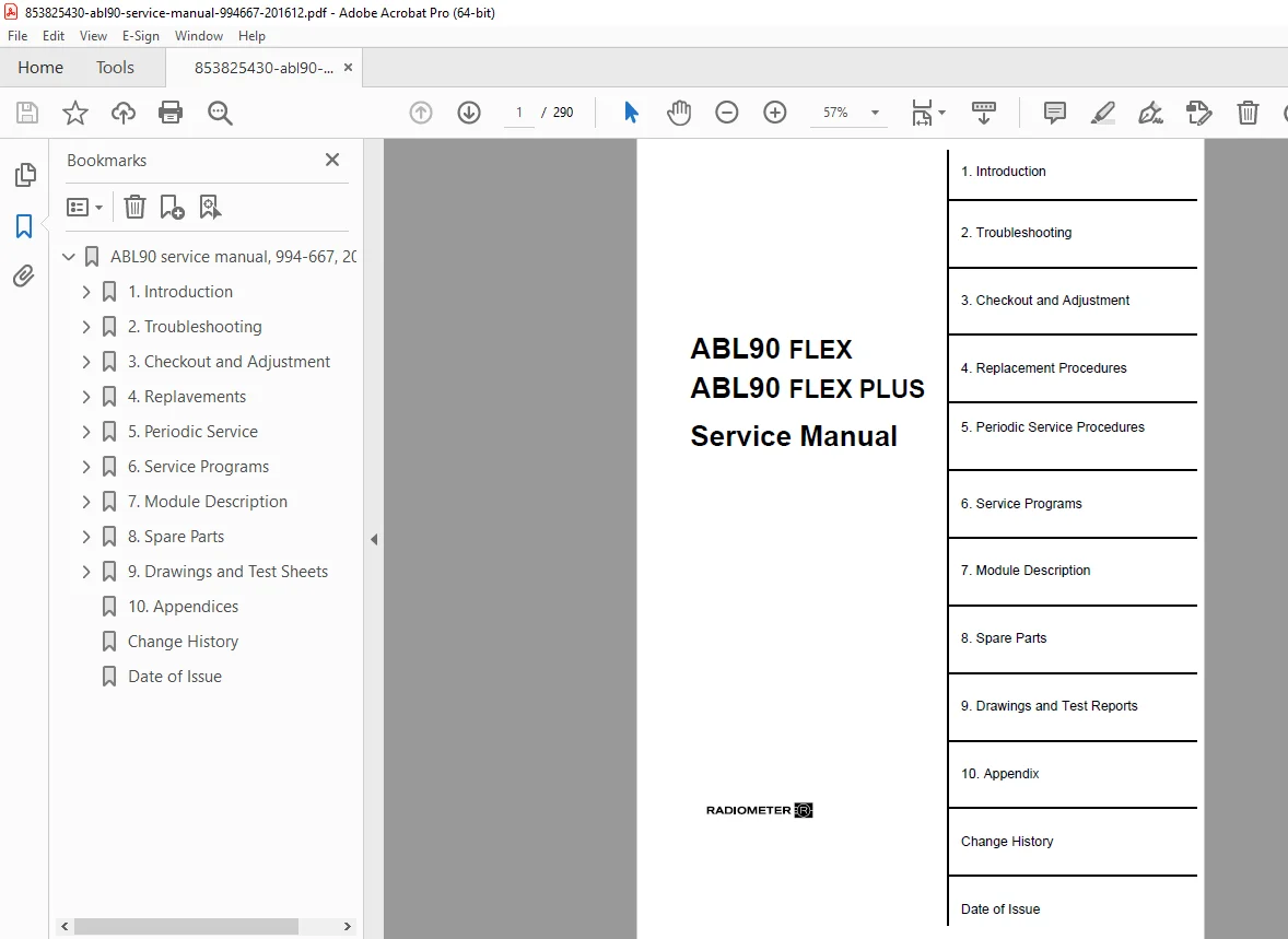
Complete Manual Structure (290 Pages)
Chapter 1 – Introduction (Pages 1-1 to 1-10):
Disclaimer and Service Policy:
- System performance requirements
- Radiometer warranty conditions
- Microsoft Windows Embedded and Sybase SQL Anywhere software licensing
- End User License Agreement (EULA) compliance
- Third-party software restrictions
- Liability disclaimers
Service Policy Requirements:
- Advanced configuration restrictions (IT Specialist only)
- Software installation policies – only Radiometer-approved software permitted
- Windows XPE hotfix procedures
- Windows XPE Firewall configuration (Port 6502 for NetOp remote access)
- ESD (Electrostatic Discharge) protection requirements
- Repair level limitations:
- Electronics: Field repair not permitted – SMT technology requires factory service
- Wet Section: Component-level repair allowed
- Trade-in arrangement for modules marked with “*”
- Blood safety and disinfectant handling warnings
- Laser safety (Class 1 Laser Product per IEC 60825-1)
- Calibration and measurement requirements (fully assembled only)
Test Equipment and Tools:
- 3½ digit DMM (Digital Multimeter)
- USB keyboard or PS/2 keyboard
- USB sticks (≥2 GB for software installation and data dumps)
- Sensor Simulator (Part# 903-603)
- Tubing Tweezers (920-627)
- Flush Device (905-918)
- Torx Screwdrivers (TX6, TX8, TX10, TX20)
- Short TX10 Screwdriver for manual sensor unit operation
- PZ0 Screwdriver for contact probe array
- 4mm Hex Key for sensor module alignment
- Sensor Module Adjustment Tool (920-757)
- Magnifying Glass (920-751)
- Spring Wind Tool (920-774)
- Molykote PG75 Grease (991-187)
- Software installation media:
- RXPE iso files (933-337)
- RWES7 iso files (933-367)
- Analyzer Application Software V3.1 MR8 (933-366)
- BIOS Update Tool (933-350)
- Certificates and licenses (RXPE, RWES7, Sybase16, NetOp Guest)
Installation ID:
- Serial number syntax and location
- Analyzer ID PCB chip functionality
- Traceability and service logging
- Future options association
Chapter 2 – Troubleshooting (Pages 2-1 to 2-48+):
Comprehensive Message Codes: Over 100+ error messages with detailed service actions, including:
Critical System Messages:
- Message #1: Inconsistent software versions
- Message #963, #964: Leak current detected
- Message #1169: Unable to pump solution
- Message #1184: Leak detected
- Sensor calibration failures
- Temperature regulation errors
Quality Control Messages:
- Messages #83-94: Reference range violations, critical limits
- Messages #89-90: QC values above/below control range
- Messages #201-206: Westgard Rule violations (statistical quality control)
- 1.2s, 1.3s, 2.2s, R.4s, 4.1s, 10.x rules
- Messages #207-212: Schedule reminders and status alerts
LIS/HIS Communication Errors:
- Messages #117-167: Connection configuration, packet send/receive failures
- Protocol errors and communication traces
- High-level packet generation/parsing issues
Calibration and Measurement Errors:
- Messages #375-379: Calibration status, drift, sensitivity, unstable response
- Messages #521-523: Calibration errors and drift out of range
- Messages #529-537: Liquid sensor calibration failures (LS1, LS2, LS3)
- Messages #581-584: OXI spectrum mismatch, tHb calibration issues
Sample Detection and Processing:
- Message #331: No sample detected during aspiration
- Message #521: Inhomogeneous sample (air bubbles)
- Message #593: Insufficient sample volume
- Messages #290-293: SHb warnings, turbidity, HbF compensation
Temperature and Transport:
- Message #357: Barometer temperature error
- Message #508: Liquid transport error during rinse
- Message #512: Temperature out of range during measurement
Troubleshooting Guide (Appendix 1):
- Systematic decision trees for common issues
- Leak current detection procedures
- Pump solution failure diagnosis
- Leak detection protocols
- Individual sensor troubleshooting
Status Codes (Page 2-48):
- Analyzer status code reference
- Module-specific status indicators
Chapter 3 – Checkout and Adjustment:
- Sensor calibration procedures
- Contact probe alignment
- Fluid path verification
- Temperature regulation checks
- Optical system adjustments
- Pump motor function tests
- Actuator and valve operations
- Liquid sensor calibration
Chapter 4 – Replacement Procedures:
- Module removal and installation
- Sensor cassette replacement
- PCB replacement procedures:
- Wet Section Control PCB
- Sensor Interface PCB
- Analyzer Control PCB
- Hemolyzer PCB
- CPU Unit
- Pump motor replacement
- Actuator replacement
- Flow selector service
- Valve replacement
- Tubing replacement
- Liquid sensor replacement (LS1, LS2, LS3)
- Contact probe array service
- Inlet module gasket replacement
- Barcode scanner replacement
Chapter 5 – Periodic Service Procedures:
- Daily maintenance tasks
- Weekly service requirements
- Monthly preventive maintenance
- Quarterly inspection schedules
- Annual comprehensive service
- Software backup procedures
- Database maintenance
- Cleaning and disinfection protocols
Chapter 6 – Service Programs:
- Service mode access procedures
- Diagnostic test programs
- Sensor check routines
- Motor function tests
- Isolation tests
- Temperature verification programs
- OXI Complete Test procedures
- Liquid sensor tests
- Pump calibration programs
Chapter 7 – Module Description:
- Wet Section Modules:
- Sensor Cassette Bay Unit
- Hemolyzer (oximetry)
- Spectrometer
- Pump assemblies
- Actuator mechanism
- Flow Selector
- Valve assemblies
- Electronic Modules:
- CPU Unit (UIM2743, UIM910, UIM945 hardware)
- Wet Section Control PCB
- Sensor Interface PCB
- Analyzer Control PCB
- Hemolyzer PCB
- Input/Output:
- Printer Unit
- Barcode Scanner
- Inlet Module
- Display and touch screen
- Software Components:
- Windows Embedded (RXPE/RWES7)
- Analyzer Application Software
- Sybase SQL Anywhere database
- Communication protocols
- NetOp remote access
Chapter 8 – Spare Parts:
- Complete parts catalog with part numbers
- Module assemblies
- Electronic components (trade-in modules marked “*”)
- Mechanical components
- Tubing and gaskets
- Sensors and electrodes
- Solution packs
- Calibration solutions
- QC materials
- Consumables
- Accessories
Chapter 9 – Drawings and Test Reports:
- Exploded view diagrams
- Assembly drawings
- Fluid path schematics
- Electrical schematics
- Connector pinouts
- Module layouts
- Test report templates
- Calibration record forms
Chapter 10 – Appendix:
- Appendix 1: Troubleshooting Guide
- Decision tree flowcharts
- Leak detection procedures
- Fluid transport diagnostics
- Sensor issue resolution
- Software License Agreements
- Safety data sheets
- Conversion tables
- Technical specifications
- Maintenance logs
Key Technical Systems Covered
Blood Gas Parameters:
- pH
- pCO2 (Carbon Dioxide)
- pO2 (Oxygen)
- Electrolytes: Na+, K+, Ca2+, Cl-
- Metabolites: Glucose, Lactate
- cCa2+ (Ionized Calcium) with pH 7.4 correction
Oximetry Parameters (OXI Module):
- tHb (Total Hemoglobin)
- SO2 (Oxygen Saturation)
- O2Hb (Oxyhemoglobin)
- COHb (Carboxyhemoglobin)
- MetHb (Methemoglobin)
- HHb (Deoxyhemoglobin)
- FHbF (Fetal Hemoglobin)
- Bilirubin compensation
- Turbidity detection
Calculated Parameters:
- Base Excess
- Bicarbonate
- Hematocrit (from tHb)
- Various derived parameters
Calibration Systems:
- Multi-point calibration with drift monitoring
- Automatic calibration scheduling
- Calibration status monitoring
- Sensitivity checks
- Drift 1 and Drift 2 verification
Quality Control:
- Westgard Rules implementation
- Multi-level QC (typically 3 levels)
- Statistical process control
- Trend analysis
- QC expiration monitoring
Software and Communication
Operating System:
- Windows XPE (Embedded)
- Windows Embedded Standard 7 (RWES7) upgrade path
- Sybase SQL Anywhere database
Connectivity:
- LIS/HIS interface (ASTM, HL7, custom protocols)
- TCP/IP networking
- RS-232 serial communication
- USB connectivity
- NetOp remote access capability
- Network backup functionality
Data Management:
- Patient result storage
- QC data archiving
- Calibration history
- Activity logging
- Automatic/manual backup
- Database maintenance tools
Safety and Regulatory Compliance
⚠ Bloodborne Pathogen Safety – Protective gear required
⚠ Chemical Hazard Warnings – Disinfectant handling protocols
⚠ ESD Protection – Required for all electronic components
⚠ Laser Safety – Class 1 Laser Product (IEC 60825-1)
⚠ Electrical Safety – Proper grounding and isolation
⚠ Software Security – Firewall enabled, limited port access
⚠ Warranty Compliance – Only authorized parts and procedures
Who Should Use This Manual
- Biomedical Equipment Technicians (BMET) – hospital clinical engineering
- Clinical Laboratory Service Engineers – specialized medical equipment repair
- Radiometer Authorized Service Personnel – factory-trained technicians
- Field Service Engineers – on-site analyzer maintenance
- Hospital Engineering Departments – in-house service capabilities
- Independent Service Organizations (ISO) – third-party service providers
- Point-of-Care Coordinators – POC testing program management
- Clinical Chemistry Supervisors – understanding service requirements
Applications
ABL90 FLEX analyzers are used in:
- Hospital emergency departments
- Intensive care units (ICU/CCU)
- Operating rooms
- Clinical laboratories
- Neonatal units
- Cardiac catheterization labs
- Blood banks
- Research facilities
- Veterinary hospitals
File Details
| Specification | Details |
|---|---|
| Manual Title | ABL90 FLEX / ABL90 FLEX PLUS Service Manual |
| Manufacturer | Radiometer Medical ApS |
| Document Number | 994667 |
| Revision Date | December 2016 (201612) |
| Models Covered | ABL90 FLEX (393-090R), ABL90 FLEX PLUS (393-092R) |
| Number of Pages | 290 |
| PDF Quality | Excellent – Professional factory manual |
| Author | Mogens H. Thomasen |
| Creation Date | February 2015 (updated December 2016) |
| Language | English |
| Standards | IEC 60825-1 (Laser Safety) |
This comprehensive service manual is essential for anyone responsible for maintaining, troubleshooting, or repairing Radiometer ABL90 FLEX blood gas analyzers. With detailed error code diagnostics, step-by-step replacement procedures, calibration protocols, and complete module descriptions, this manual provides everything needed to keep these critical point-of-care analyzers operating reliably in clinical settings.
FILE DETAILS TABLE
| Specification | Details |
|---|---|
| Manual Name | ABL90 FLEX / ABL90 FLEX PLUS Service Manual |
| Manufacturer | Radiometer Medical ApS |
| Equipment Type | Blood Gas Analyzer (Point-of-Care) |
| Models | ABL90 FLEX, ABL90 FLEX PLUS |
| Model Numbers | 393-090R (FLEX), 393-092R (FLEX PLUS) |
| Document Number | 994667 |
| Revision | December 2016 (201612) |
| Number of Pages | 290 |
| PDF Quality | Excellent – Professional factory technical manual |
| Language | English |
| Manual Type | Complete Service Manual |