RAYMOND 8300, 8400, and 8500 Pallet Trucks and Model 8600 Tow Tractor Maintenance Manual – PDF DOWNLOAD
Original price was: $78.00.$27.95Current price is: $27.95.
RAYMOND 8300, 8400, and 8500 Pallet Trucks and Model 8600 Tow Tractor Maintenance Manual – PDF DOWNLOAD
Description
RAYMOND 8300, 8400, and 8500 Pallet Trucks and Model 8600 Tow Tractor Maintenance Manual – PDF DOWNLOAD
FILE DETAILS:
RAYMOND 8300 8400 and 8500 Pallet Trucks and Model 8600 Tow Tractor Maintenance Manual – PDF DOWNLOAD
Language : English
Pages : 331
Downloadable : Yes
File Type : PDF
Size: 13.2 MB
DESCRIPTION:
RAYMOND 8300 8400 and 8500 Pallet Trucks and Model 8600 Tow Tractor Maintenance Manual – PDF DOWNLOAD
Manual Design
- Look up the component name in the list of Component Procedures.
- Find the component in the Component Locator Photographs.
- Look up the component name in the Index.
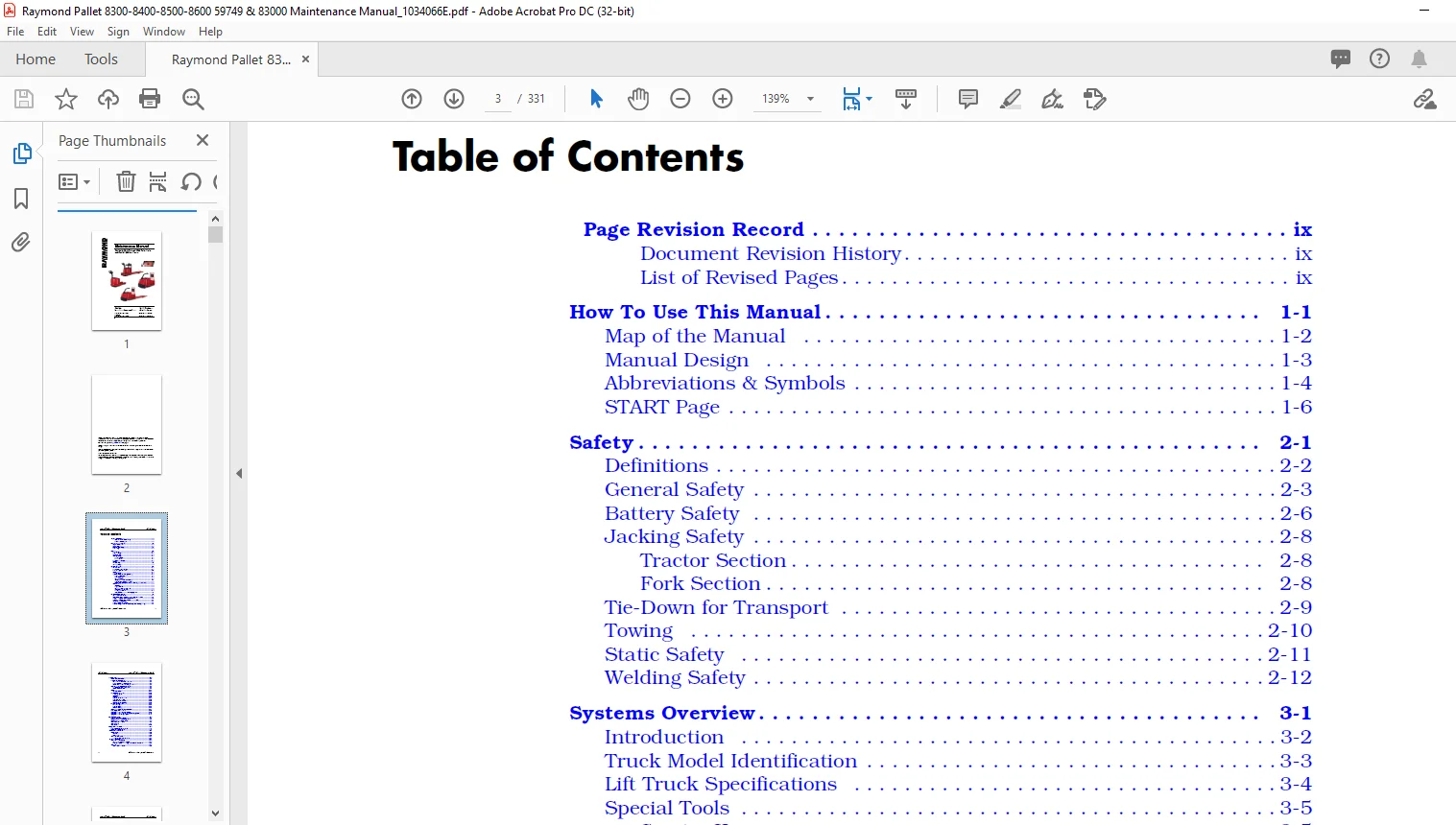
TABLE OF CONTENTS:
RAYMOND 8300 8400 and 8500 Pallet Trucks and Model 8600 Tow Tractor Maintenance Manual – PDF DOWNLOAD
Page Revision Record ix
Document Revision History ix
List of Revised Pages ix
How To Use This Manual 1-1
Map of the Manual 1-2
Manual Design 1-3
Abbreviations & Symbols 1-4
START Page 1-6
Safety 2-1
Definitions 2-2
General Safety 2-3
Battery Safety 2-6
Jacking Safety 2-8
Tractor Section 2-8
Fork Section 2-8
Tie-Down for Transport 2-9
Towing 2-10
Static Safety 2-11
Welding Safety 2-12
Systems Overview 3-1
Introduction 3-2
Truck Model Identification 3-3
Lift Truck Specifications 3-4
Special Tools 3-5
Service Key 3-5
Operator Display and Programming 3-6
Special Truck Mode 3-6
Hour Meter (H) 3-6
Error Codes (E) 3-6
Changing Truck Parameters (P) 3-7
Service Input/Output Displays 3-13
Digital Inputs/Outputs from Traction Amplifier and VM 3-13
FlashWare 3-16
Overview 3-16
Requirements 3-16
Installing FlashWare on PC 3-16
Connecting PC to Truck 3-16
Starting FlashWare 3-16
Configuration and Truck Setup Options 3-17
Scheduled Maintenance 4-1
Maintenance Guidelines 4-2
Initial 90 Day/250 Deadman Hours (HD) Maintenance 4-3
Every 180 Days or 500 Deadman Hours 4-4
Every 360 Days or 2000 Deadman Hours (HD) 4-6
Contactor Tip Inspection 4-7
Grease Fittings (All Models) 4-8
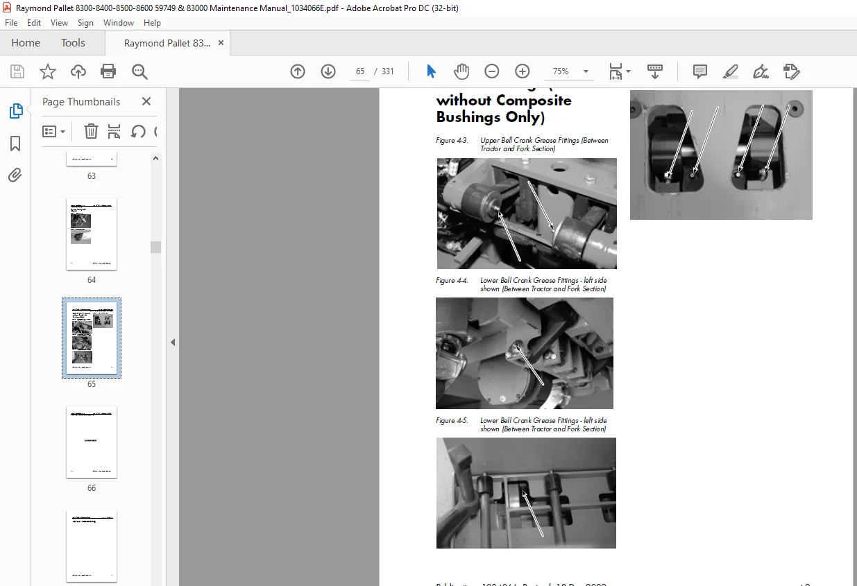
Grease Fittings (Trucks without Composite Bushings Only) 4-9
Table of Contents Raymond® Pallet Truck Maintenance Manual
ii Publication: 1034066 Revised: 18 Dec 2009
Troubleshooting 5-1
How to Use This Section 5-2
Troubleshooting Flowcharts 5-3
TS1: START TROUBLESHOOTING 5-3
GEN1: General Troubleshooting 5-4
END1: End of Troubleshooting Procedure 5-5
Electrical Troubleshooting Guidelines 5-6
Troubleshooting the CAN Bus. 5-6
Shorts to Frame Test 5-8
Fuses 5-11
Test/Inspection 5-11
DC Electric Motor Tests 5-12
DC Motor Types 5-12
Inspection 5-12
Service 5-12
Open Circuit Motor Test 5-14
Grounded Motor Test 5-15
Short-Circuited Armature 5-15
Short-Circuited Winding 5-15
AC Electric Motor Tests 5-16
AC Motor Type 5-16
Open Winding 5-16
Shorted Winding. 5-16
Hydraulic Troubleshooting Guidelines 5-17
List of Symptom Tables 5-18
Symptom Tables: Lift/Lower System 5-19
Symptom Tables: Travel (Forward/Reverse) System 5-22
Symptom Tables: Wiring System 5-30
Messages and Codes 6-1
List of Messages and Codes 6-2
Traction Amplifier LED Diagnostics 6-3
Traction Amplifier Flash Codes 6-4
Caution and Error Codes 6-6
Caution Codes 6-7
Error Codes 6-19
Component Procedures 7-1
List of Component Procedures 7-2
Component Locator Photos 7-5
Finish and Accessories 7-9
Tractor Cover 7-10
Removal 7-10
Installation 7-10
Cushioned Floor Mats 7-11
Gluing Cushioned Floor Mats 7-11
Steering and Controls. 7-13
Control Handle Assembly 7-14
Spring-Loaded Handle Design. 7-14
Fixed-Position Handle Design – Models 8500 and 8600 7-16
Control Handle 7-17
Control Head Removal 7-19
Raymond® Pallet Truck Maintenance Manual Table of Contents
Publication: 1034066 Revised: 18 Dec 2009 iii
Changing Horn Button/Switch 7-19
Changing Lift/Lower Button Assembly 7-20
Changing the Push Button 7-20
Changing the Coast/Side Button Controls 7-21
Changing the Side Button Control and Spring. 7-21
Drive and Brake 7-23
Drive Unit 7-24
Removal 7-24
Steering Bearing 7-25
Gear Assembly 7-28
Checking the Gears. 7-29
Adjusting Tooth Pattern of Drive Unit 7-29
Installation 7-30
Drive Housing Lubrication 7-32
Gear Oil Level 7-32
Changing Gear Oil 7-32
Drive Wheel 7-33
Removal 7-33
Cushion Tire Replacement 7-33
Caster Adjustment 7-35
Casters (Torsion) 7-36
Caster Removal. 7-36
Wheel Replacement. 7-36
Caster Assembly 7-36
Caster Installation 7-37
Casters (Spring-Loaded) 7-38
Removal 7-38
Wheel Replacement. 7-38
Caster Disassembly 7-39
Caster Assembly 7-40
Wheel Installation 7-40
Caster Installation 7-40
Brake 7-42
Spring-Loaded Handle 7-42
Fixed-Position Handle – Models 8500 and 8600. 7-44
Electrical Components 7-45
Battery 7-46
With Battery Gates and Rollers (Optional) 7-46
Battery Gates (Optional) 7-46
Battery Rollers (Optional) 7-46
Without Battery Gates and Rollers 7-46
Battery Exterior Cleaning 7-47
Testing Charging and Maintenance 7-48
Maintenance-Free Batteries 7-48
Storage 7-48
Power Cables 7-49
Power Cable Repair 7-49
Wiring Harness 7-51
Terminology 7-51
Inspection. 7-51
Repair. 7-51
Soldering Procedures 7-52
Table of Contents Raymond® Pallet Truck Maintenance Manual
iv Publication: 1034066 Revised: 18 Dec 2009
AMP Harness/Traction Amplifier Connector 7-53
Connector Components 7-53
Disassembly (Contact Removal) 7-53
Contact Insertion 7-53
Assembly 7-54
Testing 7-55
Switches (General) 7-56
Test/Inspection 7-56
Key Switch (SW1) 7-57
Inspection 7-57
Removal 7-57
Installation 7-57
Brake (Deadman) Switch (SW2) 7-58
Adjustment 7-58
Removal 7-58
Installation 7-59
Lift-Limit Switch (SW8) 7-60
Adjustment 7-60
Grab Rail Switches 7-61
Model 8400 Only 7-61
Removal 7-61
Installation 7-61
Load Backrest Switches 7-62
Model 8500 Only (Optional) 7-62
Removal 7-62
Installation 7-62
Hydraulic Solenoids 7-63
Removal (Lower Solenoid/Valve) 7-63
Removal (Lift Motor Solenoid) 7-63
Installation (Lower Solenoid/Valve). 7-63
Installation (Lift Motor Solenoid) 7-63
Coast ™ Solenoid 7-64
Model 8400 (Optional) 7-64
Coast Solenoid Switch/Spring 7-67
Coast Canister 7-67
Horn 7-69
Removal 7-69
Installation 7-69
Traction Amplifier 7-70
Cleaning. 7-70
Removal 7-70
Installation 7-71
Programming 7-71
Contactors 7-72
Main Contactor 7-72
Motors General 7-75
Terminal Nuts 7-75
Traction Motor 7-76
Removal 7-76
Installation 7-77
Raymond® Pallet Truck Maintenance Manual Table of Contents
Publication: 1034066 Revised: 18 Dec 2009 v
Lift Motor 7-79
General Data 7-79
Removal 7-79
Installation 7-79
Hydraulic Components 7-81
Hydraulic Components 7-82
General Guidelines 7-82
Hydraulic Fluid 7-83
Checking Hydraulic Fluid Level. 7-83
Changing Hydraulic Fluid 7-83
Hydraulic Unit 7-84
Removal 7-84
Installation 7-84
Hydraulic Reservoir 7-85
Removal 7-85
Installation 7-85
Filter Screen and Suction Tube 7-86
Removal 7-86
Installation 7-86
Hydraulic Pump 7-87
Removal 7-87
Installation 7-87
Adjusting Hydraulic Pump Relief Valve Pressure 7-88
Checking Relief Valve Setting 7-88
Alternate Method Using Rated Load on Pallets: 7-88
Removal 7-89
Installation 7-89
Check Valve 7-89
Hydraulic Ram 7-90
Inspection. 7-90
Removal 7-90
Installation 7-92
Hydraulic Cylinder Seals. 7-93
Mast 7-97
Top Linkage Subassembly 7-98
Removal 7-98
Pull Rod Subassembly 7-101
Removal 7-101
Installation 7-102
Load Wheels 7-104
Single Load Wheels – Models 8300 8400 and 8500 7-104
Tandem Load Wheels – Models 8400 and 8500 7-104
Suspension Wheel – Model 8600 7-105
Pallet Entry Sliders 7-107
Replacement 7-107
Pallet Entry Rollers 7-108
Replacement 7-108
Fork Height Adjustment 7-109
Downstop Installation 7-110
Adjustment. 7-110
Pallet Entry/Exit Improvements 7-111
Table of Contents Raymond® Pallet Truck Maintenance Manual
vi Publication: 1034066 Revised: 18 Dec 2009
Options 7-113
Cold Storage Conditioning 7-114
Cold Storage Hydraulic Fluid 7-114
Theory of Operation 8-1
Definitions 8-2
Acceleration Rate 8-2
Brake (Deadman) Switch 8-2
Continuity 8-2
Controller Area Network (CAN) 8-2
Current Limiting. 8-2
Deceleration (Neutral Braking) 8-2
Emergency Reverse (Models 8300 and 8400). 8-2
Fault Codes 8-2
High Pedal Disable (HPD) 8-3
Open Circuit. 8-3
Overtemperature (Traction Amplifier) 8-3
Overvoltage Cutoff 8-3
PIN-Key Code 8-3
Pulse Width Modulation 8-3
Ramp Shape 8-3
Regenerative Braking 8-3
Sequencing Delay 8-3
Short Circuit or “Short” 8-4
Speed Limiting 8-4
Static Return to Off (SRO). 8-4
Thermal Cutback (Traction Amplifier) 8-4
Throttle Map. 8-5
Truck Off Delay (Keypad only). 8-5
Undertemperature 8-5
Undervoltage Cutoff 8-5
VM (Vehicle Manager) 8-5
Walking Speed 8-5
Traction System 8-6
Vehicle Manager (VM) 8-6
Traction Amplifier (TA) 8-6
Battery Plugged In 8-6
Key Switch ON and M1 Energized 8-6
Travel Request Tractor-First 8-7
Travel Request Forks-First. 8-7
Strip Curtain Bypass (Model 8400 only) 8-7
Emergency Reverse (Model 8300 and 8400) 8-7
Jog Mode 8-8
Coast Mode 8-8
Coast ™ (Model 8400 only) 8-8
Lift/Lower System 8-9
Lift 8-9
Lower 8-9
Pinout Matrix 8-10
Raymond® Pallet Truck Maintenance Manual Table of Contents
Publication: 1034066 Revised: 18 Dec 2009 vii
Appendix. A-1
Lubrication Equivalency Chart A-2
Thread Adhesives Sealants and Lubricants A-3
Component Specific Service/Torque Chart A-4
Torque Chart – Standard (Ferrous) A-7
Torque Chart – Standard (Brass) A-8
Torque Chart – Metric A-9
Torque Chart – Thread-Forming Screws A-10
Decimal Equivalent Chart A-11
Standard/Metric Conversions A-13
List of Electrical Symbols A-15
Schematics A-17
Electrical Schematics A-19
Power Distribution Diagram A-24
Hydraulic Schematic A-25
Index I-1
IMAGES PREVIEW OF THE MANUAL:
Questions? Email us: [email protected]
PLEASE NOTE:
- This is the SAME MANUAL used by the dealerships to diagnose your vehicle
- No waiting for couriers / posts as this is a PDF manual and you can download it within 2 minutes time once you make the payment.
- Your payment is all safe and the delivery of the manual is INSTANT – You will be taken to the DOWNLOAD PAGE.
- So have no hesitations whatsoever and write to us about any queries you may have : heydownloadss @gmail.com
S.M