Raymond Forklift 111-F60L 112-FRE60L 113-FRC60L 114-TOW Operation & Maintenance Manual SN 3000 and up – PDF DOWNLOAD
$28.95
Raymond Forklift 111-F60L 112-FRE60L 113-FRC60L 114-TOW Operation & Maintenance Manual SN 3000 and up – PDF DOWNLOAD
Description
Raymond Forklift 111-F60L 112-FRE60L 113-FRC60L 114-TOW Operation & Maintenance Manual SN 3000 and up – PDF DOWNLOAD
FILE DETAILS:
Raymond Forklift 111-F60L 112-FRE60L 113-FRC60L 114-TOW Operation & Maintenance Manual SN 3000 and up – PDF DOWNLOAD
Language : English
Pages : 204
Downloadable : Yes
File Type : PDF
DESCRIPTION:
Raymond Forklift 111-F60L 112-FRE60L 113-FRC60L 114-TOW Operation & Maintenance Manual SN 3000 and up – PDF DOWNLOAD
PREFACE:
This manual presents factual material on the Raymond Corporation equipment you have purchased. The object is to insure safe operation and/or maintenance practices and procedures for this Raymond product.
MANUAL OVERVIEW:
This manual consists of both the Operating and Maintenance (O&M) section and the Parts Catalog (P/C) section for the specific equipment listed on the cover.
• The Table of Contents and General Index provides easy location of all subject matter within the manual.
• Individual chapter indexes are located at the beginning of each chapter, following the reference tabs.
• Any chapter not applicable to the particular piece of equipment covered in this manual will state 11Not Applicable” after the chapter title on the Table of Contents.
• The large section tabs allow a quick location identification of the O&M section or the P /C section.
• The following symbols are used throughout this manual to represent a condition or hazard of which the operator should be aware.
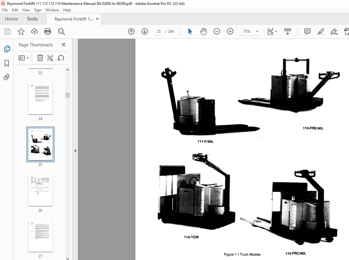
The Raymond Corporation manufactures a variety of lift trucks in both standard and
customized configurations. This Operation and Maintenance Instructions manual is
organized into major divisions which cover all areas of the truck. These include the
following:
• Safety
• Theory of Operation
• Description
• Maintenance
• Delivery Checks
• Troubleshooting
• Operating Instructions
• Addendum
Using the Manual
This manual contains several elements necessary for effective use, which are:
1. Table of Contents: guides the reader to the correct pages.
2. Lists of Illustrations: guides the reader to the correct pages.
3. Glossary: a list of definitions for technical terms and abbreviations used
throughout this manual. It is located following the List of Illustrations.
4. Safety First and Last: gives specific safety guidelines for truck operators,
owners and maintenance personnel. This information is given at the beginning of
the manual and at various areas throughout the manual where necessary.
5. Troubleshooting Charts: for quick logical tracking of troubles and suggested
remedies, located in Chapter 6.
6. Schematics: for ease of troubleshooting any part of the trucks electrical and/or
hydraulic systems, located in Chapter 7.
TABLE OF CONTENTS:
Raymond Forklift 111-F60L 112-FRE60L 113-FRC60L 114-TOW Operation & Maintenance Manual SN 3000 and up – PDF DOWNLOAD
Subject Page
SECTION I: Operation and Maintenance Instructions
Safety
Chapter 1 : Description
Chapter 2: Operating Instructions
Chapter 3: Installation
Chapter 4: Theory of Operation
Chapter 5: Maintenance
Chapter 6: Troubleshooting
Chapter 7: Appendix
Chapter 1
MODEL 110
INDEX
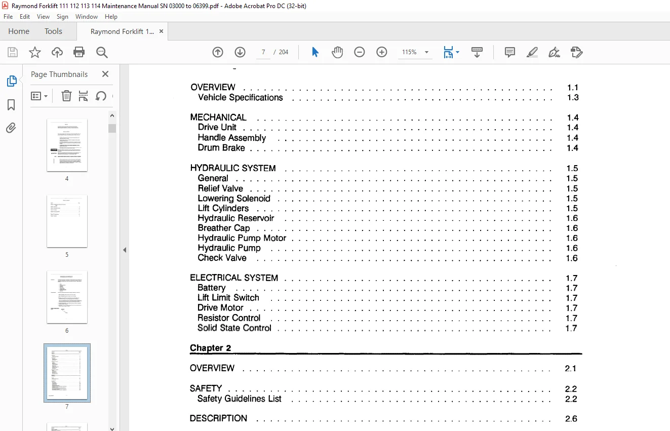
OVERVIEW 1 1
Vehicle Specifications 1 3
MECHANICAL 1 4
Drive Unit 1 4
Handle Assembly 1 4
Drum Brake 1 4
HYDRAULIC SYSTEM 1 5
General 1 5
Relief Valve 1 5
Lowering Solenoid 1 5
Lift Cylinders 1 5
Hydraulic Reservoir 1 6
Breather Cap 1 6
Hydraulic Pump Motor 1 6
Hydraulic Pump 1 6
Check Valve 1 6
ELECTRICAL SYSTEM 1 7
Battery 1 7
Lift Limit Switch 1 7
Drive Motor 1 7
Resistor Control 1 7
Solid State Control 1 7
Chapter 2
OVERVIEW 2 1
SAFETY 2 2
Safety Guidelines List 2 2
DESCRIPTION 2 6
CONTROLS 2 7
KEY SWITCH 2 9
LIFT BUTTON · 2 10
LOWER BUTTON 2 10
HORN BUTTON 2 1 O
POSITIVE DRUM BRAKE 2 11
FORWARD/REVERSE DIRECTIONAL CONTROLS 2 12
STEERING 2 12
REVERSING SWITCH 2 13
BATTERY DISCHARGE INDICATOR (OPTIONAL) 2 14
HOUR METER (OPIONAL) 2 14
HIGH SPEED CONTROL (FOURTH/ OVERDRIVE) 2 15
OPERATOR DAILY CHECKLIST
Key Switch OFF
Key Switch ON
TRUCKTRAVEL
Startup Procedure
Forward/Reverse Procedure
High Speed Operation
Steering
Lift/Lower
Stopping and Parking
Lifting a Palletized Load
Traveling
Positioning and Unloading
Chapter 3
SETUP
Checking the Battery
Connecting the Battery
Lubrication
Checking the Hydraulic System
OPERATIONAL CHECKS
Checking the Drum Brake
Checking the Fork/Lift Linkage
Checking the Reversing Switch
Receiving Inspection Guide
BREAK-IN PERIOD
Introduction
Motor
Pump
Battery
Chapter 4
OPERATION OF TRAVEL SYSTEM
Vehicle Control
Resistor Control (Three Speed)
Battery Plugged IN
Keyswitch S1 ON/ Brake switch S2 CLOSED
Directional/Speed Control Forward 1st Speed
Directional/Speed Control Forward 2nd Speed
Directional/Speed Control Forward 3rd Speed
Resistor Control (Four Speed)
Plugging Resistor Control
OPERATION OF TRAVEL SYSTEM (Cont’d )
Transistor Control (Stepless Speed)
Battery Plugged IN/ Keyswitch ON/ Brake switch Closed
Directional/Speed Control Forward
Directional/Speed Control High Speed
Emergency Button – Transistor Control
Plugging Transistor Control
Lift/Lower System
Electrical Keyswitch S 1 ON
Electrical Lift Switch S4A Closed
Hydraulic Action
Electrical Lift switch S4A Opened
Electrical Lower Switch S4B
Chapter 5
SCHEDULED MAINTENANCE
Lubrication and Maintenance Guide
Daily or Every 8 Operating Hours
Weekly or Every 50 Operating Hours
Every 100 Hours
Monthly or Every 200 Operating Hours
Every 500 Hours
Semi-Annually or Every 1 ,000 Hours
LIBRICATION
Hydraulic System Oil
DRIVE UNIT
Drive Unit Service
Drive Housing Lubrication
Drive Housing Vent Plug
Drive Housing Support Bearing
Disassembly
Reassembly of Transmission
Pinion Shaft Disassembly
Drive Gear Case Data
Drive Unit Installation
DRUM BRAKE
Daily Inspection
After Every 500 Hours of Operation
Brake Adjustment
HANDLE ASSEMBLY
Adjustment (Model 111 and 112)
Tension Spring Removal and Replacement (Model 111 and 112)
Daily Inspection
After Every 50 Hours of Operation
After Every 200 Hours of Operation
Cushion Drive Tire Replacement
LOAD WHEELS
Daily Inspection
After Every 50 Hours of Operation
After Every 500 Hours of Operation
Wheel Replacement
CASTERS
Daily Inspection
After Every 50 Hours of Operation
FORK AND LINKAGE
After Every 50 Hours of Operation
Fork Height Adjustment
Lowered Fork Height
Lift Limit Switch Adjustment
HYDRAULIC MAINTENANCE
Inspection Daily
500 Hours
Hydraulic Reservoir
Checking and Adjusting Hydraulic Pump Relief Valve Pressure
Relief Valve Settings
Hydraulic Reservoir
Inspection Every 8 Hours
Inspection Every 200 Hours
Inspection Every 1,000 Hours
Lift Cylinders Service
Oil Leakage Front Cover
ELECTRICAL MAINTENANCE
Daily Checks Battery
Electrolyte Level
Specific Gravity
The Exterior of the Battery Daily Checks
Battery Charging
Battery Storage
Motor Adjustments and Inspection
Brushes
Commutator
Inspection
Servicing
High Mica
Resurfacing
Drive Motor General Data
Drive Motor Inspection
INDEX
Drive Motor Removal
Hydraulic Pump Motor General Data
Hydraulic Pump Motor Inspection
Hydraulic Pump Motor Removal
Electrical System Adjustments
Potentiometer Adjustments
Resistor Control
Solid State Control
Limit Switch Adjustment
Drive Motor Cutout Switch Adjustment
Contactors: General Information
Cleaning
Inspection
Contactor Tip Inspection
Contactor Table
Contactor Maintenance
Contactor Coil Replacement
Replacement of Contactor Tips, Insulation and/or Carew Rod Assembly
Disassembly/Reassembly
Checking Components
Transistors
Diodes
Testing Other Components
Welding Precautions
Chapter 6
OVERVIEW
Suggestions
RESISTOR CONTROLS
Listing of Problems
TRANSISTOR CONTROLS
Listing of Problems
COMMON FOR ALL TRUCKS
Electrical Symbols
Electrical Schematic for Models 111-F/60L (Resistor)
Electrical Schematic for Models 112-FRE/60L (Resistor)
Electrical Schematic for Models 113-FRC/60L (Resistor)
Electrical Schematic for Models 114-TOW (Resistor)
Legend Electrical Schematics
Electrical Schematic for Models 112-FRE/60L (Solid State)
Electrical Schematic for Models 113-FRC/60L (Solid State)
Electrical Schematic for Models 114-TOW (Solid State)
Wiring Diagrams for Models 111-F/60L (Resistor)
Wiring Diagrams for Models 112-FRE/60L (Resistor)
Wiring Diagrams for Models 113-FRC/60L (Resistor)
Wiring Diagrams for Models 114-TOW (Resistor)
Wiring Diagrams for Models 112-FRE/60L (Solid State)
Wiring Diagrams for Models 113-FRC/60L (Solid State)
Wiring Diagrams for Models 114-TOW (Solid State)
Test Point Locations
Hydraulic Schematic
IMAGES PREVIEW OF THE MANUAL:
Customer Support: [email protected]
PLEASE NOTE:
- This is the SAME exact manual used by your dealers to fix your vehicle.
- The same can be yours in the next 2-3 mins as you will be directed to the download page immediately after paying for the manual.
- Any queries / doubts regarding your purchase, please feel free to contact [email protected]
S.V