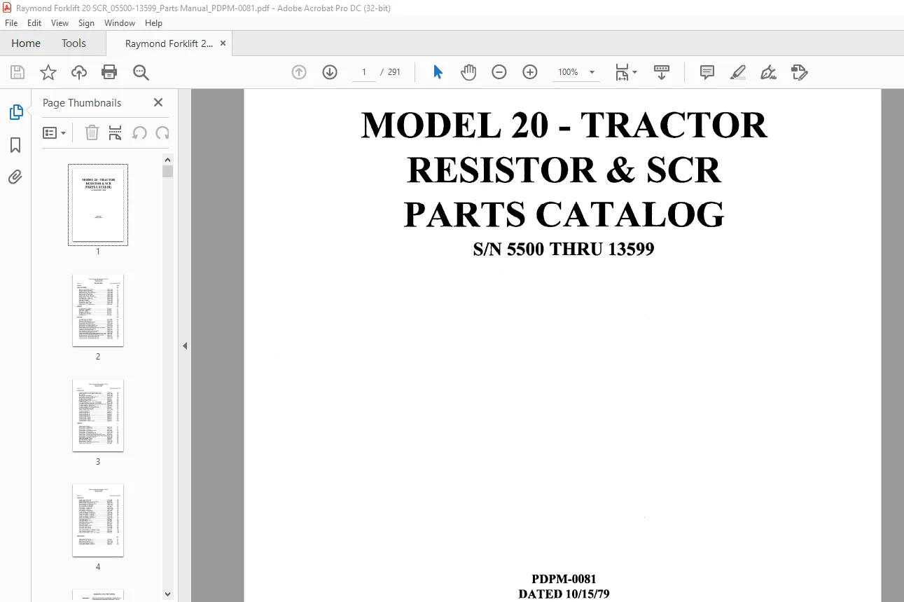
Raymond Forklift 20 Tractor Resistor & SCR Parts Catalog Manual SN 5500 Thru 13599 – PDF DOWNLOAD
Original price was: $86.95.$28.95Current price is: $28.95.
Raymond Forklift 20 Tractor Resistor & SCR Parts Catalog Manual SN 5500 Thru 13599 – PDF DOWNLOAD
Description
Raymond Forklift 20 Tractor Resistor & SCR Parts Catalog Manual SN 5500 Thru 13599 – PDF DOWNLOAD
FILE DETAILS:
Raymond Forklift 20 Tractor Resistor & SCR Parts Catalog Manual SN 5500 Thru 13599 – PDF DOWNLOAD
Language : English
Pages : 291
Downloadable : Yes
File Type : PDF
DESCRIPTION:
Raymond Forklift 20 Tractor Resistor & SCR Parts Catalog Manual SN 5500 Thru 13599 – PDF DOWNLOAD
Introduction to Your Parts Catalog:
Introduction:
The Raymond Corporation manufactures a variety of lift trucks in both standard and customized configurations. The Parts
Catalog is organized into major divisions which cover all areas of the truck. These may include:
• Power Unit (if applicable) • Hydraulic (if applicable)
• Brake and Steering • Elevating/ Attachments
• Drive Unit • Contadors
• Electrical • Special Options fif applicable)
Using the Catalog:
The catalog contains three elements necessary for effedive use, which are:
1. Quality Assurance Sheet gives specific components in a truck and is located at the beginning of the parts catalog.
2. Table of Contents guides the reader to the corred pages.
3. Customized Prints provide special documentation for customized trucks and are located at the end of the parts catalog.
Parts Catalog Overview:
• In some cases, large assemblies or installations are broken down over several pages.
Example: The DRIVE UNIT assembly is shown on one page — the DRIVE MOTOR for this drive unit on another page — the DRIVE WHEEL for this unit on another page.
• Drawings of hydraulic hoses and piping do not necessarily conform to exad installation as they appear on the truck.
These illustrations are for part number references only.
• An indented part number indicates the part is a component of the preceding non-indented part and can be ordered separately; however, the component will be included when the non-indented part is ordered.
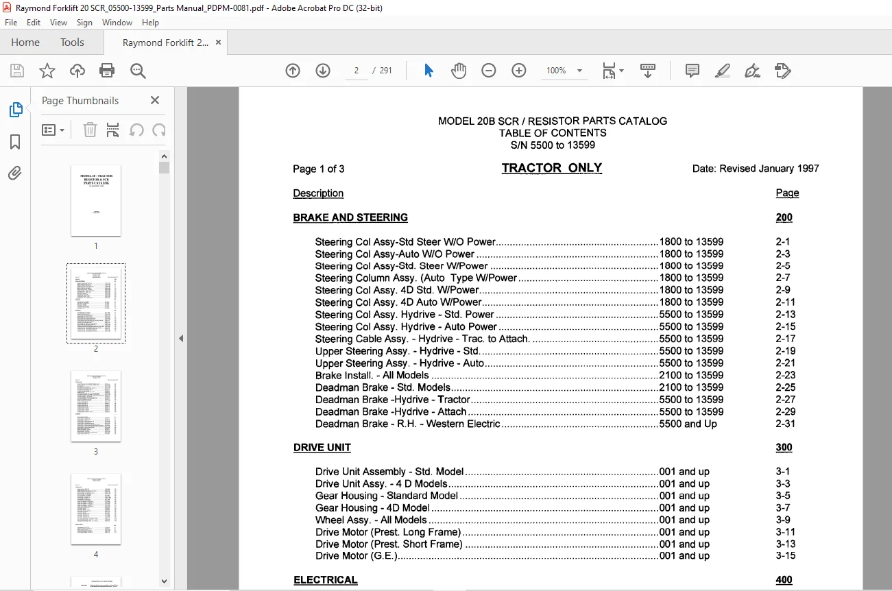
TABLE OF CONTENTS:
Raymond Forklift 20 Tractor Resistor & SCR Parts Catalog Manual SN 5500 Thru 13599 – PDF DOWNLOAD
BRAKE AND STEERING 200
Steering Col Assy-Std Steer W/O Power 1800 to 13599 2-1
Steering Col Assy-Auto W/O Power 1800 to 13599 2-3
Steering Col Assy-Std Steer W/Power 1800 to 13599 2-5
Steering Column Assy (Auto Type W/Power 1800 to 13599 2-7
Steering Col Assy 4D Std W/Power 1800 to 13599 2-9
Steering Col Assy 4D Auto W/Power 1800 to 13599 2-11
Steering Col Assy Hydrive – Std Power 5500 to 13599 2-13
Steering Col Assy Hydrive -Auto Power 5500 to 13599 2-15
Steering Cable Assy – Hydrive – Trac to Attach 5500 to 13599 2-17
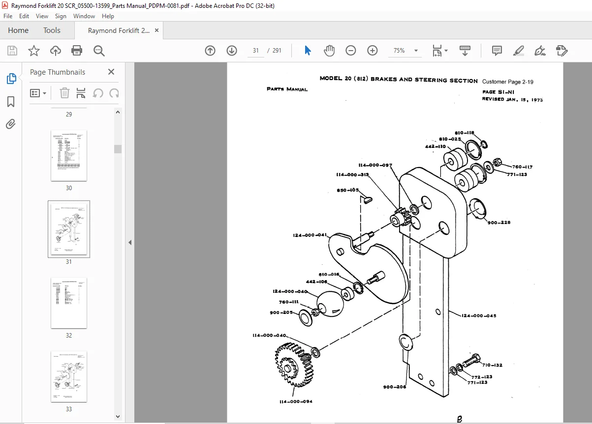
Upper Steering Assy – Hydrive – Std 5500 to 13599 2-19
Upper Steering Assy – Hydrive -Auto 5500 to 13599 2-21
Brake Install -All Models 2100 to 13599 2-23
Deadman Brake – Std Models 2100 to 13599 2-25
Dead man Brake -Hydrive – Tractor 5500 to 13599 2-27
Dead man Brake -Hydrive – Attach 5500 to 13599 2-29
Deadman Brake – R H – Western Electric 5500 and Up 2-31
DRIVE UNIT 300
Drive Unit Assembly – Std Model 001 and up 3-1
Drive Unit Assy – 4 D Models 001 and up 3-3
Gear Housing – Standard Model 001 and up 3-5
Gear Housing – 4D Model 001 and up 3-7
Wheel Assy -All Models 001 and up 3-9
Drive Motor (Prest Long Frame) 001 and up 3-11
Drive Motor (Prest Short Frame) 001 and up 3-13
Drive Motor (G E ) 001 and up 3-15
ELECTRICAL 400
Standard Electrical Symbols 4-1
Quickie Ref Of Elec Comp Resistor 001 to 10450 4-3
Quickie Ref Of Elec Comp SCR 5500 to 10458 4-5
Electrical System 812-002-700/(W) Resistor 5500 and up 4-7
Electrical System 154-005-000/(T) SCR 5500 to 13599 4-9
Electrical System 124-000-240 Resistor Hydrive 5500 to 9502 4-11
Electrical System 154-005-070 SCR Hy drive 5500 to 9502 4-13
Electrical System 124-000-240(J) Resistor Hydrive 9503 to 13599 4-15
Electrical System 154-005-070/(N)SCR Hydrive 9503 to 13599 4-17
Electrical Remote Install 812-002-790/(F) SCR & RES Std W/Remote 9503 and up 4-19
Controller Assembly 154-002-520/(F) Resistor 5500 and up 4-21
Controller Assy 154-002-500/ (W) SCR 5500 to 11461 4-23
Upper Controller Assy Resistor Hydrive 124-000-250/ 5500 and up 4-25
Upper Controller Assy SCR Hydrive 154-005-073 5500 to 13599 4-27
Controller Assy 154-002-500(AB) SCR 11462 to 13599 4-29
Contactor Panel Assembly 812-002-705/002 Resistor W/o Aux & P Steer 5500 to 7850 4-31
Contactor Panel Assy 154-005-004/002 – SCR w/o Aux & P Steer 5500 to 7850 4-33
Contactor Panel Assy 812-002-705/001(R) Resitor Std 5500 and up 4-35
Contactor Panel Assy 154-005-004/001(U) Std SCR 5500 to 13599 4-37
Contactor Panel Assy 154-005-004/003(U) SCR Low lifts West Elec & Std 5500 to 13599 4-39
Contactor Panel Assy 154-005-004/004 SCR Hydrive 5500 to 13599 4-41
Contactor Panel Assy 812-001-705/003 (P) Resistor Low lift 5500 and up 4-43
Contactor Panell Assy 812-002-705/004(K) Resistor Hydrive 5500 to 13599 4-45
Meter Installation 5500 to 13599 4-4 7
Main SCR Install 154-005-008 (L) 5500 to 13599 4-49
Commutating SCR and Rectifier Install 154-005-012 5500 to 13599 4-51
Battery Connector Installation 154-005-039 5500 and up 4-53
EC Battery Connector Assembly (B) 5500 and up 4-55
YC Battery Connector Assembly 5500 and up 4-57
Electrical Supply – Remote Control 812-002-740 5500 to 9502 4-59
Resistor and Cover 5500 and up 4-61
Low Voltage Circuit Breaker Std + Low Lift 154-005-060/002 5500 to 13599 4-63
Low Voltage Circuit Breaker Cold Storage 1514-005-060/001 5500 to 13599 4-65
Limit Switch Installation -High Spd Clear -Height cut out 812-001-270/ (G) 5500 to 9502 4-67
Limit Switch Installation – High Spd Clear 9503 and up 4-69
Limit Switch Installation 821-001-238/ high spd cut out 12813 and up 4-71
Limit Switch Installation 821-001-248/ high spd cut out 5500 and up 4-73
Warning Light Installation 821-001-262/ 5500 and up 4-75
Spotlight Installation 812-001-566/ (D) 5500 to 13599 4-77
Control Unit Assembly 154-005-020 (G) SCR 5500 to 13599 4-79
Contactor Assembly 590-170 5500 and up 4-81
Contactor Assembly 590-171 5500 and up 4-83
Contactor Assembly 590-172 5500 and up 4-85
Contactor Assembly 590-176 5500 and up 4-87
Contactor Assembly 1-105-007/ 1-105-012 5500 and up 4-89
Contactor Assembly 590-150 5500 and up 4 91
Contactor Assembly 1-150-054 5500 and up 4-93
Contactor Assembly 1-105-009 5500 and up 4-95
Contactor Assembly 1-105-029 5500 and up 4-97
Contactor Assembly 1-105-040 5500 and up 4-99
Contactor Assembly 1-105-072/ 1-105-079 5500 and up 4-101
Standard Hydraulic Symbols 5-1
Hydraulic System – 812-002-691 (A) 5500 to 9958 5-3
Hydraulic System – 812002-691 (B) 5500 and up 5-5
Hydraulic System (Hydrive) -124-000-271 (B) 5500 to 13599 5-7
Hydraulic System – 812-002-745/ 5500 and up 5-9
Hydraulic System – 812-002-661/003 and /004 5640 to 5849 5-11
Hydraulic System – 812-002-745/ (M) 5500 to 13599 5-13
Hydraulic System – 812-002661/007 and /008 5640 to 5849 5-15
Hydraulic System – 812-002-745/ Std, Remote,w/Aux control 5500 and up 5-17
Hydraulic System – 812-002-661/005 and /006 Std Steer w/ Aux control 5640 to 5849 5-19
Hydraulic System – 812-002-745/ (M) Std, Remote Control, Power Str,W/Aux 5500 to 13599 5-21
Hydraulic System – 812-002-661/001,/002,/009 5640 to 5849 5-23
Valve Assembly – 812-002-696 5500 to 15817 5-25
Solenoid Valve Assembly – 520-449 5500 and up 5-27
Check Valve Assembly – 520-307 5500 and up 5-29
Manifold Assembly – 124-000-281 5500 to 13599 5-31
Manifold Assembly -Resistor Reach – 812-002-746/ (B) 5500 to 1500 5-33
Manifold Assembly – Std – 812-002-629 5640 to 5849 5-35
Auxiliary Controls – 812-001-352 001 to 9958 5-37
Auxiliary Controls – 812-001-350 2175 to 9958 5-39
Auxiliary Controls – 812-000-271 2175 to 9958 5-41
Auxiliary Controls Piping -812-002-100/ (C) I 0991 (C) 9959 and up 5-43
Reservoir Assembly – 812-002-597 (G) Std 5500 to 13599 5-45
Reservoir Assembly – 812-002-683 (F) Low Lift 5500 to 13599 5-47
Lift Pump and Motor – 812-002-604 (B) 5500 to 14000 5-49
Lift Pump and Motor – 812-002-780 (E) 5-51
Aux Pump and Motor – 812-002-608 001 to 9958 5-53
Pump and Motor- 812-002-607 (E) 5500 to 10483 5-55
Pump and Motor – 812-002-811 (B) 10484 to 13599 5-57
Pump and Motor – 812-002-820 10484 to 13599 5-59
Torque Generator-812-000-229 (F) 001 to 13599 5-61
Lift Valve Assembly – 812-002-598 (D) 5500 and up 5-63
Auxiliary Valve Installation – 812-001-352 (J) 2710 to 9958 5-65
Auxiliary Valve Installation – 812-002-802/ (C) 9959 to 15540 5-67
Auxiliary Valve Installation – 812-001-350 2710 to 9958 5-69
Auxiliary Valve Installation – 812-002-803/ (E) 9959 to 15211 5-71
Auxiliary Valve Installation – 812-000-571 2710 to 9958 5-73
Auxiliary Valve Installation – 812-002-804 (C) 9959 to 15540 5-75
Control Valve (Lift) – 520-041 (B) 5500 and up 5-77
Control Valve – 520-037 001 to 9958 5-79
Control Valve Assembly – 520-043 9959 and up 5-81
Control Valve – 520-038 001 to 9958 5-83
Control Valve Assembly – 520-044 (E) 9958 to 15211 5-85
Control Valve Aux – 520-044 9959 to 15211 5-87
Control Valve – 520-039 001 to 9958 5-89
Control Valve Assembly – 520-053 9959 and up 5-91
Control Valve – 812-001-351 (L) 3412 to 9958 5-93
Control Valve – 812-001-353 (N) 3413 to 9958 5-95
Control Valve – 812-001-172 (N) 3413 to 9958 5-97
Tractor to Attachment Piping 5500 and up 5-99
Tractor to Attachment Piping – 112-000-669/ (C, /769/ (C) 5500 and up 5-101
Tractor to Attachment Piping – Low Lift 5500 to 9958 5-103
Tractor to Attachment Piping – Low Lift – 761-151-089 (C) 9959 and up 5-105
MISCELLANEOUS
Caster Assembly- 812-001-259 1370 and up 6-1
Caster Leg Assembly -112-000-574/ (J) 001 and up 6-3
Doors & Covers – 812-003-021 5500 to 13599 6-7
Indicator Cover Assembly – 812-002-613 5500 to 13599 6-9
Battery Compartment – 812-002-000 001 to 13599 6-11
Counter weights Installation – 812-000-113 5500 and up 6-13
IMAGES PREVIEW OF THE MANUAL:
Customer Support: [email protected]
PLEASE NOTE:
- This is the SAME manual used by the dealers to troubleshoot any faults in your vehicle. This can be yours in 2 minutes after the payment is made.
- Contact us at [email protected] should you have any queries before your purchase or that you need any other service / repair / parts operators manual.
S.V