Raymond Forklift 20i 21i 21i PLUS Operation Maintenance Manual SN 29000 and Up – PDF DOWNLOAD
$28.95
Raymond Forklift 20i 21i 21i PLUS Operation Maintenance Manual SN 29000 and Up – PDF DOWNLOAD
Description
Raymond Forklift 20i 21i 21i PLUS Operation Maintenance Manual SN 29000 and Up – PDF DOWNLOAD
FILE DETAILS:
Raymond Forklift 20i 21i 21i PLUS Operation Maintenance Manual SN 29000 and Up – PDF DOWNLOAD
Language : English
Pages :318
Downloadable : Yes
File Type : PDF
Size:32.9 MB
DESCRIPTION:
Raymond Forklift 20i 21i 21i PLUS Operation Maintenance Manual SN 29000 and Up – PDF DOWNLOAD
PREFACE
This manual presents factual material on the Raymond Corporation equipment you have purchased. The object is to insure safe operation and/or maintenance practices and procedures for this Raymond product
MANUAL OVERVIEW
This manual consists of both the Operating and Maintenance (O&M) section and the Parts Catalog (P/C) section for the specific equipment listed on the cover
• Description
• Installation
• Operating Instructions
• Theory of Operation
• Maintenance
• Troubleshooting
• Appendix
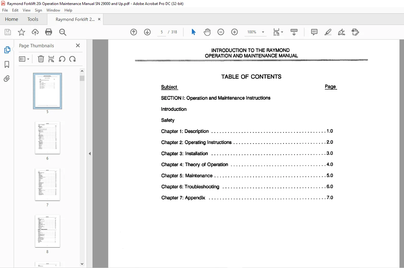
TABLE OF CONTENTS:
Raymond Forklift 20i 21i 21i PLUS Operation Maintenance Manual SN 29000 and Up – PDF DOWNLOAD
SECTION I: Operation and Maintenance Instructions
Introduction
Safety
Chapter 1 : Description 1 0
Chapter 2: Operating Instructions 2 0
Chapter 3: Installation 3 0
Chapter 4: Theory of Operation 4 0
Chapter 5: Maintenance 5 0
Chapter 6: Troubleshooting 6 0
Chapter 7: Appendix 7 0
Ill
Model 20i/21 i
General Index
Chapter 1 – Description
SUBJECT
TRUCK OVERVIEW
“i• Series Description
Model 20i
Model 21i
lYPICAL VEHICLE SPECIFICATIONS (Model 20i)
lYPICAL VEHICLE SPECIFICATIONS (Model 2li)
Description
MECHANICAL SECTION
Chassis
Chassis Parts Description
Truck Frame
Bumper
Front
Door
Covers
Operator’s Compartment
Battery Compartment
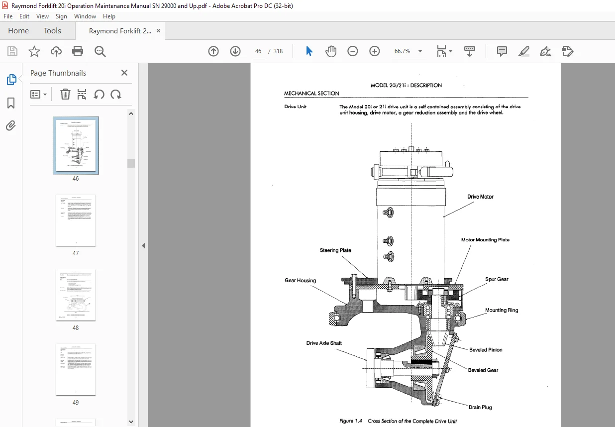
Drive Unit
Drive Unit Parts Description
Gear Housing
Drive Motor
Gear Reduction Assembly
Drive Wheel
Swivel Caster
Swivel Caster Parts Description
Tires
Springs
Trac-Qualizer
Power Caster (4D)
HYDRAULIC SECTION
Brake
Brake Parts Description
Deadman Pedal
Brake Master Cylinder
Slave Cylinder
Brake Adjusting Screw
Steering
Parts Description
Steering Wheel
Gearbox
Steering Column
Spur Gears
Torque Generator
4D Steering
Travel Mode Selector
Caster Load Wheel
HYDRAULIC SECTION (Cont’d )
Lift/Lower
Parts Description
Lift Pump
Lift Motor
Lift/Lower Control Valve
Manifold Assembly
Travel Lift Solenoid
Travel Lower Solenoid
Pressure Relief Valve
Low Pressure Adjustable Relief Valve
Check Valve
Flow Control Valves
Travel Lift/Lower Switch
Main Flow Control
Lift Cylinder
Oil Filter
Reservoir
P Contactor
Pump
Motor
Control Valve
Load Holding Check Valve
Lift Cylinder Flow Control
Auxiliary Contactor
Auxiliary Functions
Parts Description
Auxiliary Motor
Auxiliary Pump
Torque Generator
Spool Valves
Equalization Solenoid
Carriage Manifold
ELECTRICAL SECTION
Travel System
Parts Description
Keyswitch
Directional/Speed Control Assembly
Travel Contactors
Potentiometer VRl
Drive Motor
Keyswitch Relay Kl
Deadman Switch S2
SCR’s
Charging Rectifier (RECl)
Plugging Rectifier (REC3)
Recirculating Rectifier (REC2)
Transformer (Tl )
Model 20i/21i
General Index
ELECTRICAL SECTION (Cont’d)
1 S Contactor
P O Module
Resistor R2
Capacitors (Cl, C2, C3 and C4)
Fuses
Control Unit •
“intellidrive” Control Unit
Safety circuits: •
Diagnostics
Throttle Card Assembly
Transient Suppressors
Miscellaneous Circuit Parts Description
Hom
Hour Meter
Curtis Battery Controller
Optional Circuits Parts Description
Lights
Remote lift/Lower
Power Disconnect
Limit Switches
Model 20i/21 i
General Index
Chapter 2 – Operating Instructions
INTRODUCTION
CONTROLS
Keyswitch
Battery Disconnect
Reach Lever
Lift/lower – Travel Lift/lower
Tilt Lever
Steering Wheel
Drive Wheel Direction Indicator (4-D)
Travel Mode Selector Handle (4-D)
Travel Mode Indicators ( 4-D)
Directional/ Speed Control Handle
Hom Button
Hour Meter
Working Lights (optional)
Flashing/rotating Lights (optional)
Remote Lift/lower (optional)
OPERATOR DAILY CHECKLIST
Checks with the keyswitch OFF
Checks with keyswitch ON
TRUCK TRAVEL
Startup Procedure
Forward and Reverse
4D Steering
General Index
Subiect
TRUCK TRAVEL (Cont’d)
Plugging
lift/Lower
Main lift/Lower
Travel lift/Lower
Auxiliary Functions Process (Reach and Tilt)
Ramp Operation
Turning Into an Aisle
Entering and Leaving Pallets
A With a Straddle Truck
B With a Reach Truck
Parking
Speed Limitation
SAFETY
Safety Guidelines List
Chapter 3 – Installation
RECEIVING TRUCK
Reasons For Visual Inspections
What To Look For
Visual Inspection/Conditions
Visual Inspection Checklist
Cradled Trucks
Visual Inspection
UNCRADLING
Uprighting a Cradled Vehicle
Procedure # 1
Gasket Removal
Types of Oils
Procedure #2
Gasket Removal
Types of Oils
FUNTIONAL INSPECTION
Vehicle Operation
Warranty
What To Look For
Functional Installation Check List
COLD STORAGE CONDITIONING
Classes Of Cold Storage
Hydraulic System Oil Change Procedure
Drive Unit Procedures
BATTERY
Battery Charger
~, Battery Installation
Suggested Connector Voltage Color Coding
SUBJECT
STORAGE
Storage Warranty
Motors
Hydraulic System •
Hydraulic Cylinders
Lift/Steering Chains
Electronics
Battery
Vehicle – General
Model 20i/21 i
General Index
Chapter 4 Theory Of Operation
OVERVIEW
Presentation
Outline
LIFT
Lift Process
LOWER
Lower Process
TRAVEL LIFT/LOWER
Travel Lift Process
Travel Lower Process
AUXILIARY SYSTEM
Auxiliary System Process
Power Steering
SCR THEORY
SCR Description
SCR Switching
TRAVEL CIRCUIT COMPONENTS
Throttle Card
Microprocessor Control Card (I C C )
Travel Circuit Components/Function
I C C Circuits
OPERATION OF TRAVEL SYSTEM
Battery Plugged In
Keyswitch (Sl) Turned ‘ON’
Closing Deadman Switch (S2)
Moving Directional/Speed Control
‘M’ Speed (By-pass) Operation
Plugging
1 S Contactor
Resistor R2
P D Module
D C MOTOR BRUSHES
Carbon Brushes
Film Foundation
Commutator Film Action
Brush Spring Pressure
SCHEDULED MAINTENANCE
Daily or every 8 Operating hours, whichever occurs first
Weekly or every 40 operating hours, whichever occurs first
Monthly or every 175 operating hours, whichever occurs first
Annually or every 1,000 operating hours, whichever occurs first
Straddle/Reach Attachment
Straddle/Reach Lubrication Points
TORQUE DATA
TRUCK JACKING
MECHANICAL
Drive Unit
Drive Motor Cleaning and Inspection
Drive Motor Replacement
Drive Wheel Replacement
Drive Unit Removal
Drive Unit Disassembly
Drive Unit Reassembly and Installation
Brake Adjustment
Plug Adjustment
Brake Shoe Adjustment
Brake Bleeding
Deadman Pedal Adjustment
Steering
Steering Checklist
Steering Assembly Removal
Steering Disassembly/ Assembly
Swivel Caster and/ or T rac-Qualizer
Swivel Caster and/or Trac-Qualizer Checklist
Swivel Caster and/or Trac-Qualizer Disassembly/Assembly
Checklist
Swivel Caster and/or Trac-Qualizer Spring Adjustment
Swivel Caster Height Adjustment
Trac-Qualizer Height Adjustment
Lift Chain
Removal
Defect-Cause Maintenance Chart
Lift Chain Lubrication
Equalization Chain Lubrication
Equalization Chain Adjustment (TT)
Equalization ChainRemoval/lnstallation (TT)
Reach Carriage Chain Anchors
Replacing Mast Bumpers
Mechanical Stop Adjustment
Equalization Chain Sheave Replacement
Over The Mast Hose/Cable Adjustment
Over The Mast Hose Replacement
Control Replacement (TT Mast)
Subject
HYDRAULIC MAINTENANCE
Leakage
Hydraulic Leakage Fault-Prevention Chart
System Contamination
System Contamination Fault Prevention Chart
Incorrect Valve Pressure Settings
General Hydraulic Maintenance “Tips”
Hydraulic Oil and Filter
Hydraulic Oil and Filter Checklist
Lift and Auxiliary Pump
Lift Pump Replacement
Auxiliary Pump Replacement
Auxiliary Pump Repair
Lift Pump Service
Lift Pump Disassembly
Lift Pump Inspection
Lift Pump Assembly
Hydraulic Manifolds
Lift/LowerControl Valve
Hydraulic System Pressure Tester
Lift Pressure Relief Valve Adjustment
Carriage Drift
Low Pressure Relief Valve Adjustment
Solenoid Valves
Solenoid Valve Test
Power Steering Relief Valve Test
Auxiliary Control Valve
Spool Valve Disassembly
Spool Valve Parts Inspection
Relief Valve Service
Spool Valve Reassembly
Air In The Hydraulic System
Bleeding Air From Lift Cylinder
Auxiliary Control Switches (S6, S7, SB)
Power Caster – 4D Steering
Miscellaneous Hydraulic Maintenance
Repacking Lift Cylinders
Repacking Procedure (except side cylinders)
ELECTRICAL
Wiring Harness
Shorts To Frame
Shorts to Frame Test
Motor Carbon Buildup
Heat Sink insulation
Other resistances
Battery
Record Keeping
Cleaning
Electrolyte Process
Battery Cleaning
Battery Electrical Leakage to Frame Test
Hydrometer Check
Voltage Check
Watering
Guidelines
Battery controller (Curtis)
General
Battery controllerTest Units
Slow Test Using 1142
Fast Test Using 1141
Battery Controller Adjustments
Reset Potentiometer
Reset Potentiometer Adjustments
Discharge Potentiometer
Discharge Potentiometer Adjustment
Reset and Discharge Setting Values
Motors
Motor Cleaning
Brush Care
Maintenance Schedule
Inspection
Brush Replacement
Commutator Care
Inspection
Commutator Servicing
High Mica
Commutator Resurfacing
Stoning of MotorCommutators
Commutator Segment Trueness
Chamfering Commutator Bar Edges
Motor Overheating
Cause-Prevention Table
Motor Test For Open Circuit
Drive Motor Open Circuit Test
Short Circuit Test – Motor
Short Circuit test
Armature Shorts
Motor Grounds Test
Model 20i/21 i
General Index
General Index
Subject
ELECTRICAL (cont’d)
Contactors
General information
Cleaning
Inspection
Contactor Tip Inspection
Contactor Table
Contactors Maintenance
Contactor Coil replacement
Replacement Of Contactor Tips, Insulation And/or Core And Rod Assembly
Disassembly/Reassembly
Diagnostic Test Unit
System Status Codes
Battery Voltage into the “intellidrive” Control Unit Check (using the test cable)
Regulated Voltage
Throttle Card Null Adjustment
Throttle Card Speed Limit Adjustment
“lntellidrive” Control Installation
Voltage Regulator
Cold Storage Application
“lntellidrive” System Adjustment w/Throttle Card 114-007-329/003
Current Limit Adjustment – Potentiometer “M”
Plugging Adjustment – Potentiometer “B”
Procedure
Ramp Acceleration Adjustment Potentiometer
Directional/ Speed controller
Removal From Vehicle
Potentiometer Removal/ Disassembly
Electrical Assembly
Directional/ Speed Control Assembly
Diode Assemblies
DA2 checks
DA3 and DA5 checks
DA7 checks
DAS checks
DAl 1 checks
DA 1 0 and DA 12 checks
DA13 Checks
DA14 Checks
Transient Suppressors
Suppressor List
Test Specifications
Relays
Test Procedure For Kl Relay
Testing Other Electrical components
XII
Chapter 6 – Troubleshooting
Subiect
OVERVIEW
WIRING – GENERAL • • •
Discharge Capacitor • •
TRUCK COMPLETELY INOPERATIVE
TRAVEL CIRCUIT/1 C C PROBLEMS
I C C Control Display Codes
System Status Codes • • • • • • • •
Model 20i/21 i
General Index
Fault Codes • • • • • • • • • • • • • • • •
Motor Overheats/Poor Brush Life (Model 21 i PLUS Only)
R2 Overheats (Model 21 i PLUS Only)
LIFT/LOWER PROBLEMS
HYDRAULIC PROBLEMS
AUXILIARY PUMP PROBLEMS
AUXILIARY SYSTEM PROBLEMS
CURTIS BATTERY CONTROLLER PROBLEMS
Battery Controller Will Not Reset
Fuel Gauge Remains at Full
No Lockout ••
No Lift • •• ••
HORN INOPERATIVE
Chapter 7 – Appendix
Subject
Lubrication Equivalency Chart
Electrical Schematic (Sheet 1 of 2)
Electrical Schematic (Sheet 2 of 2)
Wiring Diagram (Sheet 1 of 4) •
Wiring Diagram (Sheet 2 of 4)
Wiring Diagram (Sheet 3 of 4)
Wiring Diagram (Sheet 4 of 4)
Legend – Electrical Schematics and Wiring Diagrams
Notes for Electrical Schematics
Notes for Wiring Diagrams
Hydraulic Schematic (standard)
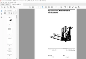
Model 20i/21 i Fork Lift Truck
Model 20i/21 i With Door Open and Covers Removed
Model 20i/21 i Chassis
Cross Section of the Complete Drive Unit
Cross Section of Swivel Caster with T rac-Qualizer
Brake Installation
Gears for Automotive and Standard Steering
Definition of 4D Travel Direction
Hydraulic System Components
1 S Contactor/P D Module Location Reference
Electrical Panel
Operator Controls
Drive Wheel Indicator and Caster Indicator Lights
Remote Lift/Lower Controls
Side Travel Directional Reference
Straddle Truck Entering Pallet
Reach Truck Entering Pallet
Safety Decal
Lift – Lift Motor/Pump ON – Control Valve Open
Lift – Lift/Lower Control Valve Closing
Lower
Travel Lift
Travel Lower
Auxiliary System
SCR Physical Appearance
SCR Electrical Symbol
Diagram of How an SCR Operates
Throttle Card Schematic
Travel Circuit
Battery Plugged In – Sheet l of 2
Battery Plugged In – Sheet 2 of 2
Keyswitch Turned – ON – Sheet 1 of 2
Keyswitch Turned – ON – Sheet 2 of 2
Deadman Switch Depressed – Sheet l of 2
Deadman Switch Depressed – Sheet 2 of 2
Turning ON the Main SCRl and Charging Capacitors Cl, C2, C3, C4
Turning OFF the Main SCRl
Control Handle Movement
High Speed M Range
Operation of 1 S, R2, and P O Module
Plugging
Chapter 5 – Maintenance
Scheduled Maintenance Chart
Lubrication Equivalency Chart
Straddle/Reach Attachment Lubrication
Standard Torque Data for Bolts
Correct Jacking Locations for the Model 20i/21 i
Drive Unit
Cross Section of the Drive Unit
Drive Motor Installation (Typical)
Drive Wheel
Fabricated Ring for Removing the Drive Unit
Proper Position of Thrust and Radial Rings
Exploded View of Brake Assembly
Brake Bleed Procedure
Deadman Pedal Adjustment
Steering Column Assembly Power Steering, Standard Type
Exploded View of the Swivel Caster •
Pre-loading Caster and/or Trac-Qualizer Springs
Lift Chain Lubrication
Adjusting Equalization Chain Anchor
Blocking the Mast
Reinstalling Equalization Chain
Reach Carriage Chain Anchors
Mast Bumper Installation
Mechanical Stop Adjustment – Typical
Removing Equalization Chain Sheave
Blocking Mast
Hose Clamping On Inner Telescopic
Hose/Cable Tension Spring Adjustment
Blocking Reach Mast
Hose Routing Detail
Rear TT Cylinder Piston/End Cap
TT Mast Flow Control – Exploded View
View of Hydraulic Components
Hydraulic Control Valves
Auxiliary Pump -P/N 500-417-200 or 201: Exploded View
Lift Pump -P/N 500-417-100: Exploded View
Lift Pump P /N 500-41 7 -1 00: Sectional View
Shaft Seal
Right Hand Rotation view From Cover End
Hydraulic Components
Maximum Rate of Allowable Load Drop
Spool Valve – Exploded View
Auxiliary Control Switches S6, S7, and S8
40 – Power Caster – Load Wheel
Lih Cylinder Packing
Battery Controller Tester (Curtis)
Pot Settings and Volts per Cell
Cleaning A Motor (Typical)
Maintenance Inspection Chart
Measuring Spring Tension
Table of Brush Lengths and Spring Pressures
Mica Undercutting •
Commutator Cutting Tool
Proper Technique of Chamfering Commutator Segments
Chamfering Segment Bar Edges on the Commutator
Drive Motor Terminals and Circuits
Contactor Specfications
Typical Contactor Exploded View
“intellidrive” and Test Unit (P/N 154-008-767)
Throttle Card Nulling (VRl)
Throttle Card Adjustment Points
“lntellidrive” Adjustment Potentiometers
Throttle Control Card – II (T C C -11) Adjustment Points
Directional/Speed Control Assembly
Directional/Speed Control – Exploded View
Contactor Suppressors
Electrical Components Test
SCR Torque Ratings and Installation
Chapter 6 – Troubleshooting
Lubrication Equivalency Chart
Electrical Schematic (Sheet l of 2)
Electrical Schematic (Sheet 2 of 2)
Wiring Diagram (Sheet l of 4
Wiring Diagram (Sheet 2 of 4)
Wiring Diagram (Sheet 3 of 4)
Wiring Diagram (Sheet 4 of 4)
IMAGES PREVIEW OF THE MANUAL:
Questions? Email us: [email protected]
https://vimeo.com/837899789?share=copy
PLEASE NOTE:
- This is the SAME exact manual used by your dealers to fix your vehicle.
- The same can be yours in the next 2-3 mins as you will be directed to the download page immediately after paying for the manual.
- Any queries / doubts regarding your purchase, please feel free to contact [email protected]
s.m