Trusted Business
Verified & Licensed
Virus Free Files
100% Safe Downloads
Secure Payment
SSL Protected
Instant Delivery
Available Immediately
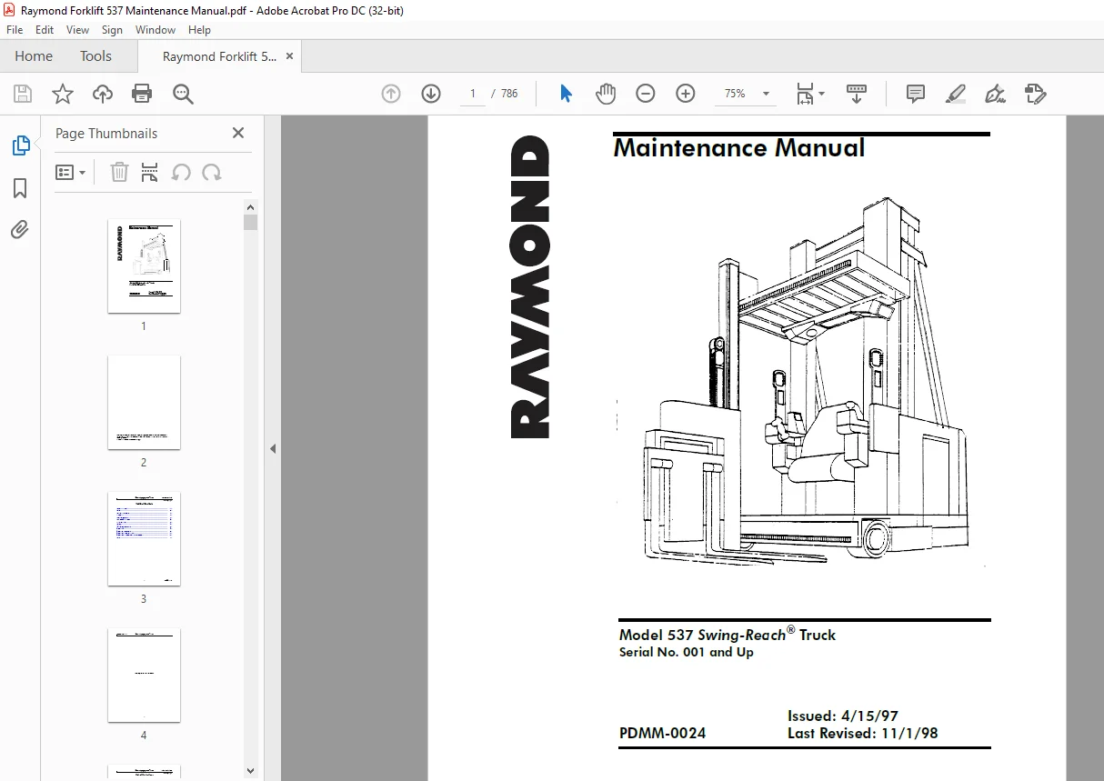
Raymond Forklift 537 Swing-Reach® Truck Maintenance Manual SN001 and Up – PDF DOWNLOAD
$34.95
Raymond Forklift 537 Swing-Reach® Truck Maintenance Manual SN001 and Up – PDF DOWNLOAD
Instant PDF Download
Available immediately
Save to Your Device
Download & keep forever
Antivirus Scanned
100% virus-free
Trusted Worldwide
175,000+ customers
Description
Raymond Forklift 537 Swing-Reach® Truck Maintenance Manual SN001 and Up – PDF DOWNLOAD
FILE DETAILS:
Raymond Forklift 537 Swing-Reach® Truck Maintenance Manual SN001 and Up – PDF DOWNLOAD
Language : English
Pages :786
Downloadable : Yes
File Type : PDF
Size:34.5 MB
DESCRIPTION:
Raymond Forklift 537 Swing-Reach® Truck Maintenance Manual SN001 and Up – PDF DOWNLOAD
General Information
Introduction
- This manual includes information required for maintenance, troubleshooting, and repair of the Model 537 Swing-Reach® truck. Other publications available for this vehicle are the Owner/Operator Manual, Technician’s Quick Reference Guide, and Parts Catalog.
- To gain the most benefit from the contents of this manual, review the entire contents to gain an overall understanding of the truck, then use the Table of Contents and/or Index to locate specific procedures and associated theory and descriptions. All information, specifications, and illustrations in this manual are based on the latest data available at the time of publication.
- The Raymond Corporation reserves the right to make changes or improvements at any time without notice.
General Safety
Industrial lift trucks may become hazardous if adequate maintenance is neglected. Only trained technicians, using approved procedures, in adequate maintenance facilities should work on this or any other lift truck.
1. Follow a scheduled lubrication, maintenance, and inspection schedule.
2. Only qualified, authorized technicians are permitted to inspect, maintain, adjust, and repair this vehicle.
TABLE OF CONTENTS:
Raymond Forklift 537 Swing-Reach® Truck Maintenance Manual SN001 and Up – PDF DOWNLOAD
General Information 1-1
Introduction 1-1
Special Tools Required 1-1
Common Tools Required 1-2
Fabricated Tools Required 1-2
Integrated Circuit Chip Replacement 1-2
Introduction 1-1
Special Tools Required 1-1
Common Tools Required 1-2
Fabricated Tools Required 1-2
Integrated Circuit Chip Replacement 1-2
General Information 1-1
Safety 2-1
Installation Instructions 3-1
Description 4-1
Theory of Operation 5-1
Scheduled Maintenance 6-1
Troubleshooting 7-1
Testing 8-1
Maintenance Procedures 9-1
Appendix A A-1
Appendix B – Schematics B-1
Appendix C – Inspection Schedule C-1
Appendix D – Troubleshooting Code Summary D-1
Index I-1
Figure 1-1: Removing Integrated Circuit Chip 1-3
Figure 1-2: Preparing Integrated Circuit Chip for Insertion 1-4
Figure 1-3: Integrated Circuit Chip/Socket Orientation 1-5
Figure 2-1: Correct Jacking Locations 2-4
Figure 2-2: Proper/Improper Method of Holding Circuit Board 2-5
Figure 2-3: Static Discharge Kit and Individual Components 2-7
Figure 3-1: Dimensions for the Wooden Blocks 3-2
Figure 3-2: Joining the Mast to the Tractor 3-4
Figure 3-3: Location of the Fork Pins, Fork Bar, and Setscrew 3-6
Figure 3-4: Bleed Locations 3-8
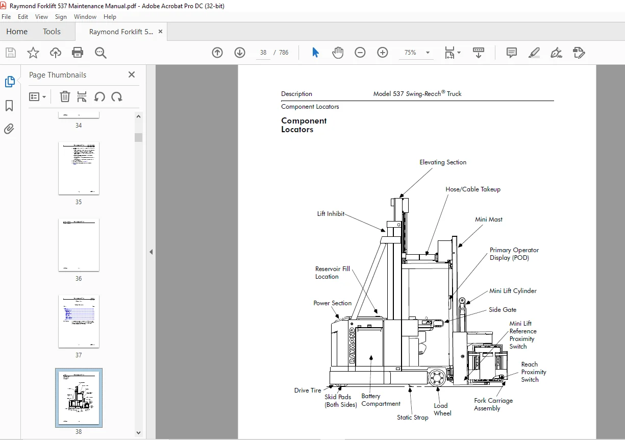
Figure 4-1: Component Locator 4-2
Figure 4-2: Component Locator 4-3
Figure 4-3: Component Locator 4-4
Figure 4-4: Component Locator 4-5
Figure 4-5: Component Locator 4-6
Figure 4-6: Component Locator 4-7
Figure 4-7: Component Locator 4-8
Figure 4-8: Component Locator 4-9
Figure 4-9: Component Locator 4-10
Figure 4-10: Component Locator 4-11
Figure 4-11: Component Locator 4-12
Figure 4-12: Component Locator 4-13
Figure 5-1: Systems Architecture 5-11
Figure 5-2: BUS+/BUS– Communication Signal 5-12
Figure 5-3: Hydraulic Schematic – Lift 5-21
Figure 5-4: Pulse Width Modulation Fast Lowering Rate 5-21
Figure 5-5: Pulse Width Modulation Slow Lowering Rate 5-22
Figure 5-6: Hydraulic Schematic – Lower 5-22
Figure 5-7: Lift/Lower Functional Block Diagram 5-23
Figure 5-8: Hydraulic Schematic – Mini Lift 5-26
Figure 5-9: Hydraulic Schematic – Mini Lower 5-27
Figure 5-10: Steering System Components 5-29
Figure 5-11: Card Cage Assembly (w/Electronic Steering & Wire Guidance) 5-31
Figure 5-12: Electronic Steering System Inputs/Outputs 5-32
Figure 5-13: Wire Guidance Portion of Secondary Operator’s Display 5-33
Figure 5-14: Electronic Steering Internal System Block Diagram 5-34
Figure 5-15: Deriving Sensor Position 5-39
Figure 5-16: Steering Modulator Output 5-45
Figure 5-17: Steering Pulse Width Modulation 5-45
Figure 5-18: Encoder X Signal 5-54
Figure 5-19: Steering Hose and Wiring Interconnections 5-55
Figure 5-21: Brake Release Switch S12 5-58
Figure 5-22: Brake Assembly Components 5-59
Running H/F 3
List of Illustrations Model 537 Swing-Reach® Truck
List of Illustrations
PDMM-0024 iv
Figure 5-23: Power Transistor Appearance 5-63
Figure 5-24: Power Transistor Electrical Symbol 5-64
Figure 5-25: Power Transistor Operation 5-65
Figure 5-26: Travel Circuit Functional Block Diagram 5-67
Figure 5-27: Power Amplifier Schematic 5-68
Figure 5-28: Field Transistor Module 5-84
Figure 5-29: H-Bridge Current Flow During Forks-First Travel 5-85
Figure 5-30: H-Bridge Current Flow Reverse, Tractor First 5-86
Figure 5-31: Schematic – Power Transistor OFF 5-87
Figure 5-32: Voltage Readings for 24-Volt Contactor Coil 5-88
Figure 5-33: Closed Loop Speed Control 5-90
Figure 5-34: Torque on Demand 5-91
Figure 5-35: Speed Reduction as Drive Motor Temperature Increases 5-92
Figure 5-36: Thermal Cut-Back 5-93
Figure 5-37: Current Limiting 5-93
Figure 5-38: Duty Cycle Comparison for Current Limiting 5-94
Figure 5-39: Hydraulic Schematic – Traverse 5-99
Figure 5-40: Hydraulic Schematic – Rotate 5-101
Figure 5-41: Hydraulic Schematic – Reach 5-103
Figure 6-1: Scheduled Maintenance Points 6-10
Figure 6-2: Power Section 6-11
Figure 6-3: Deadman Pedals 6-12
Figure 6-4: Example of Cleaning Motor 6-19
Figure 6-5: Measuring Brush Spring Tension 6-22
Figure 6-6: Lubrication Points on the EASi2 Swing-Reach® Vehicle 6-23
Figure 6-7: Lubrication Points on the EASi2 Swing-Reach® Truck Load Handler Section 6-24
Figure 6-8: Steering Ring Lubrication 6-25
Figure 6-9: Lubrication Points on the Drive Unit Gear Reducer 6-25
Figure 6-10: Lubrication Equivalency Chart 6-26
Figure 7-1: Secondary Operator’s Display (SOD) 7-25
Figure 7-2: Operator Display Showing a Password/SuperWrd
(Example Only) 7-25
Figure 7-3: Carriage or Vehicle Manager VFC indicating SuperWrd has been Entered 7-26
Figure 7-4: Carriage or Vehicle Manager VFC in Configure Mode after Password is Entered
7-27
Figure 7-5: Program Mode Menu Structure 7-28
Figure 7-6: VFC Shown in Learn Mode 7-29
Figure 7-7: VFC Shown in Maintenance Mode 7-32
Figure 7-8: Power Supply Card 7-122
Figure 7-9: Power Supply Card (Electronic Steer & W/G Vehicles) 7-122
Figure 7-10: Card Cage Layout 7-123
Figure 7-11: Adjusting Feedback Potentiometer 7-124
Figure 7-12: Solenoid Control Card 7-125
Figure 7-13: Logic Card ESTAT LEDs 7-126
Figure 7-14: Tolerance of a Centered Tire 7-127
Model 537 Swing-Reach® Truck List of Illustrations
List of Illustrations
v PDMM-0024
Figure 7-15: Wire Guidance Circuit Cards 7-130
Figure 7-16: Wire Guidance Alignment Box w/Adapter 7-130
Figure 7-17: Example of Alignment Track 7-132
Figure 7-18: Logic Card ESTAT LEDs 7-136
Figure 7-19: Electronic Steering/Wire Guidance Tester (P/N 114-005-807) 7-137
Figure 7-20: Electronic Steering/Wire Guidance Tester (P/N 114-005-807) 7-150
Figure 7-21: Digital Tester – Input Register 7-151
Figure 7-22: Digital Tester – Reference Register 7-152
Figure 7-23: Digital Tester – Deviation Register 7-153
Figure 7-24: Digital Tester – Control Register 7-154
Figure 7-25: Digital Tester – Error Register 7-155
Figure 7-26: Solenoid Controller Card Status Display 7-156
Figure 7-27: Solenoid Controller Card Status Display 7-160
Figure 7-28: Steering Demodulator Left/Right Turn Outputs 7-197
Figure 7-29: Modulated Steering Signal Output When Tiller is Not Being Rotated 7-198
Figure 7-30: Encoder X Signal 7-203
Figure 7-31: Checking Position Signal Polarities 7-211
Figure 7-32: Steering Hose and Wiring Interconnections 7-212
Figure 7-33: Chart Recorder Trace Showing Excessive Steering Effort 7-219
Figure 7-34: Chart Recorder Trace Showing Proper Steering Effort 7-219
Figure 7-35: Card Cage Circuit Card Arrangement 7-226
Figure 7-36: Adjusting Guidance Sensor 7-227
Figure 7-37: Coil Drivers on Carriage Manager 7-228
Figure 7-38: Schematic Heater Option 7-233
Figure 8-1: Pinout for JT2 8-51
Figure 8-2: Pinout for JH2 8-59
Figure 8-3: Guide Roller/End-of-Aisle Switch (S15) 8-77
Figure 8-4: Pinout for JH2 – “Forward HCM Enable” 8-95
Figure 8-5: Pinout for JH2 – “Reverse HCM Enable” 8-97
Figure 8-6: Horn Circuitry 8-103
Figure 8-7: Relay Socket 8-105
Figure 8-8: Pinout for JT2 – “Chopper Enable” 8-111
Figure 8-9: Logic Card ESTAT LEDs 8-119
Figure 8-10: SOD Locked-On Wire LEDs 8-129
Figure 8-11: Solenoid Controller Card Status Display 8-131
Figure 8-12: Test Points for Power Transistor Q1 8-174
Figure 8-12: Transistor Module For Field Wiring Assembly 8-176
Figure 8-13: HCM Test 8-177
Figure 8-14: REC1 Test 8-179
Figure 8-15: Vehicle Manager and Carriage Manager Power Supply Test Points 8-180
Figure 8-16: Motor Terminal – Proper Torque 8-182
Figure 8-17: Motor Terminals and Circuits 8-183
Figure 9-1: Power Supply 9-3
Figure 9-2: Solenoid Control Card 9-3
Figure 9-3: Steering Pressure Relief (Sheet 1 of 2) 9-4
List of Illustrations Model 537 Swing-Reach® Truck
List of Illustrations
PDMM-0024 vi
Figure 9-4: Steering Feedback Tachometer 9-6
Figure 9-5: Position Feedback Potentiometer 9-7
Figure 9-6: Drive Unit Removal/Installation Tool 9-9
Figure 9-7: Installation of Steer Motor and Torque Shaft 9-11
Figure 9-8: Drive Unit Servicing 9-12
Figure 9-9: Lower End of Drive Unit 9-14
Figure 9-10: Ring Gear Before Being Pressed Toward Flange 9-15
Figure 9-11: Ring Gear After Being Pressed Toward Flange 9-15
Figure 9-12: Removing Bearing Spacer Using Bearing Puller 9-16
Figure 9-13: Removing External Retaining Ring 9-16
Figure 9-14: Removing Output Shaft 9-17
Figure 9-15: Removal/Installation of Shaft Seal 9-17
Figure 9-16: Installing Ring Gear 9-18
Figure 9-17: Brake Assembly Components 9-19
Figure 9-18: Brake Shimming 9-20
Figure 9-19: Traverse Control Assembly 9-24
Figure 9-20: VR1 Potentiometer Wiring 9-25
Figure 9-21: Power Panel Assembly 9-27
Figure 9-22: Rail Switch Location 9-28
Figure 9-23: Rail Switch Detail (Viewed from bottom) 9-28
Figure 9-24: Auxiliary System Bleed Port – P1 9-30
Figure 9-25: Auxiliary Pressure Relief 9-31
Figure 9-26: Attaching Mast to Tractor 9-33
Figure 9-27: Decal Location Information (1 of 3) 9-34
Decal Location Information (2 of 3) 9-35
Decal Location Information (3 of 3) 9-36
Figure 9-28: Main Lift Pressure Relief 9-37
Figure 9-29: Auxiliary Pressure Relief 9-38
Figure 9-30: Mast Lateral Adjustment 9-39
Figure 9-31: Shimming Carriage Sliders 9-41
Figure 9-32: Operator’s Carriage Lateral Adjustment Locations 9-42
Figure 9-33: Operator’s Carriage Lateral Adjustment Device Cross Section 9-43
Figure 9-34: Mini Mast Cylinder Adjustment 9-44
Figure 9-35: Removing Mini Mast Stop Block 9-45
Figure 9-36: Shimming Top of Auxiliary Mast 9-45
Figure 9-37: Shimming Bottom of Auxiliary Mast 9-46
Figure 9-38: Shimming Traverse Shaft Support Bushing 9-47
Figure 9-39: PROX2 (Reach Position Reference) Adjustment on Fork Carriage 9-48
Figure 9-40: PROX1 (Mini Lift Reference) Adjustment on Mini Mast 9-49
Figure 9-41: Rack Replacement 9-50
Figure 9-42: Load Wheel Installation 9-51
Figure 9-43: Lift/Lower Potentiometer Replacement 9-52
Figure 9-44: Traverse Control Assembly 9-54
Figure 9-45: Control Potentiometer Wiring 9-55
Figure 9-46: Rotate Position Pot – VR6 9-56
Model 537 Swing-Reach® Truck List of Illustrations
List of Illustrations
vii PDMM-0024
Figure 9-47: Installing/Adjusting Traverse Potentiometer (VR5) 9-57
Figure 9-48: Hardware Securing Piston to Telescopic 9-59
Figure 9-49: Hardware Securing Cylinder Housing to Main Frame 9-59
Figure 9-50: Sheave/Pulley Assembly (Assembled and Exploded) 9-61
Figure 9-51: Placing Support Blocks Under Carriage 9-63
Figure 9-52: Positioning Railroad Jack Under Traverse Rack 9-63
Figure 9-53: Removing Upper Bearings and Roller Pins 9-64
Figure 9-54: Removing Auxiliary Lift Chain 9-66
Figure 9-55: Auxiliary Mast Assembly 9-66
Figure 9-56: Mini Mast Cylinder Pucks 9-67
Figure 9-57: Removing Mini Lift Chain 9-68
Figure 9-58: Mini Mast Assembly 9-69
Figure 9-59: Mini Mast Bearings 9-70
Figure 9-60: Cylinder Seal Installation Tools 9-72
Figure 9-61: Side View of an Installed Ram Support 9-73
Figure 9-62: Installing the Right Ram Support Rings 9-74
Figure 9-63: Installing the Left Ram Support 9-74
Figure 9-64: Conductive Seat Cover Replacement 9-75
Figure 9-65: Conductive Seat (Rear View) 9-76
Figure 9-66: Secondary Operator Display Shield Assembly 9-78
Figure 9-67: Tubing Guard Installation 9-79
Figure 9-68: Flow Sensor Assembly 9-80
Figure B-1: Electrical Schematic – Lift (Sheet 1 of 2) B-1
Electrical Schematic – Lift (Sheet 2 of 2) B-2
Figure B-2: Electrical Schematic – Lower (Sheet 1 of 2) B-3
Electrical Schematic – Lower (Sheet 2 of 2) B-4
Figure B-3: Electrical Schematic – Mini Lift (Sheet 1 of 2) B-5
Electrical Schematic – Mini Lift (Sheet 2 of 2) B-6
Figure B-4: Electrical Schematic – Mini Lower (Sheet 1 of 2) B-7
Electrical Schematic – Mini Lower (Sheet 2 of 2) B-8
Figure B-5: Brake Process Electrical Schematic (Sheet 1 of 2) B-9
Brake Process Electrical Schematic (Sheet 2 of 2) B-10
Figure B-6: Schematic – Battery Connected (Sheet 1 of 2) B-11
Schematic – Battery Connected (Sheet 2 of 2) B-12
Figure B-7: Power Distribution – Battery Connected B-13
Figure B-8: Schematic – Turning Keyswitch (S1) ON
(PC NOT ENERGIZED) (Sheet 1 of 3) B-14
Schematic – Turning Keyswitch (S1) ON
(PC NOT ENERGIZED) (Sheet 2 of 3) B-15
Schematic – Turning Keyswitch (S1) ON
(PC NOT ENERGIZED) (Sheet 3 of 3) B-16
Figure B-9: Power Distribution – Keyswitch Turned ON
(PC NOT ENERGIZED) B-17
Figure B-10: Schematic – Turning Keyswitch (S1) ON
(PC ENERGIZED) B-18
List of Illustrations Model 537 Swing-Reach® Truck
List of Illustrations
PDMM-0024 viii
Figure B-11: Power Distribution – Keyswitch Turned ON
(PC ENERGIZED) B-19
Figure B-12: Schematic – Closing Deadman Switches (S2/S25) (Sheet 1 of 3) B-20
Schematic – Closing Deadman Switches (S2/S25) (Sheet 2 of 3) B-21
Schematic – Closing Deadman Switches (S2/S25) (Sheet 3 of 3) B-22
Figure B-13: Power Distribution – Closing Deadman Switch (S25) B-23
Figure B-14: Schematic – Moving Directional/Speed Control to Forward B-24
Figure B-15: Schematic – Plugging B-25
Figure B-16: Electrical Schematic – Traverse (Sheet 1 of 2) B-26
Electrical Schematic – Traverse (Sheet 2 of 2) B-27
Figure B-17: Electrical Schematic – Rotate (Sheet 1 of 2) B-28
Electrical Schematic – Rotate (Sheet 2 of 2) B-29
Figure B-18: Electrical Schematic – Reach (Sheet 1 of 2) B-30
Electrical Schematic – Reach (Sheet 2 of 2) B-31
Figure B-19: Schematic – Rail Guidance (Sheet 1 of 3) B-32
Schematic – Rail Guidance (Sheet 2 of 3) B-33
Schematic – Rail Guidance (Sheet 3 of 3) B-34
Figure B-20: Schematic, Hydraulic B-35
Figure B-21: Schematic, Electrical (Sheet 1 of 5) B-36
Schematic, Electrical (Sheet 2 of 5) B-37
Schematic, Electrical (Sheet 3 of 5) B-38
Schematic, Electrical (Sheet 4 of 5) B-39
Schematic, Electrical (Sheet 5 of 5) B-40
Figure B-22: Revised Schematic Showing FU20/FU21 Installed / Second Travel Deadman
Switch (S25) Wiring B-41
Figure B-23: Schematic, Power Distribution B-42
Figure B-24: Test Connections, Interface Card B-43
Figure B-25: Test Connections, Filter Card Assembly B-44
Figure B-26: Test Connections, Interface Card B-45
Figure B-27: Test Connections, Logic Card Assembly B-46
Figure B-28: Test Connections, Power Panel Driver Card Assembly B-47
Figure B-29: Test Connections, Hydraulic Driver Card Assembly B-48
Figure B-30: Test Connections, Solenoid Controller Card Assembly B-49
Figure B-31: Test Connections, Processor Card Assembly B-50
Figure B-32: Test Connections, Motherboard B-51
Figure B-33: Electronic Steering Functional Block Diagram (Sheet 1 of 2) B-52
Electronic Steering Functional Block Diagram (Sheet 2 of 2) B-53
Model 537 Swing-Reach® Truck List of Tables
List of Tables
ix PDMM-0024
Table 5-1: Travel Circuit Components/Function 5-66
Table 6-1: Type of Service for Motors 6-21
Table 6-2: Inspection Frequency for Motors 6-21
Table 8-1: Causes of Motor Overheating 8-181
Table 9-1: Minimum Brush Lengths 9-8
Safety 2-1
Installation Instructions 3-1
Description 4-1
Theory of Operation 5-1
Scheduled Maintenance 6-1
Troubleshooting 7-1
Testing 8-1
Maintenance Procedures 9-1
Appendix A A-1
Appendix B – Schematics B-1
Appendix C – Inspection Schedule C-1
Appendix D – Troubleshooting Code Summary D-1
Index I-1
Figure 1-1: Removing Integrated Circuit Chip 1-3
Figure 1-2: Preparing Integrated Circuit Chip for Insertion 1-4
Figure 1-3: Integrated Circuit Chip/Socket Orientation 1-5
Figure 2-1: Correct Jacking Locations 2-4
Figure 2-2: Proper/Improper Method of Holding Circuit Board 2-5
Figure 2-3: Static Discharge Kit and Individual Components 2-7
Figure 3-1: Dimensions for the Wooden Blocks 3-2
Figure 3-2: Joining the Mast to the Tractor 3-4
Figure 3-3: Location of the Fork Pins, Fork Bar, and Setscrew 3-6
Figure 3-4: Bleed Locations 3-8
Figure 4-1: Component Locator 4-2
Figure 4-2: Component Locator 4-3
Figure 4-3: Component Locator 4-4
Figure 4-4: Component Locator 4-5
Figure 4-5: Component Locator 4-6
Figure 4-6: Component Locator 4-7
Figure 4-7: Component Locator 4-8
Figure 4-8: Component Locator 4-9
Figure 4-9: Component Locator 4-10
Figure 4-10: Component Locator 4-11
Figure 4-11: Component Locator 4-12
Figure 4-12: Component Locator 4-13
Figure 5-1: Systems Architecture 5-11
Figure 5-2: BUS+/BUS– Communication Signal 5-12
Figure 5-3: Hydraulic Schematic – Lift 5-21
Figure 5-4: Pulse Width Modulation Fast Lowering Rate 5-21
Figure 5-5: Pulse Width Modulation Slow Lowering Rate 5-22
Figure 5-6: Hydraulic Schematic – Lower 5-22
Figure 5-7: Lift/Lower Functional Block Diagram 5-23
Figure 5-8: Hydraulic Schematic – Mini Lift 5-26
Figure 5-9: Hydraulic Schematic – Mini Lower 5-27
Figure 5-10: Steering System Components 5-29
Figure 5-11: Card Cage Assembly (w/Electronic Steering & Wire Guidance) 5-31
Figure 5-12: Electronic Steering System Inputs/Outputs 5-32
Figure 5-13: Wire Guidance Portion of Secondary Operator’s Display 5-33
Figure 5-14: Electronic Steering Internal System Block Diagram 5-34
Figure 5-15: Deriving Sensor Position 5-39
Figure 5-16: Steering Modulator Output 5-45
Figure 5-17: Steering Pulse Width Modulation 5-45
Figure 5-18: Encoder X Signal 5-54
Figure 5-19: Steering Hose and Wiring Interconnections 5-55
Figure 5-21: Brake Release Switch S12 5-58
Figure 5-22: Brake Assembly Components 5-59
Running H/F 3
List of Illustrations Model 537 Swing-Reach® Truck
List of Illustrations
PDMM-0024 iv
Figure 5-23: Power Transistor Appearance 5-63
Figure 5-24: Power Transistor Electrical Symbol 5-64
Figure 5-25: Power Transistor Operation 5-65
Figure 5-26: Travel Circuit Functional Block Diagram 5-67
Figure 5-27: Power Amplifier Schematic 5-68
Figure 5-28: Field Transistor Module 5-84
Figure 5-29: H-Bridge Current Flow During Forks-First Travel 5-85
Figure 5-30: H-Bridge Current Flow Reverse, Tractor First 5-86
Figure 5-31: Schematic – Power Transistor OFF 5-87
Figure 5-32: Voltage Readings for 24-Volt Contactor Coil 5-88
Figure 5-33: Closed Loop Speed Control 5-90
Figure 5-34: Torque on Demand 5-91
Figure 5-35: Speed Reduction as Drive Motor Temperature Increases 5-92
Figure 5-36: Thermal Cut-Back 5-93
Figure 5-37: Current Limiting 5-93
Figure 5-38: Duty Cycle Comparison for Current Limiting 5-94
Figure 5-39: Hydraulic Schematic – Traverse 5-99
Figure 5-40: Hydraulic Schematic – Rotate 5-101
Figure 5-41: Hydraulic Schematic – Reach 5-103
Figure 6-1: Scheduled Maintenance Points 6-10
Figure 6-2: Power Section 6-11
Figure 6-3: Deadman Pedals 6-12
Figure 6-4: Example of Cleaning Motor 6-19
Figure 6-5: Measuring Brush Spring Tension 6-22
Figure 6-6: Lubrication Points on the EASi2 Swing-Reach® Vehicle 6-23
Figure 6-7: Lubrication Points on the EASi2 Swing-Reach® Truck Load Handler Section 6-24
Figure 6-8: Steering Ring Lubrication 6-25
Figure 6-9: Lubrication Points on the Drive Unit Gear Reducer 6-25
Figure 6-10: Lubrication Equivalency Chart 6-26
Figure 7-1: Secondary Operator’s Display (SOD) 7-25
Figure 7-2: Operator Display Showing a Password/SuperWrd
(Example Only) 7-25
Figure 7-3: Carriage or Vehicle Manager VFC indicating SuperWrd has been Entered 7-26
Figure 7-4: Carriage or Vehicle Manager VFC in Configure Mode after Password is Entered
7-27
Figure 7-5: Program Mode Menu Structure 7-28
Figure 7-6: VFC Shown in Learn Mode 7-29
Figure 7-7: VFC Shown in Maintenance Mode 7-32
Figure 7-8: Power Supply Card 7-122
Figure 7-9: Power Supply Card (Electronic Steer & W/G Vehicles) 7-122
Figure 7-10: Card Cage Layout 7-123
Figure 7-11: Adjusting Feedback Potentiometer 7-124
Figure 7-12: Solenoid Control Card 7-125
Figure 7-13: Logic Card ESTAT LEDs 7-126
Figure 7-14: Tolerance of a Centered Tire 7-127
Model 537 Swing-Reach® Truck List of Illustrations
List of Illustrations
v PDMM-0024
Figure 7-15: Wire Guidance Circuit Cards 7-130
Figure 7-16: Wire Guidance Alignment Box w/Adapter 7-130
Figure 7-17: Example of Alignment Track 7-132
Figure 7-18: Logic Card ESTAT LEDs 7-136
Figure 7-19: Electronic Steering/Wire Guidance Tester (P/N 114-005-807) 7-137
Figure 7-20: Electronic Steering/Wire Guidance Tester (P/N 114-005-807) 7-150
Figure 7-21: Digital Tester – Input Register 7-151
Figure 7-22: Digital Tester – Reference Register 7-152
Figure 7-23: Digital Tester – Deviation Register 7-153
Figure 7-24: Digital Tester – Control Register 7-154
Figure 7-25: Digital Tester – Error Register 7-155
Figure 7-26: Solenoid Controller Card Status Display 7-156
Figure 7-27: Solenoid Controller Card Status Display 7-160
Figure 7-28: Steering Demodulator Left/Right Turn Outputs 7-197
Figure 7-29: Modulated Steering Signal Output When Tiller is Not Being Rotated 7-198
Figure 7-30: Encoder X Signal 7-203
Figure 7-31: Checking Position Signal Polarities 7-211
Figure 7-32: Steering Hose and Wiring Interconnections 7-212
Figure 7-33: Chart Recorder Trace Showing Excessive Steering Effort 7-219
Figure 7-34: Chart Recorder Trace Showing Proper Steering Effort 7-219
Figure 7-35: Card Cage Circuit Card Arrangement 7-226
Figure 7-36: Adjusting Guidance Sensor 7-227
Figure 7-37: Coil Drivers on Carriage Manager 7-228
Figure 7-38: Schematic Heater Option 7-233
Figure 8-1: Pinout for JT2 8-51
Figure 8-2: Pinout for JH2 8-59
Figure 8-3: Guide Roller/End-of-Aisle Switch (S15) 8-77
Figure 8-4: Pinout for JH2 – “Forward HCM Enable” 8-95
Figure 8-5: Pinout for JH2 – “Reverse HCM Enable” 8-97
Figure 8-6: Horn Circuitry 8-103
Figure 8-7: Relay Socket 8-105
Figure 8-8: Pinout for JT2 – “Chopper Enable” 8-111
Figure 8-9: Logic Card ESTAT LEDs 8-119
Figure 8-10: SOD Locked-On Wire LEDs 8-129
Figure 8-11: Solenoid Controller Card Status Display 8-131
Figure 8-12: Test Points for Power Transistor Q1 8-174
Figure 8-12: Transistor Module For Field Wiring Assembly 8-176
Figure 8-13: HCM Test 8-177
Figure 8-14: REC1 Test 8-179
Figure 8-15: Vehicle Manager and Carriage Manager Power Supply Test Points 8-180
Figure 8-16: Motor Terminal – Proper Torque 8-182
Figure 8-17: Motor Terminals and Circuits 8-183
Figure 9-1: Power Supply 9-3
Figure 9-2: Solenoid Control Card 9-3
Figure 9-3: Steering Pressure Relief (Sheet 1 of 2) 9-4
List of Illustrations Model 537 Swing-Reach® Truck
List of Illustrations
PDMM-0024 vi
Figure 9-4: Steering Feedback Tachometer 9-6
Figure 9-5: Position Feedback Potentiometer 9-7
Figure 9-6: Drive Unit Removal/Installation Tool 9-9
Figure 9-7: Installation of Steer Motor and Torque Shaft 9-11
Figure 9-8: Drive Unit Servicing 9-12
Figure 9-9: Lower End of Drive Unit 9-14
Figure 9-10: Ring Gear Before Being Pressed Toward Flange 9-15
Figure 9-11: Ring Gear After Being Pressed Toward Flange 9-15
Figure 9-12: Removing Bearing Spacer Using Bearing Puller 9-16
Figure 9-13: Removing External Retaining Ring 9-16
Figure 9-14: Removing Output Shaft 9-17
Figure 9-15: Removal/Installation of Shaft Seal 9-17
Figure 9-16: Installing Ring Gear 9-18
Figure 9-17: Brake Assembly Components 9-19
Figure 9-18: Brake Shimming 9-20
Figure 9-19: Traverse Control Assembly 9-24
Figure 9-20: VR1 Potentiometer Wiring 9-25
Figure 9-21: Power Panel Assembly 9-27
Figure 9-22: Rail Switch Location 9-28
Figure 9-23: Rail Switch Detail (Viewed from bottom) 9-28
Figure 9-24: Auxiliary System Bleed Port – P1 9-30
Figure 9-25: Auxiliary Pressure Relief 9-31
Figure 9-26: Attaching Mast to Tractor 9-33
Figure 9-27: Decal Location Information (1 of 3) 9-34
Decal Location Information (2 of 3) 9-35
Decal Location Information (3 of 3) 9-36
Figure 9-28: Main Lift Pressure Relief 9-37
Figure 9-29: Auxiliary Pressure Relief 9-38
Figure 9-30: Mast Lateral Adjustment 9-39
Figure 9-31: Shimming Carriage Sliders 9-41
Figure 9-32: Operator’s Carriage Lateral Adjustment Locations 9-42
Figure 9-33: Operator’s Carriage Lateral Adjustment Device Cross Section 9-43
Figure 9-34: Mini Mast Cylinder Adjustment 9-44
Figure 9-35: Removing Mini Mast Stop Block 9-45
Figure 9-36: Shimming Top of Auxiliary Mast 9-45
Figure 9-37: Shimming Bottom of Auxiliary Mast 9-46
Figure 9-38: Shimming Traverse Shaft Support Bushing 9-47
Figure 9-39: PROX2 (Reach Position Reference) Adjustment on Fork Carriage 9-48
Figure 9-40: PROX1 (Mini Lift Reference) Adjustment on Mini Mast 9-49
Figure 9-41: Rack Replacement 9-50
Figure 9-42: Load Wheel Installation 9-51
Figure 9-43: Lift/Lower Potentiometer Replacement 9-52
Figure 9-44: Traverse Control Assembly 9-54
Figure 9-45: Control Potentiometer Wiring 9-55
Figure 9-46: Rotate Position Pot – VR6 9-56
Model 537 Swing-Reach® Truck List of Illustrations
List of Illustrations
vii PDMM-0024
Figure 9-47: Installing/Adjusting Traverse Potentiometer (VR5) 9-57
Figure 9-48: Hardware Securing Piston to Telescopic 9-59
Figure 9-49: Hardware Securing Cylinder Housing to Main Frame 9-59
Figure 9-50: Sheave/Pulley Assembly (Assembled and Exploded) 9-61
Figure 9-51: Placing Support Blocks Under Carriage 9-63
Figure 9-52: Positioning Railroad Jack Under Traverse Rack 9-63
Figure 9-53: Removing Upper Bearings and Roller Pins 9-64
Figure 9-54: Removing Auxiliary Lift Chain 9-66
Figure 9-55: Auxiliary Mast Assembly 9-66
Figure 9-56: Mini Mast Cylinder Pucks 9-67
Figure 9-57: Removing Mini Lift Chain 9-68
Figure 9-58: Mini Mast Assembly 9-69
Figure 9-59: Mini Mast Bearings 9-70
Figure 9-60: Cylinder Seal Installation Tools 9-72
Figure 9-61: Side View of an Installed Ram Support 9-73
Figure 9-62: Installing the Right Ram Support Rings 9-74
Figure 9-63: Installing the Left Ram Support 9-74
Figure 9-64: Conductive Seat Cover Replacement 9-75
Figure 9-65: Conductive Seat (Rear View) 9-76
Figure 9-66: Secondary Operator Display Shield Assembly 9-78
Figure 9-67: Tubing Guard Installation 9-79
Figure 9-68: Flow Sensor Assembly 9-80
Figure B-1: Electrical Schematic – Lift (Sheet 1 of 2) B-1
Electrical Schematic – Lift (Sheet 2 of 2) B-2
Figure B-2: Electrical Schematic – Lower (Sheet 1 of 2) B-3
Electrical Schematic – Lower (Sheet 2 of 2) B-4
Figure B-3: Electrical Schematic – Mini Lift (Sheet 1 of 2) B-5
Electrical Schematic – Mini Lift (Sheet 2 of 2) B-6
Figure B-4: Electrical Schematic – Mini Lower (Sheet 1 of 2) B-7
Electrical Schematic – Mini Lower (Sheet 2 of 2) B-8
Figure B-5: Brake Process Electrical Schematic (Sheet 1 of 2) B-9
Brake Process Electrical Schematic (Sheet 2 of 2) B-10
Figure B-6: Schematic – Battery Connected (Sheet 1 of 2) B-11
Schematic – Battery Connected (Sheet 2 of 2) B-12
Figure B-7: Power Distribution – Battery Connected B-13
Figure B-8: Schematic – Turning Keyswitch (S1) ON
(PC NOT ENERGIZED) (Sheet 1 of 3) B-14
Schematic – Turning Keyswitch (S1) ON
(PC NOT ENERGIZED) (Sheet 2 of 3) B-15
Schematic – Turning Keyswitch (S1) ON
(PC NOT ENERGIZED) (Sheet 3 of 3) B-16
Figure B-9: Power Distribution – Keyswitch Turned ON
(PC NOT ENERGIZED) B-17
Figure B-10: Schematic – Turning Keyswitch (S1) ON
(PC ENERGIZED) B-18
List of Illustrations Model 537 Swing-Reach® Truck
List of Illustrations
PDMM-0024 viii
Figure B-11: Power Distribution – Keyswitch Turned ON
(PC ENERGIZED) B-19
Figure B-12: Schematic – Closing Deadman Switches (S2/S25) (Sheet 1 of 3) B-20
Schematic – Closing Deadman Switches (S2/S25) (Sheet 2 of 3) B-21
Schematic – Closing Deadman Switches (S2/S25) (Sheet 3 of 3) B-22
Figure B-13: Power Distribution – Closing Deadman Switch (S25) B-23
Figure B-14: Schematic – Moving Directional/Speed Control to Forward B-24
Figure B-15: Schematic – Plugging B-25
Figure B-16: Electrical Schematic – Traverse (Sheet 1 of 2) B-26
Electrical Schematic – Traverse (Sheet 2 of 2) B-27
Figure B-17: Electrical Schematic – Rotate (Sheet 1 of 2) B-28
Electrical Schematic – Rotate (Sheet 2 of 2) B-29
Figure B-18: Electrical Schematic – Reach (Sheet 1 of 2) B-30
Electrical Schematic – Reach (Sheet 2 of 2) B-31
Figure B-19: Schematic – Rail Guidance (Sheet 1 of 3) B-32
Schematic – Rail Guidance (Sheet 2 of 3) B-33
Schematic – Rail Guidance (Sheet 3 of 3) B-34
Figure B-20: Schematic, Hydraulic B-35
Figure B-21: Schematic, Electrical (Sheet 1 of 5) B-36
Schematic, Electrical (Sheet 2 of 5) B-37
Schematic, Electrical (Sheet 3 of 5) B-38
Schematic, Electrical (Sheet 4 of 5) B-39
Schematic, Electrical (Sheet 5 of 5) B-40
Figure B-22: Revised Schematic Showing FU20/FU21 Installed / Second Travel Deadman
Switch (S25) Wiring B-41
Figure B-23: Schematic, Power Distribution B-42
Figure B-24: Test Connections, Interface Card B-43
Figure B-25: Test Connections, Filter Card Assembly B-44
Figure B-26: Test Connections, Interface Card B-45
Figure B-27: Test Connections, Logic Card Assembly B-46
Figure B-28: Test Connections, Power Panel Driver Card Assembly B-47
Figure B-29: Test Connections, Hydraulic Driver Card Assembly B-48
Figure B-30: Test Connections, Solenoid Controller Card Assembly B-49
Figure B-31: Test Connections, Processor Card Assembly B-50
Figure B-32: Test Connections, Motherboard B-51
Figure B-33: Electronic Steering Functional Block Diagram (Sheet 1 of 2) B-52
Electronic Steering Functional Block Diagram (Sheet 2 of 2) B-53
Model 537 Swing-Reach® Truck List of Tables
List of Tables
ix PDMM-0024
Table 5-1: Travel Circuit Components/Function 5-66
Table 6-1: Type of Service for Motors 6-21
Table 6-2: Inspection Frequency for Motors 6-21
Table 8-1: Causes of Motor Overheating 8-181
Table 9-1: Minimum Brush Lengths 9-8
IMAGES PREVIEW OF THE MANUAL:
Customer Support: [email protected]
https://vimeo.com/836421765?share=copy
PLEASE NOTE:
- This is the same manual used by the DEALERSHIPS to SERVICE your vehicle.
- The manual can be all yours – Once payment is complete, you will be taken to the download page from where you can download the manual. All in 2-5 minutes time!!
- Need any other service / repair / parts manual, please feel free to contact us at heydownloadss @gmail.com . We may surprise you with a nice offer
S.M