Raymond Forklift 7200 7300 7310 Reach-Fork® Trucks Parts Manual 101 & up – PDF DOWNLOAD
$25.95
Raymond Forklift 7200 7300 7310 Reach-Fork® Trucks Parts Manual 101 & up – PDF DOWNLOAD
Description
Raymond Forklift 7200 7300 7310 Reach-Fork® Trucks Parts Manual 101 & up – PDF DOWNLOAD
FILE DETAILS:
Raymond Forklift 7200 7300 7310 Reach-Fork® Trucks Parts Manual 101 & up – PDF DOWNLOAD
Language : English
Pages :682
Downloadable : Yes
File Type : PDF
Size:114 MB
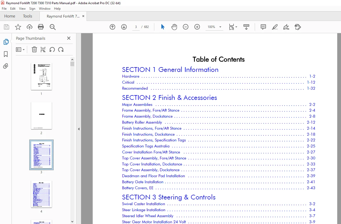
TABLE OF CONTENTS:
Raymond Forklift 7200 7300 7310 Reach-Fork® Trucks Parts Manual 101 & up – PDF DOWNLOAD
SECTION 1 General Information
Hardware 1-2
Critical 1-12
Recommended 1-32
SECTION 2 Finish & Accessories
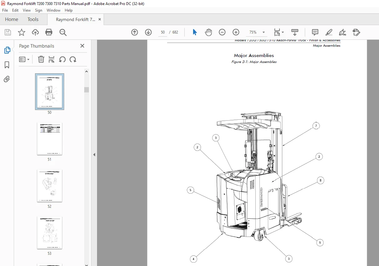
Major Assemblies 2-2
Frame Assembly, Fore/Aft Stance 2-4
Frame Assembly, Dockstance 2-8
Battery Roller Assembly 2-12
Finish Instructions, Fore/Aft Stance 2-14
Finish Instructions, Dockstance 2-18
Finish Instructions, Specification Tags 2-22
Specification Tags Australia 2-25
Cover Installation Fore/Aft Stance 2-27
Top Cover Assembly, Fore/Aft Stance 2-30
Top Cover Installation, Dockstance 2-33
Top Cover Assembly, Dockstance 2-37
Deadman and Floor Pad Installation 2-39
Battery Gate Installation 2-41
Battery Covers, EE 2-43
SECTION 3 Steering & Controls
Swivel Caster Installation 3-2
Steer Linkage Installation 3-4
Steered Idler Wheel Assembly 3-7
Steer Gear Motor Installation 24 Volt 3-9
Steer Motor Assembly 24 Volt 3-11
Steer Motor Installation 36 Volt 3-13
Steer Motor Assembly 36 Volt 3-16
Steering Wheel Installation, Fore/Aft Stance 3-18
Steering Wheel Assembly Fore/Aft Stance 3-20
Steering Wheel Assembly, Fore/Aft Stance, AC Lift 3-22
Steering Wheel Installation, Dockstance 3-24
Steering Wheel Assembly, Dockstance 3-26
Control Handle Bracket Weldment 3-28
Control Handle Installation 3-30
Control Handle Assembly, Fore/Aft Stance 3-32
Control Handle Assembly, Fore/Aft Stance, ThermaKit 3-37
Control Handle Assembly, Dockstance 3-40
Control Handle Assembly, Dockstance, ThermaKit 3-42
Control Assembly Installation 3-46
Drive Unit Installation 4-2
Traction Motor Installation 4-4
Drive Unit Assembly 4-6
Brake Installation 4-9
Brake Assembly Electric 4-11
Deadman Pedal Installation 4-13
Deadman Pedal Assembly 4-15
Drive Wheel Installation 4-17
Inertial Dampener Installation 4-19
SECTION 5 Electrical Comp. & System
Electrical System, 7200, Fore/Aft Stance, 24 Volt 5-2
Electrical System, 7300, 7310 Fore/Aft Stance, 36 Volt 5-7
Electrical System, 7200, Dockstance, 24 Volt 5-12
Electrical System, 7300, Dockstance, 36 Volt 5-17
Traction Power Amplifier Installation 5-22
Traction Power Amplifier Assembly 24 Volt 5-25
Traction Power Amplifier Assembly 36 Volt 5-27
Lift Power Amplifier Installation 5-29
Lift Power Amplifier Assembly 24 Volt 5-32
Lift Power Amplifier Assembly 36 Volt 5-34
Vehicle Manager Installation 5-36
Contactor Panel Installation 5-38
Contactor Panel Assembly 5-41
Contactor Panel Assembly, EE 5-44
Contactor Assembly 5-46
Drive Motor Assembly (E) 5-48
Drive Motor 36 Volt EE With Encoder Bearing 5-50
Drive Motor Assembly (EE) 5-52
Lift Motor Assembly (E) 5-54
Lift Motor Assembly (EE) 5-56
7 in. Evolution Display Installation – 3001 Up 5-58
Dash Panel Installation, Fore/Aft Stance – S/N 3001 Up 5-61
Operator Display Installation, Fore/Aft Stance – Below S/N 3001 5-63
Dash Panel Installation, Dockstance – S/N 3001 Up 5-66
Operator Display Installation, Dockstance – Below S/N 3001 5-68
Horn Assembly 5-71
Key Switch Installation 5-74
Relay/Control Fuse Panel Installation with Auxiliary Power 5-76
Fuse Relay Circuit With Aux Power 5-80
Battery Connector Installation 5-82
Battery Connector Assembly 5-84
Height Sensing Encoder Installation 5-86
Height Sensing Encoder Assembly 5-90
Height Sensor Heater Installation 5-92
Travel/Lift Limit Switch Installation 5-94
Ambient Temperature Sensor Installation 5-99
Fan Assembly, Lift Motor Compartment 5-101
Fan Assembly, Drive Motor Compartment 5-103
SECTION 6 Hydraulic Components
Hose Installation, All 6-2
Manifold Installation 6-4
Manifold Assembly 6-6
Manifold Assembly, Reach, R35TT and R4XTT 6-10
Manifold Assembly, Reach, Deep Reach 6-12
Manifold Assembly, Tilt and Sideshift, DRTT 6-14
Manifold Assembly, Tilt, DRTT 6-16
Manifold Assembly 4D 6-18
Reservoir Installation 6-20
Reservoir Assembly 6-22
Lift Pump and Motor Installation 6-24
Lift Pump and Motor Assembly 6-26
Main Lift Cylinder R4XTT, DRTT 6-29
Main Lift Cylinder R35TT 6-33
Free Lift Cylinder Assemblies R.H. & L.H. 6-36
Reach Cylinder Assembly 6-39
Tilt Cylinder Assembly 6-41
Sideshift Cylinder Assembly 6-43
4D Steer Cylinder Assembly 6-45
SECTION 7 Mast
Mast to Tractor Mounting 7-3
Elevating Section R35TT 7-5
Main Lift Cylinder Installation (R35TT) 7-11
Elevating Section R4XTT and DRTT 7-14
Main Lift Cylinder Installation R4XTT, DRTT 7-24
Free Lift Chain Installation 7-27
Free Lift Cylinder Installation, All 7-32
Main Lift Hose Assembly (Over the Mast) 7-34
Over the Mast Hose and Cable Installation 7-36
Carriage Installation, R35TT and R4XTT 7-51
Reach Carriage Assembly R35TT and R4XTT 7-53
Scissor Assembly, R35TT and R4XTT 7-59
Carriage Installation DRTT 7-61
Reach Carriage Assembly, DRTT 7-64
Scissor Assembly, Deep Reach, DRTT 7-69
Hose and Cable Installation R35TT and R4XTT 7-73
Hose and Cable Installation, Carriage, DRTT 7-77
Carriage Assembly, Tilt without Sideshift, R35TT and R4XTT 7-80
Carriage Assembly, Tilt and Sideshift, R35TT and R4XTT 7-82
Carriage Subassembly, Tilt and Sideshift, R35TT and R4XTT 7-85
Carriage Assembly, Tilt without Sideshift, DRTT 7-87
Carriage Assembly, Tilt and Sideshift, DRTT 7-89
Carriage Sub Assembly, Sideshift, DRTT 7-91
Carriage Assembly, Tilt W/WO Sideshift (4D) 7-93
Hang On Sideshift Carriage, 4D 7-96
Overhead Guard Installation 7-98
Mast Guard Installation, Mesh 7-100
Mast Guard Installation, Glass 7-102
Baseleg Installation, R35TT, 5 x 3.62 in. and 10 x 4.5 in., Open Toe 7-105
Baseleg Installation, R35TT, 5 x 3.62 in., Closed Toe 7-107
Baseleg Installation, R35TT, 5 x 2.88 in., Open Toe 7-109
Baseleg Installation, R35TT, 5 x 2.88 in., Closed Toe 7-111
Baseleg Installation, R35TT, 4 x 3.62 in., Closed Toe 7-113
Baseleg Installation, R35TT, 4 x 2.88 in. Closed Toe 7-115
Baseleg Installation, R4XTT, 5 x 3.62 in. and 10 X 4.5 in., Open Toe 7-117
Baseleg Installation, R4XTT, 5 x 3.62 in., Closed Toe 7-119
Baseleg Installation, R4XTT, 5 x 2.88 in., Open Toe 7-121
Baseleg Installation, R4XTT, 5 x 2.88 in., Closed Toe 7-123
Baseleg Installation, R4XTT, 4 x 3.62 in., Closed Toe 7-125
Baseleg Installation, R4XTT, 4 x 2.88 in., Closed Toe 7-127
Baseleg Installation, DRTT, 5 x 3.62 in. Closed Toe 7-129
Baseleg Installation, DRTT, 5 x 2.88 in., Closed Toe 7-131
Baseleg Installation, DRTT, 4 x 3.62 in., Closed Toe 7-133
Baseleg Installation, DRTT, 4 x 2.88 in., Closed Toe 7-135
Wheel Plate Installation, Open Toe, 5 x 3.62 in. 7-137
Wheel Plate Installation, Open Toe, 5 x 2.88 in. 7-139
Wheel Plate Installation, Open Toe, 10 x 4.50 in. 7-141
Wheel Plate Installation, 5 X 3.62 in., Closed Toe 7-145
Wheel Plate Installation, 5 X 2.88 in., Closed Toe 7-147
Wheel Plate Installation, 4 X 3.62 in., Closed Toe 7-149
Wheel Plate Installation, 4 X 2.88 in., Closed Toe 7-151
Wheel Plate Installation, OWCTWB, 5 x 3.62 in., 5 x 2.88 in., 4 x 3.62 in. 7-153
Load Wheel Assembly 7-155
4D Load Wheel, Caster Installation 7-158
4D Caster Hose and Cable Installation 7-160
Carriage Stop Assembly 7-163
Stop Assembly, Inner Telescopic 7-165
Stop Assembly, Sideshift 7-168
Forks 7-170
SECTION 8 Options & Kits
Security Start Switch 8-2
Load Backrest Installation 8-4
Auxiliary Light Installation 8-7
Strobe Light Installation 8-9
Travel Light and Alarm Installation 8-12
Travel Alarm Installation 8-17
Light Assembly, LED 8-19
Travel Light and Fan Installation (LED) 8-21
Fan Assembly, Operator Cooling 8-23
Light Assembly, LED 8-25
Rear Door Installation, Fore/Aft Stance 8-27
Rear Door Installation, Dockstance 8-29
Rear Post, Guard, Fore/Aft Stance 8-31
Rear Post, Guard, Fore/Aft Stance, 4D Only 8-34
Rear Post, Guard, Dockstance 8-37
Auxiliary Carriage – 4D 8-39
Overhead Guard Covers 8-42
Operator Backrest Extension, Dockstance 8-45
Fire Extinquisher Installation 8-47
Operator Compartment Sensor System (OCSS), Fore/Aft Stance 8-49
Operator Compartment Sensor System (OCSS), Dockstance 8-52
Height-Tilt Indicator Display Installation 8-55
Tilt Carriage Shims 8-57
Sideshift Fitting-Guard Installation 8-60
Nested Switch (S14) Installation, Standard Reach 8-62
Nested Switch (S14) Installation, Deep-Reach 8-64
Vantage Point System 8-67
iPort Installation 8-73
iWarehouse RED 8-74
Battery Gate Interlock Installation 8-76
Fork-Laser System, Installation 8-78
RF Adjustable Linkage Installation 8-83
High Speed Lift Cut Out 24 inch 8-86
Dome Light Installation 8-88
Dome Light Assembly 8-90
APPENDIX A Alphabetical Parts Index
APPENDIX B Numerical Parts Index
IMAGES PREVIEW OF THE MANUAL:
Need help? Contact: [email protected]
https://vimeo.com/837294311?share=copy
PLEASE NOTE:
- This is the SAME manual used by the dealers to troubleshoot any faults in your vehicle. This can be yours in 2 minutes after the payment is made.
- Contact us at [email protected] should you have any queries before your purchase or that you need any other service / repair / parts operators manual.
S.M