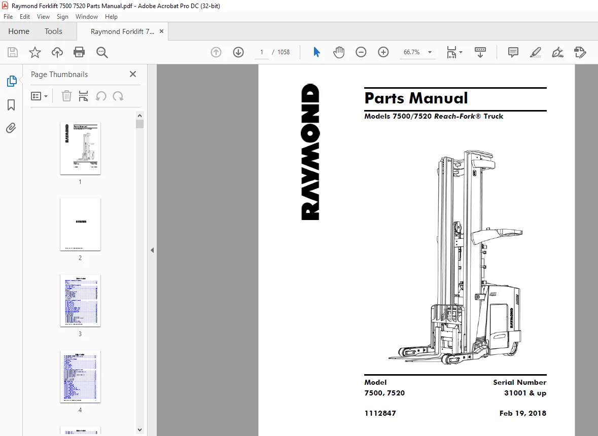
Raymond Forklift 7500 7520 Reach-Fork® Truck Parts Manual 1112847 – PDF DOWNLOAD
$33.95
Raymond Forklift 7500 7520 Reach-Fork® Truck Parts Manual 1112847 – PDF DOWNLOAD
Description
Raymond Forklift 7500 7520 Reach-Fork® Truck Parts Manual 1112847 – PDF DOWNLOAD
FILE DETAILS:
Raymond Forklift 7500 7520 Reach-Fork® Truck Parts Manual 1112847 – PDF DOWNLOAD
Language : English
Pages :1058
Downloadable : Yes
File Type : PDF
Size:159 MB
TABLE OF CONTENTS:
Raymond Forklift 7500 7520 Reach-Fork® Truck Parts Manual 1112847 – PDF DOWNLOAD
SECTION 1 General Information
Hardware 1-2
Critical 1-17
Recommended 1-62
SECTION 2 Finish & Accessories
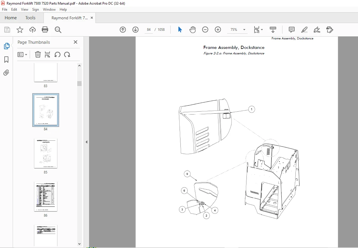
Frame Assembly, Dockstance 2-2
Frame Assembly, Fore/Aft Stance 2-6
Battery Spacer, Adjuster 2-10
Battery Roller Assembly 2-12
Finish Instructions 2-14
Finish Intructions 2-22
Tractor Cover Installation, Fore/Aft Stance 2-32
Top Cover Assembly, Fore/Aft Stance 2-40
Tractor Cover Installation, Dockstance 2-43
Top Cover Assembly, Dockstance 2-48
Deadman and Floor Pad Installation 2-50
Battery Cover Installation, Steel Set 2-52
Battery Gate Installation 2-54
Battery Covers, EE 2-57
SECTION 3 Steering & Controls
Steer Linkage Installation 3-2
Steered Idler Wheel Assembly 3-6
Steer Motor Installation, DC Lift 3-8
Steer Motor Assembly, DC Lift 3-11
Steer Motor Installation, AC Lift 3-13
Steer Motor Assembly, AC Lift 3-16
Steering Wheel Installation, Fore/Aft Stance, DC Lift 3-18
Steering Wheel Installation, Fore/Aft Stance, AC Lift 3-21
Steering Wheel Assembly, Fore/Aft Stance, AC Lift 3-23
Steering Wheel Installation, Dockstance, DC Lift 3-25
Steering Wheel Installation, Dockstance, AC Lift 3-27
Steering Wheel Assembly, Dockstance, AC Lift 3-29
Steering Tiller Assembly DS 3-31
Steering Wheel Assembly DS 3-33
Control Handle Installation 3-35
Bracket Handle, Weldment 3-37
Control Handle Assembly, Fore/Aft Stance, Primary 3-39
Control Handle Assembly, Fore/Aft Stance, Primary, ThermaKit 3-44
Control Handle Assembly, Dockstance 3-48
Control Handle Assembly, Dockstance 3-53
Control Handle Assembly, Dockstance, Thermakit 3-57
Control Handle Installation, Fore/Aft Stance, Secondary 3-62
Control Handle Assembly, Fore/Aft Stance, Secondary 3-64
Control Handle Assembly, Fore/Aft Stance, Secondary, ThermaKit 3-66
Control Assembly Installation 3-69
SECTION 4 Drive & Brake
Drive Unit Installation 4-2
Traction Motor Installation 4-4
Drive Unit Assembly 4-6
Brake Installation 4-9
Brake Assembly, Electric 4-11
Deadman Pedal Installation 4-13
Pedal Assembly, Deadman 4-15
Drive Wheel Installation 4-17
Inertial Dampener Installation 4-19
SECTION 5 Electrical Comp. & System
Electrical System, Fore/Aft Stance With Regen 5-3
Electrical System, Fore/Aft Stance With Regen, Serial Number 60,001 and up 5-7
Electrical System, Fore/Aft Stance AC Lift 5-13
Electrical System, Fore/Aft Stance DC Lift 5-17
Electrical System, Dockstance With Regen, Serial Number 60,001 and up 5-20
Electrical System, Dockstance With Regen 5-25
Electrical System, Dockstance, AC Lift 5-30
Electrical System 5-34
Traction Power Amplifier Installation 5-37
Traction Power Amplifier Assembly 5-39
Lift Power Amplifier Installation 5-41
Lift Power Amplifier Assembly 5-43
Auxiliary Controller Installation 5-45
Vehicle Manager Installation 5-47
Contactor Panel Installation (STD) 5-49
Contactor Panel Assembly (DC Lift) 5-51
Contactor Panel Assembly (AC Lift) 5-53
Contactor Panel Installation Regen Lower Only 5-56
Contactor Panel Assembly Regen Lower Only 5-58
Contactor Panel Assembly Regen Lower With AC Auxiliary 5-61
Contactor Panel Installation (EE) 5-64
Contactor Panel Assembly, EE, (DC Lift) 5-66
Contactor Panel Assembly, EE, (AC Lift) 5-68
Contactor Panel Installation, EE, Regen Lower Only 5-70
Contactor Panel Assembly, EE, Regen Lower Only 5-72
Contactor Assembly, Aux and Steer 5-74
Drive Motor Assembly 5-76
Lift Motor Assembly, DC 5-79
Lift Motor Assembly, AC 5-81
Auxiliary Motor Assembly 5-83
Auxiliary Motor Assembly 5-85
Auxiliary Motor Assembly, AC 5-87
7 in. Evolution Display Installation – S/N 65001 Up 5-89
Operator Display Installation, Fore/Aft Stance, Below S/N 65001 5-92
Dash Panel Installation, Fore/Aft Stance – S/N 65001 Up 5-94
Operator Display Installation, Dockstance, Below S/N 65001 5-96
Dash Panel Installation, Dockstance – S/N 65001 Up (AC/Regen) 5-99
Display Installation 5-101
Horn Installation 5-103
Switch Assembly, Key 5-106
Relay/Control Fuse Panel Installation with Auxiliary Power 5-108
Fuse/Relay Card With Aux Power 5-112
Battery Connector Installation 5-114
Battery Connector Installation, EURO 5-116
Battery Connector Assembly 5-118
Battery Connector Euro Pigtail 5-121
Height Encoder Installation Model 7500 5-123
Encoder Assembly, Height Indicator 5-127
Guard-Height Sensing Installation 5-129
Height Encoder Installation Model 7520 5-131
Encoder Assembly, Height Indicator Model 7520 5-133
Encoder Heater Installation 5-135
Limit Switch Installation, High Speed, End of Lift 5-137
Ambient Temperature Sensor Installation 5-139
Fan Assembly, Drive Motor Compartment 5-141
Fan Assembly, Lift Motor Compartment 5-143
Speed Limiting Switch (S12) Installation 5-145
SECTION 6 Hydraulic Components
Hose Installation, Dockstance, DC Lift 6-2
Hose Installation, Fore/Aft Stance, DC Lift 6-4
Hose Installation, Dockstance, AC Lift 6-6
Hose Installation, Fore/Aft Stance, AC Lift 6-8
Hose Installation, Dockstance, AC Lift With Regen 6-10
Hose Installation, Dockstance, AC Lift With Regen, Serial Number 60001 and up 6-13
Hose Installation, Fore/Aft Stance, AC Lift With Regen 6-16
Hose Installation, Fore/Aft Stance, AC Lift With Regen, Serial Number 60001 and up 6-18
Reservoir Installation, AC Lift 6-21
Reservoir Assembly, AC Lift 6-23
Reservoir Installation, DC Lift 6-25
Reservoir Assembly, DC Lift 6-27
Lift Pump and Motor Installation, DC Lift 6-29
Lift Pump and Motor Installation, AC Lift 6-33
Lift Pump and Motor Assembly AC Lift 6-35
Lift Pump and Motor Installation With Regen 6-37
Lift Pump and Motor Assembly With Regen 6-39
Auxiliary Pump and Motor Installation, Dockstance 6-41
Auxiliary Pump and Motor Installation, Fore and Aft Stance 6-43
A.C. Auxiliary Pump and Motor Installation 6-45
Auxiliary Pump and Motor Assembly 6-47
Auxiliary Pump and Motor Assembly, Serial Number 60001 and up 6-49
Lift Pump Assembly, DC Single 6-51
Lift Pump Assembly, DC, Dual 6-53
Lift Pump Manifold Assembly, Regen 6-55
Auxiliary Pump 6-57
Auxiliary Pump Assembly, Serial Number 60001 and up 6-59
Main Manifold Installation, DC Lift 6-61
Main Manifold Assembly, DC Lift 6-63
Main Manifold Installation, AC Lift 6-67
Manifold Assembly 6-69
Main Manifold Installation (Regen Only) 6-72
Manifold Assembly, Lift/Lower (Regen Only) 6-74
Auxiliary Manifold Installation With Regen 6-76
Auxiliary Manifold Installation With Regen, Serial Number 60001 and up 6-78
Manifold Assembly, Auxiliary, With Regen 6-80
Auxiliary Manifold Assembly, Serial Number 60001 and up 6-82
Manifold Assembly, Reach, Tilt and Sideshift, R35TT and R45TT 6-84
Manifold Assembly, Reach, DR32TT 6-86
Manifold Assembly, Tilt, DR32TT 6-88
Manifold Assembly, Tilt and Sideshift 6-90
Cylinder Assembly, Main Lift, 7500 6-92
Cylinder Assembly, Main Lift 7520 6-94
Cylinder Assembly, Free Lift, Non-Staging (DC Lift), R35TT 6-96
Cylinder Assembly, Free Lift, Staging, (AC Lift) R35TT, R45TT and DR32TT 6-98
Cylinder Assembly, Free Lift (AC Lift), Model 7520 6-101
Cylinder Assembly, Reach 6-104
Cylinder Assembly, Reach 6-107
Cylinder Assembly, Tilt 6-109
Cylinder Assembly, Tilt 6-111
Cylinder Assembly, Sideshift 6-113
Cylinder Assembly, Sideshift 6-115
SECTION 7 Mast
Mast to Tractor Mounting, 7500 7-3
Mast to Tractor Mounting, 7520 7-5
Elevating Section R35TT 7-7
Main Lift Cylinder Installation (R35TT) 7-13
Elevating Section R45TT and DR32TT (Model 7500) 7-16
Main Lift Cylinder Installation R45TT, DR32TT 7-26
Elevating Section, R45TT and DR32TT (Model 7520) 7-29
Main Lift Cylinder Installation, R45TT and DR32TT (Model 7520) 7-37
Free Lift Chain Installation 7-39
Free Lift Cylinder Installation (R35TT DC Lift) 7-55
Free Lift Cylinder Installation, 7500 (R35TT, R45TT AC Lift) 7-57
Free Lift Cylinder Installation 7500 (DR32TT AC Lift) 7-59
Free Lift Cylinder Installation, 7500 (R35TT, R45TT AC Lift) 7-62
Cylinder and Pulley Bracket Assembly, Free Lift (Model 7520) 7-64
Overhead Guard Installation 7-66
Main Lift Hose Assembly (Over The Mast) 7-68
Lift Hose Installation, Drive In Rack (Over The Mast) 7-70
Over The Mast Hose and Cable Installation (7500) R35TT, R45TT, DR32TT 7-75
Over The Mast Hose and Cable Installation (7520) R45TT and DR32TT 7-90
Over the Mast Hose and Cable Installation, 7520 (Drive in Rack) 7-108
Carriage Installation, R35TT and R45TT 7-122
Reach Carriage Assembly, R35TT and R45TT 7-125
Scissor Assembly, R35TT and R45TT 7-132
Carriage Installation, DR32TT 7-134
Reach Carriage Assembly, DR32TT 7-137
Scissor Assembly, Deep Reach, DR32TT 7-143
Hose and Cable Installation, Carriage, R35TT and R45TT 7-148
Hose and Cable Installation, Carriage, DR32TT 7-152
Hose and Cable Assembly, Carriage, 7520, DR32TT, (Drive-In Rack) 7-155
Carriage Assembly, Tilt without Sideshift, R35TT and R45TT 7-158
Carriage Assembly, Tilt and Sideshift, R35TT and R45TT 7-160
Tilt and Sideshift Piping, 7520, R45TT (Drive-In Rack) 7-163
Carriage Subassembly, Tilt and Sideshift, R35TT and R45TT 7-165
Carriage Assembly, Tilt without Sideshift, DR32TT 7-167
Carriage Assembly, Tilt without Sideshift, R45TT (Drive-In Rack) 7-169
Carriage Assembly, Tilt and Sideshift, DR32TT 7-171
Carriage Sub Assembly, Sideshift, DR32TT 7-174
Carriage Assembly, Sideshift, Bolzoni 7-176
Mast Guard Installation, Mesh 7-178
Mast Guard Installation, Glass 7-181
Baseleg Installation, R35TT, 5 x 3.62 in., Open Toe 7-184
Baseleg Installation, R35TT, 5 x 3.62 in., Straddle Closed Toe 7-186
Baseleg Installation, R35TT, 5 x 2.88 in., Open Toe 7-188
Baseleg Installation, R35TT, 5 x 2.88 in., Straddle Closed Toe 7-190
Baseleg Installation, R35TT, 4 x 3.62 in., Closed Toe 7-192
Baseleg Installation, R35TT, 4 x 2.88 in., Closed Toe 7-194
Baseleg Installation, R45TT, 5 x 3.62 in., Open Toe 7-196
Baseleg Installation, R45TT, 5 x 3.62 in., Closed Toe 7-198
Baseleg Installation, R45TT, 5 x 2.88 in., Open Toe 7-200
Baseleg Installation, R45TT, 5 x 2.88 in., Closed Toe 7-202
Baseleg Installation, R45TT, 4 x 3.62 in., Closed Toe 7-204
Baseleg Installation, R45TT, 4 x 2.88 in., Closed Toe 7-206
Baseleg Installation, DR32TT, 5 x 3.62 in., Closed Toe 7-208
Baseleg Installation, DR32TT, 5 x 2.88 in., Closed Toe 7-210
Baseleg Installation, DR32TT, 4 x 3.62 in., Closed Toe 7-212
Baseleg Installation, DR32TT, 4 x 2.88 in., Closed Toe 7-214
Baseleg Installation, R45TT, 6 x 4 in., Open Toe (Model 7520) 7-216
Baseleg Installation, 6 x 2.88 in. 7-218
Baseleg Installation, R45TT, 6 x 4 in., Closed Toe (Model 7520) 7-220
Baseleg Installation, 5 x 3.62 in., Closed Toe (Model 7520) 7-222
Wheel Plate Installation, Open Toe, 5 x 3.62 in. 7-224
Wheel Plate Installation, 6 x 4 in., Open Toe 7-226
Wheel Plate Installation, 10.5 x 4.5 in., Open Toe 7-228
Wheel Plate Installation, Closed Toe, Cast (All Except 6 x 4 in.) 7-232
Wheel Plate Installation, Closed Toe, Cast (6 x 4 in.) 7-236
Wheel Plate Installation, OWCTWB, 5 x 3.62 in. and 5 x 2.88 in., 6 x 2.88 in. 7-238
Load Wheel Assembly 7-241
Stop Assembly 7-245
Stop Assembly, Sideshift 7-247
Stop Assembly, Carriage 7-249
Forks 7-251
SECTION 8 Options & Kits
Load Backrest Installation 8-2
Rear Door Installation, Fore/Aft Stance 8-5
Rear Door Installation, Dockstance 8-7
Fire Extinguisher Installation 8-9
Rear Post, Guard, Fore/Aft Stance 8-11
Rear Post and Operator Backrest Installation, Dockstance 8-13
Overhead Guard Covers 8-15
Nested Switch (S14) Installation, Standard Reach 8-17
Nested Switch (S14) Installation, Deep-Reach 8-19
Vantage Point System 8-22
Security Start Switch 8-29
Height-Tilt Indicator Display Installation 8-31
Tilt Carriage Shims 8-33
RF Adjustable Linkage Installation 8-36
Operator Compartment Sensor System (OCSS), Fore/Aft Stance 8-39
Operator Compartment Sensor System (OCSS), Dockstance 8-42
High Performance Air Flow (DC Lift) 8-45
Travel Light and Alarm Installation 8-47
Travel Alarm Installation 8-52
Travel Light Installation, Incandescent 8-54
Travel Light Installation, LED 8-56
Working Light and Operator Cooling Fan Harness Installation 8-58
Working Light and Operator Cooling Fan Installation 8-62
Travel Light and Fan Installation (LED) 8-64
Fan Assembly, Operator Cooling 8-66
Light Assembly, LED 8-68
Fan Assembly, Operator Cooling 8-70
Warning Light Harness Installation 8-72
Strobe Light Installation 8-74
Flashing Light Installation 8-77
Light Assembly, Warning, Flashing 8-80
iWarehouse RED 8-82
Fork-Laser System Installation 8-84
Battery Gate Alarm Installation 8-89
iPort Installation 8-91
High Speed Lift Cut Out 24 inch 8-92
SideShift Fitting-Guard Installation 8-94
Manifold, Remote Grease, Installation 8-96
Light and Switch Installation 8-98
Holder, Broom 8-100
Wear Plates, Mainframe 8-102
Switch Installation 8-104
Fork Positioner Installation 8-106
Travel/Lift Limit Switch Installation 8-108
Alarm-Free Lift 8-110
Dome Light Installation 8-112
Auxiliary Light Assembly 8-114
Limit Switch Installation (Carriage) 8-116
R.F. Installation 8-120
Proximity Switch Installation, Carriage 8-126
Floor Spot Light Installation 8-127
APPENDIX A Alphabetical Parts Index
APPENDIX B Numerical Parts Index
IMAGES PREVIEW OF THE MANUAL:
Customer Support: [email protected]
https://vimeo.com/837935620?share=copy
PLEASE NOTE:
- This is the same manual used by the dealers to diagnose and troubleshoot your vehicle
- You will be directed to the download page as soon as the purchase is completed. The whole payment and downloading process will take anywhere between 2-5 minutes
- Need any other service / repair / parts manual, please feel free to contact [email protected] . We still have 50,000 manuals unlisted
s.m