Raymond Forklift 9800 Swing-Reach® Lift Truck With The ACR System ™ Maintenance Manual SN980-14-6301195 and Up – PDF DOWNLOAD
$34.95
Raymond Forklift 9800 Swing-Reach® Lift Truck With The ACR System ™ Maintenance Manual SN980-14-6301195 and Up – PDF DOWNLOAD
Description
Raymond Forklift 9800 Swing-Reach® Lift Truck With The ACR System ™ Maintenance Manual SN980-14-6301195 and Up – PDF DOWNLOAD
FILE DETAILS:
Raymond Forklift 9800 Swing-Reach® Lift Truck With The ACR System ™ Maintenance Manual SN980-14-6301195 and Up – PDF DOWNLOAD
Language : English
Pages : 634
Downloadable : Yes
File Type : PDF
Size:17.5 MB
DESCRIPTION:
Raymond Forklift 9800 Swing-Reach® Lift Truck With The ACR System ™ Maintenance Manual SN980-14-6301195 and Up – PDF DOWNLOAD
- This manual is designed to provide personnel with an expected level of expertise the technical information necessary to maintain, troubleshoot, and repair a Raymond product.
- The two-line header at the top of each page provides the name of the manual, the title of the current section, and the topic of the page.
- The sections in this manual have Classification (C) Codes assigned to them. C-Code sections can include component procedures, theory of operation, troubleshooting information, and pin-out matrices. Schematic drawings showing the truck electrical system and the hydraulic system can be found in the respective section.
This manual consists of the following sections:
• How to Use This Manual explains the manual format, warnings, abbreviations/symbols, and pictograms. A Metric/Standard conversion chart is also provided.
• General Safety Rules
• Scheduled Maintenance identifies the recommended maintenance intervals, tasks, and lubricants necessary to keep the lift truck working most efficiently.
• Preparation for Transport describes the work needed in connection with preparing the truck for transport.
• Appendix A: TruckCom provides the information necessary to install TruckCom, download truck software, view and adjust parameters and hour meters, and check diagnostic data.
TABLE OF CONTENTS:
Raymond Forklift 9800 Swing-Reach® Lift Truck With The ACR System ™ Maintenance Manual SN980-14-6301195 and Up – PDF DOWNLOAD
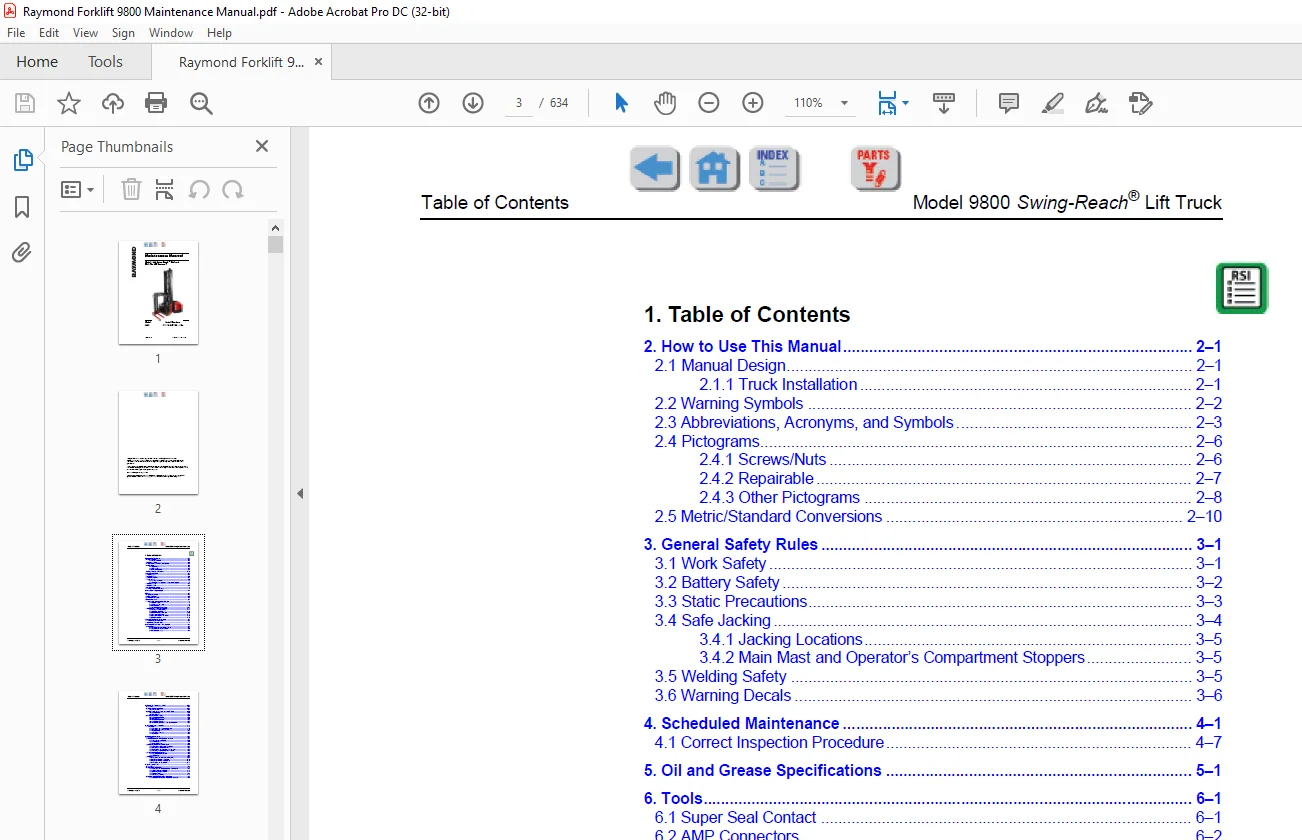
1 Table of Contents
2 How to Use This Manual 2–1
2 1 Manual Design 2–1
2 1 1 Truck Installation 2–1
2 2 Warning Symbols 2–2
2 3 Abbreviations, Acronyms, and Symbols 2–3
2 4 Pictograms 2–6
2 4 1 Screws/Nuts 2–6
2 4 2 Repairable 2–7
2 4 3 Other Pictograms 2–8
2 5 Metric/Standard Conversions 2–10
3 General Safety Rules 3–1
3 1 Work Safety 3–1
3 2 Battery Safety 3–2
3 3 Static Precautions 3–3
3 4 Safe Jacking 3–4
3 4 1 Jacking Locations 3–5
3 4 2 Main Mast and Operator’s Compartment Stoppers 3–5
3 5 Welding Safety 3–5
3 6 Warning Decals 3–6
4 Scheduled Maintenance 4–1
4 1 Correct Inspection Procedure 4–7
5 Oil and Grease Specifications 5–1
6 Tools 6–1
6 1 Super Seal Contact 6–1
6 2 AMP Connectors 6–2
6 3 Miscellaneous Tools 6–3
7 Frame pivot – 0320 7–1
7 1 Removal/Reassembly of Rear Chassis 7–1
7 1 1 Special Tools 7–1
7 1 2 Standard Hand Tools 7–1
7 1 3 Disassembly 7–2
7 1 4 Dismantle the Rear Chassis 7–11
7 2 Replacing the Bearing Frame Links 7–12
7 2 1 Remove the Old Bearings 7–12
7 2 2 Install New Bearings 7–13
7 2 3 Reinstall the Rear Chassis 7–16
7 2 4 Reassemble the Truck 7–17
7 2 5 Lower the Truck to the Ground 7–18
7 2 6 Final Assembly 7–18
8 General Tightening Torque – 0400 8–1
8 1 Galvanized, Non-Oiled Bolts 8–1
8 2 Untreated, Lubricated Bolts 8–1
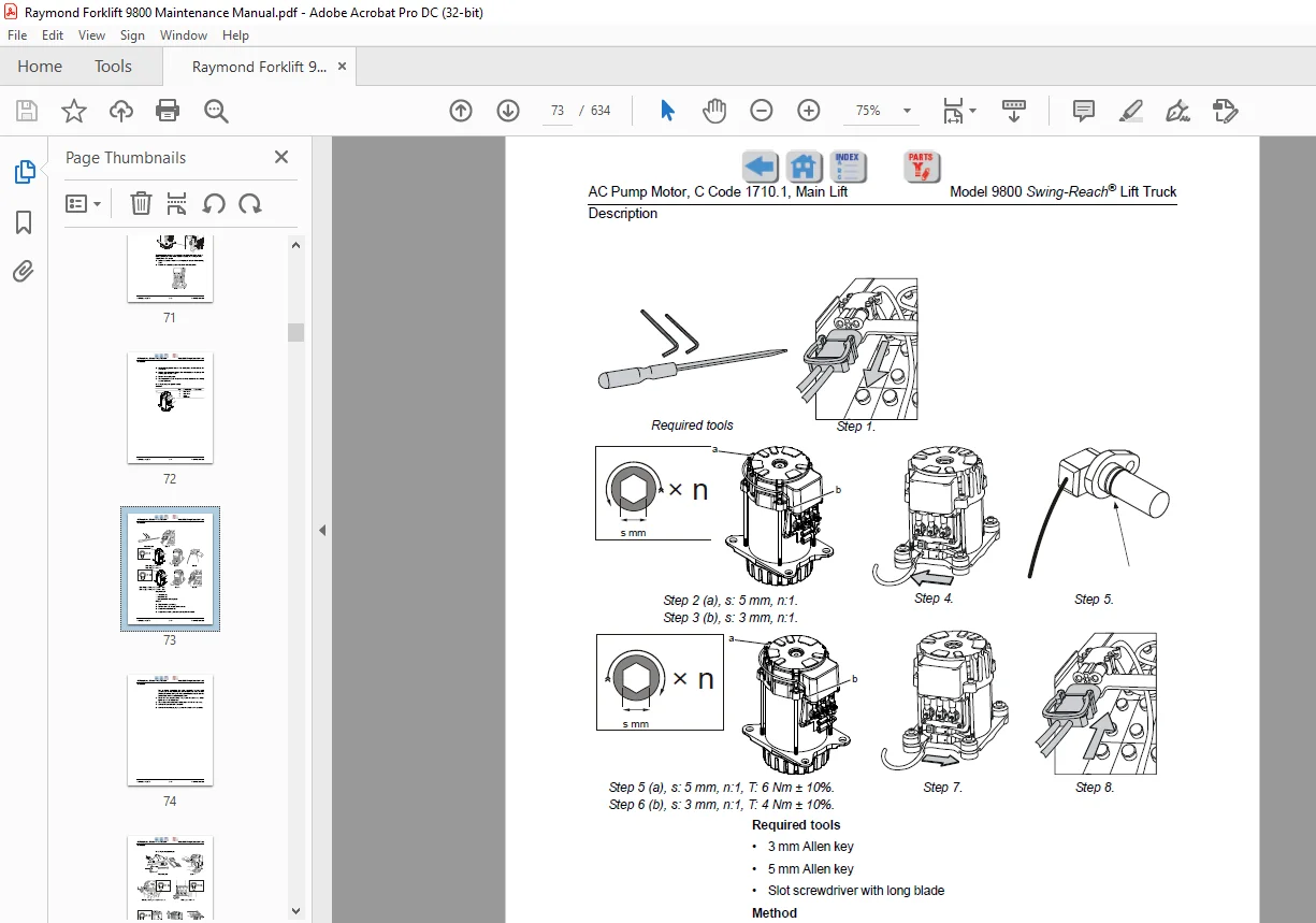
9 AC Pump Motor, C Code 1710 1, Main Lift 9–1
9 1 Description 9–1
9 1 1 Replacing the Temperature Sensor 9–3
9 1 2 Replacing the Speed Sensor 9–4
9 1 3 Replacing Bearings 9–7
Publication: 1203870 1 – 2 Issued: 20 Jan 2016
Table of Contents Model 9800 Swing-Reach® Lift Truck
10 Electric DC Pump Motor – 1710 2 10–1
10 1 General 10–1
10 2 Disassembled Pump Motor 10–1
10 2 1 Connection 10–1
10 3 Disassembly and Assembly of the Pump Motor 10–2
10 3 1 Disassembly 10–2
10 3 2 Installation 10–3
10 4 Replacing the Ball Bearing 10–4
10 4 1 Disassembly (D side) 10–4
10 4 2 Installation 10–4
10 4 3 Disassembly (N side) 10–5
10 4 4 Assembly (N side) 10–5
10 4 5 Carbon Brushes and Carbon Brush-Rocker 10–5
11 AC Drive Motor, C Code 1760 11–1
11 1 Description 11–1
11 1 1 Replacing the Temperature Sensor 11–2
11 1 2 Replacing the Speed Sensor 11–2
11 1 3 Disassembly 11–3
11 1 4 Replacing Bearings 11–6
11 1 5 Assembly 11–8
12 Drive Unit/Gear – 2550 12–1
12 1 General 12–1
12 2 Components/Data of the Drive Unit and Gear 12–1
12 2 1 Component Identification 12–2
12 2 2 Technical Data 12–4
12 2 3 Dismantled Gear 12–4
12 3 Replacing the Drive Motor/Drive Gear 12–4
12 3 1 Dismantling of Drive Unit from Truck 12–5
12 3 2 Installing the Drive Unit in Truck 12–5
12 3 3 Dismantling the Drive Motor and the Gear 12–6
12 3 4 Installing the Drive Motor and the Gear 12–6
12 4 Oil Level Check/Replacement 12–7
12 4 1 Checking/Refilling the Oil 12–7
12 4 2 Oil Change 12–7
12 5 Repairs 12–8
12 5 1 Replacing the Drive Axle Jointing Ring 12–9
12 5 2 Leakage from the Top Cover 12–10
12 5 3 Leakage from the Lower Cover 12–10
12 5 4 Replacing the Wheel Bolts 12–11
13 Brake System – 3100 13–1
13 1 General 13–1
13 2 Description of Functions 13–1
13 2 1 Releasing the Directional/Speed Control Knob 13–1
13 2 2 Travel Direction Selector 13–1
13 2 3 Pressing the Brake Button 13–1
13 2 4 Parking Brake 13–3
13 2 5 Emergency Braking 13–3
13 3 Electro-Mechanical Disc Brake, Drive Motor 13–3
13 3 1 Maintenance Schedule and Maintenance Work 13–4
Publication: 1203870 1 – 3 Issued: 20 Jan 2016
Table of Contents Model 9800 Swing-Reach® Lift Truck
13 4 Replacing Brake Unit and Dismantling Brake Unit to
Replace Friction Disc 13–5
13 4 1 Replacing the Brake Unit 13–5
13 4 2 Dismantling a Brake Unit/Checking/Replacing a Brake Disc 13–7
13 4 3 Check and Adjust the Brake Force 13–8
13 4 4 Clean 13–8
13 4 5 Checking the Air Gap 13–8
13 4 6 Checking and Adjusting the Brake Force 13–9
13 4 7 Troubleshooting 13–9
13 5 Disc Brake with Multiple Discs, Support Arms 13–10
13 5 1 Checking the Play/Wear 13–10
13 5 2 Dismantling 13–11
13 5 3 Inspection 13–12
13 5 4 Installation 13–12
13 5 5 Maintenance 13–12
13 5 6 Adjusting the Play 13–13
14 Wheels – 3500 14–1
14 1 Drive Wheels – 3530 14–1
14 1 1 General 14–1
14 1 2 Disassemble the Drive Wheel 14–1
14 1 3 Assembling the Drive Wheel 14–1
14 1 4 Available Wheel Qualities 14–2
14 2 Support Arm Wheels – 3550 14–2
14 2 1 Dismantling the Wheel 14–2
14 2 2 Assembling the Wheel 14–4
14 2 3 Dismantling/Assembling the Wheel Bearings 14–5
14 2 4 Support Arm Wheels, Shimming 14–6
14 2 5 Available Wheel Qualities 14–6
15 Steering System – 4000 15–1
15 1 General 15–1
15 1 1 Steering Components 15–3
15 1 2 Hydraulic Diagram, Steering System 15–4
15 2 Function Description 15–5
15 2 1 Electrical System 15–5
15 2 2 Replacing the Steering Angle Sensor 15–7
15 2 3 Hydraulic System 15–9
15 2 4 Temperature and Voltage Compensation 15–9
15 3 Troubleshooting 15–10
15 3 1 Operations/Repair, Hydraulics 15–10
16 Steering Cylinder – 4160 16–1
16 1 Instructions for Checking for Internal Leaks 16–1
16 1 1 Checks Made Together with 2000-Hours Service 16–1
16 1 2 When Wear is Suspected 16–1
16 2 Recommended Procedure 16–1
16 3 Remedial Actions 16–3
16 3 1 Procedure 16–3
16 4 Removing a Steering Cylinder from the Truck 16–4
16 5 Installing a Steering Cylinder on the Truck 16–6
16 6 Repairs to the Front Steering Cylinder Mount 16–7
16 6 1 Background 16–7
16 6 2 Repair Material 16–7
16 6 3 Measures 16–7
Publication: 1203870 1 – 4 Issued: 20 Jan 2016
Table of Contents Model 9800 Swing-Reach® Lift Truck
17 Wire Guidance System – 4500 17–1
17 1 Wire Guidance 17–1
17 1 1 General 17–1
17 2 Wire Guidance Components 17–3
17 2 1 Antennas, W1, W2 17–4
17 2 2 Travel Speeds 17–11
17 2 3 Description of the Function 17–13
17 3 “Best Practice” for Adjusting the Wire Guidance 17–20
17 3 1 Set-Up Procedure 17–20
17 4 Parameters 17–22
17 4 1 General Wire Guidance Parameters 17–22
17 4 2 Learned Calibration Values, Steering 17–22
17 4 3 Learned Calibration Data, Wire Guidance 17–22
17 5 Warning and Fault Codes 17–22
18 Electrical System – 5000 18–1
18 1 General 18–1
18 1 1 Terminology 18–3
18 1 2 Truck Firmware Applications 18–3
18 1 3 Communication 18–3
18 2 Main Computer Unit (MCU) (A5) 18–4
18 2 1 General 18–4
18 2 2 Voltage Feed 18–6
18 2 3 Battery Negative 18–6
18 2 4 Electric Connectors 18–6
18 2 5 Internal Status Monitoring 18–6
18 2 6 Resetting the Battery Indicator 18–7
18 2 7 External Inputs and Outputs 18–7
18 2 8 Installing a New Card in the Truck 18–10
18 2 9 Programming the MCU 18–10
18 3 Fork Control Unit (FCU) (A4) 18–11
18 3 1 General 18–11
18 3 2 Voltage Feed 18–12
18 3 3 Battery Negative 18–12
18 3 4 Electric Connectors 18–12
18 3 5 Safety Measure 18–12
18 3 6 External Inputs and Outputs 18–12
18 3 7 Installing a New Card in the Truck 18–13
18 3 8 Programming 18–13
18 4 Integrated Control Panel (ICP) (A16) 18–14
18 4 1 General 18–14
18 4 2 ICP Modules 18–16
18 4 3 Voltage Feed 18–17
18 4 4 Battery Negative 18–17
18 4 5 External Inputs and Outputs 18–18
18 4 6 Installing a New ICP in the Truck 18–20
18 4 7 Programming 18–20
18 5 Motor Controllers, ACTL (A1), ACTR (A31),
and ACH (A2) Generation 5 18–21
18 5 1 General 18–21
18 5 2 ACT Regulators, A1/A31 18–22
18 5 3 ACH Regulator, A2 18–24
18 5 4 Troubleshooting 18–26
18 5 5 Connection of Power Cables 18–38
Publication: 1203870 1 – 5 Issued: 20 Jan 2016
Table of Contents Model 9800 Swing-Reach® Lift Truck
18 5 6 Installing a New Frequency Converter in the Truck 18–38
18 5 7 Programming 18–38
18 5 8 Maintenance 18–39
18 5 9 Safety 18–39
18 5 10 Cleaning 18–39
18 6 DC Regulator, DCHI (A32) 18–39
18 6 1 General description 18–39
18 6 2 Connection Terminal and Terminal Pillars 18–41
18 6 3 Technical Data 18–41
18 6 4 Installing a New Transistor Panel 18–41
18 7 Parameters 18–42
18 8 Diagnostics and Troubleshooting 18–42
18 8 1 Maintenance 18–44
18 8 2 Safety 18–44
18 8 3 Cleaning 18–44
18 9 Hand-Held Terminal 1307 18–45
18 9 1 Using the Hand-Held Terminal 18–47
18 9 2 Viewing and Adjusting Parameters 18–48
18 9 3 SPECIAL PROGRAM MODE 18–49
18 9 4 Using the TEST Mode 18–49
18 9 5 Using the DIAGNOSTICS MODE 18–49
18 9 6 SPECIAL DIAGNOSTICS MODE 18–50
18 10 Electric System, Overview 18–51
18 11 Symbol List and Electrical Schematic 18–55
18 11 1 List of Symbols 18–55
18 12 Electrical Schematic 18–57
18 13 Component Location 18–92
18 13 1 Cabling Contacts 18–101
18 14 Functional Description, General 18–104
18 15 Functional Description, Starting, Driving, Steering and Braking 18–105
18 15 1 Battery Connected, Truck Switched OFF 18–105
18 15 2 Log-in/Start-up 18–105
18 15 3 Log-out/Switch-OFF 18–108
18 15 4 Presence Check 18–109
18 15 5 Selecting the Drive Direction/Driving 18–109
18 15 6 Service Mode 18–111
18 15 7 Travel Speeds 18–111
18 15 8 Steering 18–113
18 15 9 Braking 18–113
18 16 Electrical Description of the Hydraulic Functions 18–119
18 16 1 Allowed Combined Functions 18–119
18 16 2 Monitoring and Functional Limitations 18–120
18 16 3 Slack Chain Guard 18–121
18 16 4 Height Measurement 18–122
18 16 5 Operator’s Compartment Lifting 18–124
18 16 6 Special Height (Lift Limiter Function) 18–126
18 16 7 Operator’s Compartment Lowering 18–127
18 16 8 Operator’s Compartment Lift/Lower with
Forks Set Straight Ahead 18–129
18 17 Turret Head Unit 18–130
18 18 Miscellaneous Electrical Functions 18–141
18 19 Narrow Aisle ID System 18–142
Publication: 1203870 1 – 6 Issued: 20 Jan 2016
Table of Contents Model 9800 Swing-Reach® Lift Truck
18 20 Display 18–143
18 20 1 Normal Mode 18–143
18 20 2 Information Mode 18–145
19 Parameters – 5700 19–1
19 1 General 19–1
19 2 Accessing Parameters 19–2
19 2 1 Operator Parameters 19–2
19 3 Truck Parameters 19–4
19 3 1 MCU Parameters 19–6
19 3 2 MCU Parameters 19–31
19 3 3 FCU Parameters, Turret Head Fork Unit 19–32
19 3 4 ICP Parameters 19–40
20 Calibration – 5700 20–1
20 1 General 20–1
20 1 1 Accessing Calibration Mode 20–1
20 1 2 Menu Navigation 20–2
20 2 Calibration of the ICP Controls – “CONTROLS” 20–3
20 3 Calibration of Steering – “STEERING” 20–4
20 3 1 Calibration of the Articulated Center Potentiometer 20–4
20 3 2 Calibration of the Control Valves 20–5
20 4 Calibration of Wire Guidance – “WIRE” 20–6
20 4 1 “Learn Offset” 20–6
20 4 2 Learn Frequency 20–6
20 5 Calibration of Turret Head Fork Unit Functions – “FORKS” 20–7
20 5 1 Counterclockwise Rotation 20–7
20 5 2 Clockwise Rotation 20–7
20 5 3 Calibration of Traversing/Lifting, “TRAV/LIFT” 20–8
20 5 4 Fork Lowering – “LOWER” 20–9
20 6 Calibration of Weight Indication – “WEIGHT” 20–10
20 7 Calibration of B Cylinder Pressure – “PRESSURE” 20–11
20 8 Calibration of Height Indication 20–12
20 9 Learn Status Codes – FCU 20–14
21 Fault Codes – 5700 21–1
21 1 General 21–1
21 2 Warning and Fault Codes 21–1
21 2 1 System Response Logic 21–3
21 3 Fault Codes, Description 21–4
21 3 1 ICP, Code Group 1 21–4
21 3 2 MCU, Code Group 2 21–11
21 3 3 Drive System, Code Group 3 21–19
21 3 4 Operator’s Compartment Lift System, Code Group 4 21–27
21 3 5 Steering System, Code Group 5 21–33
21 3 6 Mini-Mast and Turret Head Fork Unit Systems,
Code Group 6 21–48
22 Hydraulic System – 6000 22–1
22 1 General 22–1
22 2 Hydraulic Cleanliness 22–1
22 2 1 Packaging 22–1
22 2 2 Handling 22–1
22 2 3 Storage 22–2
22 2 4 Work Procedures 22–2
22 2 5 Inspection Measures 22–2
Publication: 1203870 1 – 7 Issued: 20 Jan 2016
Table of Contents Model 9800 Swing-Reach® Lift Truck
22 3 Symbols 22–3
22 4 Hydraulic Schematics 22–5
22 5 Operator’s Compartment Lifting 22–12
22 5 1 General 22–12
22 5 2 Operator’s Compartment Lifting – S44 closed 22–12
22 5 3 Operator’s Compartment Lowering – S70 closed 22–12
22 5 4 AC Hydraulic Unit, Components 22–13
22 5 5 Hydraulic Flow Diagram, Operator’s Compartment Lifting 22–14
22 5 6 B Cylinder System 22–15
22 6 Mini-Mast And Steering 22–17
22 6 1 General 22–17
22 6 2 Hydraulic Flow Diagram – Mini-Mast and Steering 22–18
22 6 3 Fork Rotation 22–21
22 6 4 Traversing 22–21
22 6 5 Mini-Mast Lifting 22–22
22 6 6 Mini-Mast Lowering 22–22
22 6 7 Steering 22–22
22 7 Extra Hydraulic Function 22–23
22 7 1 Valves Used for the Extra Hydraulic Functions 22–23
22 7 2 Hydraulic Diagram, Extra Hydraulic Function 22–24
22 8 Operations/Repair 22–25
22 8 1 General 22–25
22 8 2 Filter 22–26
22 8 3 Hydraulic Connections 22–28
22 8 4 General Repair Instructions, Valves 22–34
23 Hydraulic Tank – 6110 23–1
23 1 Replace the Hydraulic Oil 23–1
23 1 1 Emptying the Tank 23–1
23 1 2 Filling the Tank 23–2
23 2 Tank Removal 23–2
23 3 Installing a New Tank 23–6
24 Hydraulic Pump – 6140 24–1
24 1 General 24–1
24 2 Bleeding the Hydraulic Pumps 24–3
24 2 1 Bleeding the Hydraulic Pump for Steering
and Fork Hydraulics (B) 24–3
24 2 2 Bleeding the Hydraulic Pump for Main Lift (A1, A2) 24–4
24 3 Replacing the Hydraulic Pump for Main Lift (A1, A2) 24–4
24 3 1 Disassembly 24–4
24 3 2 Installation 24–6
24 4 Replacing the Hydraulic Pump for Steering and Fork Hydraulics (B) 24–8
24 4 1 Disassembly 24–8
24 4 2 Installation 24–10
24 5 Troubleshooting Internal Leakage in the Hydraulic Pump
for Steering and Fork Hydraulics (B) 24–12
25 Accumulators – 6280 25–1
25 1 Charging of the Lifting and Steering Accumulators 25–1
25 1 1 Preparations 25–2
25 1 2 Measuring the Pressure in the Lifting Accumulator 25–3
25 1 3 Charging the Lifting Accumulator 25–6
25 2 Measuring the Pressure in the Steering Accumulator 25–7
25 2 1 Charging the Steering Accumulator 25–8
Publication: 1203870 1 – 8 Issued: 20 Jan 2016
Table of Contents Model 9800 Swing-Reach® Lift Truck
26 Main Lift Cylinder – 6610 26–1
26 1 Replacing the Seal in the B Cylinder 26–1
27 Main Mast and Mast Stoppers – 7100 27–1
27 1 Setting the Operator’s Compartment and Mast Stoppers 27–1
27 1 1 Operator’s Compartment Stoppers 27–1
27 1 2 Setting the Operator’s Compartment Stoppers 27–2
27 1 3 Mast Stoppers 27–5
28 Main Lift Chain System – 7120 28–1
28 1 Checking the Chain Setting 28–1
28 2 Checking the Chain 28–1
28 2 1 Noise 28–1
28 2 2 Surface Rust 28–1
28 2 3 Rusty Links 28–1
28 2 4 Stiff Links 28–1
28 2 5 Bolt Rotation 28–2
28 2 6 Loose Bolts 28–2
28 2 7 Outline Wear 28–2
28 2 8 Stretching 28–3
28 2 9 Damage 28–4
28 2 10 Damaged Discs 28–4
28 2 11 Damaged Bolts 28–4
28 2 12 Dirty Chain 28–4
28 3 Cleaning 28–4
28 4 Lubrication 28–5
28 5 Adjusting Chains 28–6
28 5 1 Tool List 28–6
28 5 2 Main Lift Chain Adjustment 28–6
28 5 3 Operator’s Compartment Chain Adjustment 28–8
28 5 4 Mini-Mast Chain Adjustment 28–8
29 Mini-Mast/Turret Head Fork Unit – 7200 29–1
29 1 General Description 29–1
29 2 Assembly/Disassembly of the Mini-Mast 29–2
29 2 1 Mast Assembly 29–2
29 2 2 Mast Disassembly 29–8
29 3 Inspection/Replacement of Belts Used for Fork Traversing 29–9
29 3 1 Check 29–9
29 3 2 Replacing the Belt 29–9
29 3 3 Checking Belt Tension 29–12
29 4 Friction Plate Adjustment 29–14
29 5 Parallel Adjustment of Forks 29–15
29 5 1 Measuring Fork Parallelism 29–15
29 5 2 Adjusting Fork Parallelism 29–16
30 End-of-Aisle Slowdown and Stopping – 8100 30–1
30 1 End-of-Aisle Slowdown 30–1
30 2 End-of-Aisle Stop 30–3
30 3 Parameters to check/adjust 30–4
Publication: 1203870 1 – 9 Issued: 20 Jan 2016
Table of Contents Model 9800 Swing-Reach® Lift Truck
31 Vertical Hold – 9390 31–1
31 1 General 31–1
31 2 Parameters 31–1
31 2 1 MCU Parameters 31–1
31 3 Programming 31–2
31 3 1 To Program the Fork Level (Option) 31–3
31 3 2 Using Vertical Hold 31–4
32 Preparation for Transport 32–1
32 1 General 32–1
32 2 Tool List 32–1
32 3 Dismantling the Truck 32–2
32 4 Laying Down the Truck 32–11
Appendix A: TruckCom A–1
A 1 Installation A–2
A 1 1 TruckCom A–2
A 1 2 Start TruckCom A–4
A 1 3 License Key Retrieval (required at first start-up only) A–4
A 1 4 Installing USB/CAN interface drivers A–6
A 1 4 1 CAN interfaces A–6
A 1 4 2 Updating software in the USB/CAN Interface A–7
A 2 Retrieving/Downloading Software A–8
A 2 1 PC users A–8
A 2 2 TruckCom Dialog Box A–9
A 3 Connecting to Truck A–10
A 4 Using TruckCom A–11
A 4 1 Navigating Drop-down Lists A–13
A 4 1 1 Node Drop-down List A–13
A 4 1 2 Action Drop-down List A–13
Index I–1
IMAGES PREVIEW OF THE MANUAL:
Questions? Email us: [email protected]
https://vimeo.com/836433245?share=copy
PLEASE NOTE:
- This is the SAME MANUAL used by the dealerships to diagnose your vehicle
- No waiting for couriers / posts as this is a PDF manual and you can download it within 2 minutes time once you make the payment.
- Your payment is all safe and the delivery of the manual is INSTANT – You will be taken to the DOWNLOAD PAGE.
- So have no hesitations whatsoever and write to us about any queries you may have : heydownloadss @gmail.com
S.M