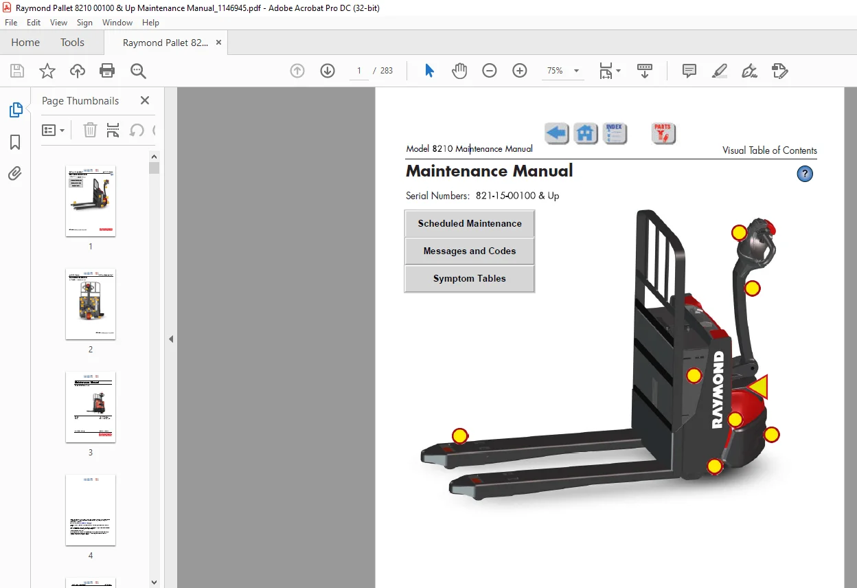
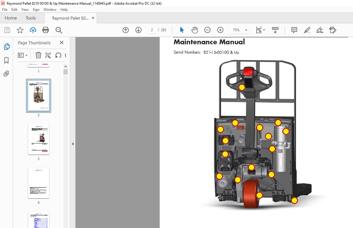
RAYMOND Pallet 8210 Maintenance Manual SN821-15-00100 & Up – PDF DOWNLOAD
Original price was: $89.00.$27.95Current price is: $27.95.
RAYMOND Pallet 8210 Maintenance Manual SN821-15-00100 & Up – PDF DOWNLOAD
Description
RAYMOND Pallet 8210 Maintenance Manual SN821-15-00100 & Up – PDF DOWNLOAD
FILE DETAILS:
RAYMOND Pallet 8210 Maintenance Manual SN821-15-00100 & Up – PDF DOWNLOAD
Language : English
Pages : 283
Downloadable : Yes
File Type : PDF
Size:29.9 MB
DESCRIPTION:
RAYMOND Pallet 8210 Maintenance Manual SN821-15-00100 & Up – PDF DOWNLOAD
Manual Design
- This manual is designed to give personnel with an expected level of expertise the technical information necessary to maintain, troubleshoot, and repair a Raymond product.
- The two-line header at the top of each page contains the name of the manual, the title of the current section, and the topic contained on the page.
This manual consists of the following sections:
- 1.How to Use This Manual explains the manual format and design as well as abbreviations and symbols used.
- 2.Safety explains warning and caution notes, gives general safety rules and (as applicable) specific safety rules for batteries, static electricity, jacking, towing, transport, and welding.
- 3.Systems Overview includes general lift truck specifications, modes of operation, and setup/configuration information.
- 4.Scheduled Maintenance identifies the recommended maintenance tasks and intervals necessary to keep the lift truck working most efficiently.
- 5.Troubleshooting provides information used to isolate a problem or failing component based on the lift truck’s symptoms.
- 6.Messages, Codes, and Tests gives (as applicable) operator messages, fault codes, and procedures for running diagnostic tests.
- 7.Component Procedures contains component locator photos and step-by-step procedures for the testing, removal, installation, and adjustment of individual truck components. Components are grouped by system. A detailed List of Component Procedures can be found at the beginning of the section.
- 8.Theory of Operation explains signal flow within the electrical and hydraulic systems for various conditions of lift truck operation. This section also contains a detailed connection point table (Pinout Matrix) designed to assist in testing and troubleshooting the truck.
- Appendix contains reference information such as torque values, lubricants, and standard/metric conversions.
- Index alphabetically lists subject matter with applicable page references.
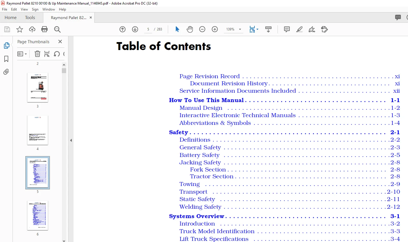
TABLE OF CONTENTS:
RAYMOND Pallet 8210 Maintenance Manual SN821-15-00100 & Up – PDF DOWNLOAD
Page Revision Record xi
Document Revision History xi
Service Information Documents Included xii
How To Use This Manual 1-1
Manual Design 1-2
Interactive Electronic Technical Manuals 1-3
Abbreviations & Symbols 1-4
Safety 2-1
Definitions 2-2
General Safety 2-3
Battery Safety 2-5
Jacking Safety 2-8
Fork Section 2-8
Tractor Section 2-8
Towing 2-9
Transport 2-10
Static Safety 2-11
Welding Safety 2-12
Systems Overview 3-1
Introduction 3-2
Truck Model Identification 3-3
Lift Truck Specifications 3-4
Operator Display and Programming 3-5
Special Truck Mode 3-5
Hour Meter (H) 3-5
Error Codes (E) 3-6
Error Code History 3-6
Changing Truck Parameters (P) 3-6
Programming Truck Parameters 3-6
Programming Service Parameters 3-8
Parameter Displays 3-8
Setting Individual PIN-key Codes 3-8
Display Part Numbers (Pn) 3-15
Display Test (d) 3-15
Service Display 3-16
Digital Inputs/Outputs from Traction Amplifier and VM 3-17
Traction Amplifier Inputs 3-17
Traction Amplifier Outputs 3-18
Digital Input from Vehicle Manager Control Sensors 3-18
Digital Input from Vehicle Manager Control Sensors 3-19
Typical Power Amplifier Status 3-19
Special Tools 3-20
Service Key 3-20
Programmable Maintenance Tool 3-20
Monitor Mode 3-21
Table of Contents Model 8210 Maintenance Manual
ii Publication:1146945, Revised: 12 Jan 2017
Faults Mode 3-21
Information Mode 3-22
Programmer Mode 3-22
FlashWare 3-24
Overview 3-24
Requirements 3-24
Installing FlashWare on PC 3-24
Connecting PC to Truck 3-24
Starting FlashWare 3-24
Scheduled Maintenance 4-1
Maintenance Guidelines 4-2
Initial 90 Day/250 Deadman Hours (HD) Maintenance 4-3
Every 180 Days or 500 Deadman Hours (HD) 4-4
Every 360 Days or 2000 Deadman Hours (HD) 4-6
Grease Fittings 4-7
Pin Locations 4-8
Troubleshooting 5-1
List of Troubleshooting Charts and Tables 5-2
Electrical Troubleshooting Guidelines 5-5
General 5-5
Shorts to Frame 5-5
Shorts to Frame Test 5-6
DC Electric Motors 5-8
DC Motor Types 5-8
Inspection 5-8
Service 5-9
Open Circuit Motor Test 5-12
Grounded Motor Test 5-12
Short-Circuited Armature 5-12
Short-Circuited Winding 5-13
AC Electric Motors 5-14
AC Motor Type 5-14
Open Winding 5-14
Shorted Winding 5-14
Hydraulic Troubleshooting Guidelines 5-15
Symptom Table: Electrical System 5-16
BDI Does Not Reset to 100% 5-16
Horn Does Not Sound When Horn Button Pushed
No Fault Codes 5-16
Green/Red LED on Keypad Not Illuminated When Key Pressed 5-17
Symptom Tables: Lift/Lower System 5-18
No Lift, Lift Motor Does Not Run, Travel is OK 5-18
No Lift or Slow Lift, Lift Motor Does Run 5-19
No Lower, Lift and Travel OK 5-19
Unable to Pick Up a Load 5-20
Slow Lower 5-20
Load Drifting/Settling 5-20
No Lift or Lower No Fault Codes 5-21
Model 8210 Maintenance Manual Table of Contents
Publication:1146945, Revised: 12 Jan 2017 iii
Symptom Tables: Travel (Forward/Reverse) System 5-22
Slow Travel, Lift/Lower OK No Fault Codes 5-22
Truck Does Not Accelerate Correctly 5-22
No Travel Mode No Fault Codes 5-23
No Travel or Slow Travel TA Flash Code 2,2, (Thermal Cutback)
Heatsink Temperature Exceeded 185°F (85°C)
Operator Display May Indicate Hot2 (C45) 5-23
No Travel, No Lift/Lower TA Flash Code 3,1
Operator Display May Indicate Error Code E106 5-23
No Travel, Main Contactor Does Not Close TA Flash Code 3,9
Operator Display Indicates Error Code E107 5-23
No Travel, No Lift/Lower TA Flash Code 1,3
Operator Display Indicates Error Code E202 5-24
No Travel, No Lift/Lower TA Flash Code 1,2
Operator Display Indicates Error Code E201 5-24
No Truck Functions Active TA Flash Code 1,7, (Low
Battery Voltage) Operator Display May Indicate E221 5-24
No Truck Functions Active TA Flash Code 1,8, (Excessive
Battery Voltage) Operator Display May Indicate E222 5-24
Charger Troubleshooting 5-25
Messages and Codes 6-1
List of Messages and Codes 6-2
Messages and Caution Codes 6-5
Code ‘GATE’ 6-5
Code ‘TEST’ 6-5
Code ‘SLO’ 6-5
Code ‘Sro’ (C14) 6-6
Code ‘LoGn’ (C15) (iWAREHOUSE® Only) 6-6
Code br_o (C16) 6-6
Code C19 6-7
Code HPd (C20) 6-7
Code C26 6-7
Code C27 6-8
Code C30 6-8
Code C31 6-8
Code C32 6-9
Code C33 6-9
Code C35 6-9
Code Lo (C41) 6-10
Code Hi (C42) 6-10
Code Cold (C43) 6-11
Code Hot1 (C44) 6-11
Code Hot2 (C45) 6-12
Code C46 (iWAREHOUSE® Only) 6-12
Code C47 (iWAREHOUSE® Only) 6-12
Code C48 6-13
Code C57 6-13
Code C60 6-13
Code C61 6-14
Code C62 6-14
Code C64 6-14
Code C66 6-15
Table of Contents Model 8210 Maintenance Manual
iv Publication:1146945, Revised: 12 Jan 2017
Code C67 6-15
Code C68 6-15
Code C70 6-16
Code C71 6-16
Code C72 6-16
Code 075 6-17
Code AC (C256) 6-17
Code C257 6-17
Code C258 6-17
Code C259 6-18
Code C380 6-18
Code C382 6-18
Code C383 6-19
Code C384 6-19
Code C385 6-19
Code C395 6-20
Code C405 6-20
Error Codes 6-21
Code E101 6-21
Code E106 6-21
Code E107 6-22
Code E108 6-22
Code E109 6-22
Code E140 6-23
Code E141 6-23
Code E142 6-23
Code E150 6-24
Code E151 6-24
Code E152 6-24
Code E157 6-25
Code E159 6-25
Code E160 6-25
Code E201 6-26
Code E202 6-26
Code E203 6-26
Code E220 6-27
Code E221 6-27
Code E222 6-27
Code E223 6-28
Code E224 6-28
Code E225 6-28
Code E228 6-29
Code E230 6-29
Code E232 6-29
Code E233 6-30
Code E235 6-30
Code E236 6-30
Code E248 6-31
Code E249 6-31
Code E250 6-31
Code E251 6-32
Code E254 6-32
Model 8210 Maintenance Manual Table of Contents
Publication:1146945, Revised: 12 Jan 2017 v
Code E690 6-32
Code E691 6-33
Code E700 6-33
Code E901 6-33
Code E996 6-34
Code E997 6-34
Code E998 6-34
Code E999 6-35
Code BTLR 6-35
Traction Amplifier Flash Codes 6-36
Delta-Q Charger Codes 6-38
Component Procedures 7-1
List of Component Procedures by Component System 7-2
Component Location Photos 7-5
Finish and Accessories 7-7
Tractor Covers 7-8
Tractor Cover Removal 7-8
Lower Cover Removal 7-8
Grille Cover Removal 7-9
Upper Cover Removal 7-9
Console Cover Removal 7-9
Tractor Cover Installation 7-10
Console Cover Installation 7-10
Upper Cover Installation 7-10
Grille Cover Installation 7-11
Lower Cover Installation 7-11
Tractor Bumper 7-13
Bumper Removal 7-13
Bumper Installation 7-13
Steering and Controls 7-15
Control Handle Head 7-16
Control Handle Disassembly 7-17
Horn Button/Switch Replacement 7-18
Lift/Lower Button Replacement 7-18
Push Button Replacement 7-18
Emergency Reverse Replacement 7-19
Keypad 7-20
Keypad Removal 7-20
Keypad Installation 7-21
Control Arm Assembly 7-23
Control Arm Removal 7-24
Control Arm Installation 7-24
Drive and Brake 7-27
Drive Unit Assembly 7-28
Drive Unit 7-30
Drive Unit Removal 7-30
Drive Unit Disassembly 7-31
Drive Unit Assembly 7-31
Drive Unit Installation 7-32
Table of Contents Model 8210 Maintenance Manual
vi Publication:1146945, Revised: 12 Jan 2017
Drive Unit Housing Lubrication 7-33
Gear Oil Level Check 7-33
Changing Gear Oil 7-33
Drive Wheel 7-34
Drive Wheel Removal 7-34
Tire Replacement 7-34
Drive Wheel Installation 7-35
Electromagnetic Brake Assembly 7-36
Brake Disc Location 7-36
Air Gap Inspection 7-36
Friction Disc Replacement 7-36
Electric Brake Release 7-37
Mechanical Brake Release 7-37
Electrical Components 7-39
Battery 7-40
Swing-out Battery Pack 7-40
Removal (entire battery pack) 7-40
Installation (entire battery pack) 7-41
Removal (single battery) 7-41
Installation (single battery) 7-41
Charger Replacement 7-42
Battery Maintenance 7-43
Battery Exterior Cleaning 7-43
To Charge a Battery 7-44
To Charge a Raymond Battery Pack (Option) 7-45
To Add Water to a Battery 7-45
Battery Specific Gravity 7-46
Specific Gravity Check 7-46
Battery Voltage Check 7-46
Battery Storage 7-46
Battery Connector 7-47
Inspection 7-47
Battery Connector Access and Removal 7-47
Cable Removal, Replacement, and Installation 7-48
Power Cables 7-49
Power Cable Repair 7-49
Wiring Harness 7-51
Wiring Harness Terminology 7-51
Wiring Harness Inspection 7-51
Wiring Harness Repair 7-52
Wiring Harness Soldering Procedures 7-52
Main Harness Bracket Removal 7-53
Main Harness Installation 7-53
Fuses 7-55
Fuse Test/Inspection 7-55
Horn 7-56
Horn Removal 7-56
Horn Installation 7-56
Model 8210 Maintenance Manual Table of Contents
Publication:1146945, Revised: 12 Jan 2017 vii
Traction Amplifier 7-57
To Clean the Traction Amplifier 7-57
Traction Amplifier Removal 7-57
Traction Amplifier Installation 7-57
Contactors 7-59
Resistance Testing 7-59
Contactor Removal 7-59
Contactor Installation 7-59
Lift Motor Solenoid 7-61
Switches (General) 7-62
Testing/Inspecting Switches 7-62
Main ON/OFF Switch 7-62
Main ON/OFF Switch Inspection 7-62
Main ON/OFF Switch Removal 7-62
Main ON/OFF Switch Installation 7-62
2-Position Keyed Switch (Optional) 7-63
Replacement 7-63
Arm Angle Proximity Switch 7-63
Replacement 7-63
Arm Angle Proximity Switch Adjustment 7-64
Lift Cutout Proximity Switch 7-65
Replacement 7-65
DC Motors, General 7-66
Motor Brush Inspection 7-66
Motor Brush Replacement 7-66
Motor Brush Spring Tension 7-67
Brush Spring Tension Inspection 7-67
Terminal Nuts 7-68
Polishing the Commutator 7-68
Traction Motor 7-69
Traction Motor Disassembly 7-71
Traction Motor Assembly 7-71
Speed Sensor (Encoder) Replacement 7-72
Terminal Block Replacement 7-73
Lift Motor 7-74
Lift Motor Removal 7-74
Lift Motor Installation 7-74
Lift Motor Brush Replacement 7-74
Hydraulic Components 7-75
Hydraulic Components 7-76
General Guidelines 7-76
Hydraulic Unit Torque Specifications 7-76
Hydraulic Fluid 7-77
Hydraulic Fluid Level Check 7-77
Changing Hydraulic Fluid 7-77
Hydraulic Unit 7-79
Hydraulic Unit Removal 7-80
Hydraulic Unit Installation 7-80
Hydraulic Reservoir 7-82
Reservoir Removal 7-82
Reservoir Installation 7-82
Table of Contents Model 8210 Maintenance Manual
viii Publication:1146945, Revised: 12 Jan 2017
Filter Screen and Inlet Tube 7-83
Filter Screen and Inlet Tube Removal 7-83
Filter Screen and Inlet Tube Installation 7-83
Hydraulic Pump 7-84
Hydraulic Pump Removal 7-84
Hydraulic Pump Installation 7-84
Hydraulic Pump Pressure Relief Valve Adjustment 7-85
Relief Valve Settings 7-85
Relief Valve Setting Check 7-85
Relief Valve Setting Adjustment 7-85
Hydraulic Cylinder 7-86
Cylinder Removal 7-86
Cylinder Disassembly 7-87
Cylinder Inspection 7-87
Cylinder Assembly 7-87
Cylinder Installation 7-88
Hydraulic Solenoid 7-89
Solenoid Removal 7-89
Solenoid Installation 7-89
Mast 7-91
Pallet Forks and Load Wheels 7-92
Load Wheels – Single 7-92
Removal and Replacement 7-92
Load Wheels – Dual 7-93
Removal and Replacement 7-93
Load Wheel Pull Rod 7-96
Removal and Replacement 7-97
Carrier Frame Linkage 7-97
Downstops 7-98
Lower Link Fork Heel Inspection 7-98
Downstop Adjustment 7-98
Skid Shoe Blocks 7-100
Skid Shoe Adjustment 7-100
Options 7-101
Cold Storage Conditioning 7-102
Cold Storage Hydraulic Fluid 7-102
Accessory Bar, Load Backrest Mounted 7-103
Accessory Bar 7-105
LED Work Light Installation 7-107
Operator Fan Installation 7-108
Casters 7-109
Caster Removal 7-109
Wheel Replacement 7-109
Caster Installation 7-109
Static Strap Replacement 7-110
Theory of Operation 8-1
Definitions 8-2
Acceleration 8-2
Arm Angle Proximity Switch 8-2
Click-to-Creep 8-2
Model 8210 Maintenance Manual Table of Contents
Publication: 1146945, Revised: 12 Jan 2017 ix
Continuity 8-2
Controller Area Network (CAN) 8-2
Creep Speed 8-2
Current Limiting 8-2
Deceleration (Neutral Braking) 8-3
Emergency Reverse 8-3
Fault Codes 8-3
High Pedal Disable (HPD) 8-3
Open Circuit 8-3
Overvoltage Cutoff 8-3
PIN-Key Code 8-3
Pulse Width Modulation 8-3
Regenerative Braking 8-3
Short Circuit or “Short” 8-4
Speed Limiting 8-4
Static Return to Off (SRO) 8-4
Thermal Cutback (Traction Amplifier) 8-4
Tractor 8-4
Truck Off Delay (Keypad only) 8-4
Undervoltage Cutoff 8-4
Vehicle Manager 8-4
Truck Starting 8-5
Traction System 8-6
Vehicle Manager 8-6
Traction Amplifier 8-6
Direction/Speed Control 8-6
Control Handle Positioning 8-6
Travel Request 8-6
Emergency Reverse 8-7
Electric Brake Release Switch 8-7
Lift/Lower System 8-8
Lift 8-8
Lower 8-8
Pinout Matrix 8-9
Appendix A-1
Lubrication Equivalency Chart A-2
Thread Adhesives, Sealants, and Lubricants A-3
Component Specific Service/Torque Chart A-4
Torque Chart – Standard (Ferrous) A-5
Torque Chart – Standard (Brass) A-6
Torque Chart – Metric (Ferrous) A-7
Torque Chart – Metric (Brass) A-8
Torque Chart – Thread Forming Screws A-9
Torque Chart – Hydraulic Fittings A-11
Torque Chart – Straight Thread Face Seal O-Rings A-12
Decimal Equivalent Chart A-13
Standard/Metric Conversions A-15
Index I-1
IMAGES PREVIEW OF THE MANUAL:
Questions? Email us: [email protected]
https://vimeo.com/834746506?share=copy
PLEASE NOTE:
- This is the same manual used by the DEALERSHIPS to SERVICE your vehicle.
- The manual can be all yours – Once payment is complete, you will be taken to the download page from where you can download the manual. All in 2-5 minutes time!!
- Need any other service / repair / parts manual, please feel free to contact us at heydownloadss @gmail.com . We may surprise you with a nice offer
S.M