Respironics BiPAP Focus Ventilator Service Manual PDF REF 1029568 Rev D
Original price was: $95.00.$29.95Current price is: $29.95.
Official Respironics California service manual for the BiPAP Focus Ventilator System. Covers complete theory of operation (pneumatic and electronic systems), diagnostic mode with significant event codes, OS software installation, system calibration, electrical safety testing, pressure accuracy verification, and 10 illustrated component removal/installation procedures. Includes full replacement parts list and ventilator specifications. REF 1029568 Rev D — 172 pages, instant PDF download.
Description
Respironics BiPAP Focus Ventilator Service Manual REF 1029568 Rev D PDF DOWNLOAD
DESCRIPTION:
Respironics BiPAP Focus Ventilator — Official Service Manual (REF 1029568 Rev D)
This is the complete official service manual for the Respironics BiPAP Focus Ventilator System, published by Respironics California, Inc. (REF 1029568, Revision D, 2006–2014). Produced using FrameMaker for Respironics / Philips Healthcare, this is the definitive technical reference for Respironics-authorized service engineers, hospital biomedical technicians (BMETs), and clinical engineering teams responsible for maintaining and repairing BiPAP Focus ventilators in acute, sub-acute, and intra-hospital transport settings.
This manual covers every discipline of BiPAP Focus servicing — from pneumatic and electronic theory of operation, through diagnostic mode operation, software installation, system calibration, performance verification, and complete board-level component replacement.
📋 File Details
| Detail | Information |
|---|---|
| Manual Name | BiPAP Focus Ventilator Service Manual |
| Reference Number | REF 1029568 Rev D |
| Models Covered | BiPAP Focus Ventilator System (CPAP & S/T modes) |
| Publisher | Respironics California, Inc. (Philips Healthcare) |
| Year | 2006–2014 (Revision D) |
| PDF Quality | Digitally produced, fully searchable, high resolution |
| Total Pages | 172 |
| File Format | PDF (US Letter, 612×792 pts) |
Table of Contents
Chapter 1 — Introduction and Intended Use
- Intended Use (noninvasive ventilation for adults >30 kg; acute, sub-acute, and intra-hospital transport)
- Ventilation Modes: CPAP and Spontaneous/Timed (S/T)
- Digital Auto-Trak leak compensation overview
- 1.1 Tools and Test Equipment (complete list with part numbers: DMM, electrical safety analyzer, flow source, pneumatic calibration analyzer, Respironics utility software, accessories)
- 1.2 Measurement Accuracy Requirements (pressure, flow, torque, voltage)
- 1.3 Where to Go for Help
Chapter 2 — Warnings and Cautions
- 2.1 Warnings (electric shock, battery fire risk, patient safety, diagnostic mode precautions, explosion hazard)
- 2.2 Cautions (ESD, filter maintenance, battery storage, cable handling, calibration printer requirement)
- 2.3 Notes
Chapter 3 — Theory of Operation
- 3.1 Pneumatic System (with full pneumatic diagram)
- 3.1.1 Air Inlet Filters (gray reusable particulate filter + white disposable ultra-fine filter)
- 3.1.2 Muffler (baffled noise reduction with recirculation path)
- 3.1.3 Blower (speed-controlled DC motor, single-stage impeller, closed-loop RPM control by controller PCB)
- 3.1.4 Flow Valve (electromagnetic coil, -125 to 675 mA range, closed-loop flow/pressure feedback)
- 3.1.5 Air Flow Sensor (closed-loop flow valve control, patient demand detection, leak rate calculation)
- 3.1.6 Diffuser (turbulence reduction at flow valve output)
- 3.2 Electronic System (dual microcontroller architecture — block diagram included)
- 3.2.1 User Interface PCB (Motorola 68332 MCU; VGA/keyboard/LED interface; USB + RS-232; power distribution: 18V/12V/5V/3.3V; primary alarm driver; remote alarm relay)
- 3.2.2 Controller PCB (blower speed control, flow valve control, pressure measurement, RS-232, backup alarm driver, flow sensor calibration, real-time clock, watchdog)
- 3.2.3 VGA Interface PCB (STN blue mode, quarter VGA 320×240, 0.36 mm dot pitch, integrated backlight inverter, RTC)
- 3.2.4 VGA Display (STN blue mode, quarter VGA 320×240)
- 3.2.5 External AC/DC Power Supply (90–240 VAC, 40–60 Hz, 120W, 18 VDC output)
- 3.2.6 Internal Battery (9.6V / 3.7 Ah NiMH; thermal fuse; thermistor; 45-min runtime at default settings; <5 hr charge time)
- 3.3 Back Panel (nurse call/serial port, USB port, AC/DC input, ON/OFF switch)
Chapter 4 — Periodic Maintenance
- 4.1 Preliminary Cleaning and Inspection (approved cleaning agents: mild detergent, 10% bleach, 91% isopropyl alcohol, quaternary ammonium germicide)
- 4.2 Cleaning the Reusable Air Inlet Filter (approved solutions: Palmolive/Dawn, vinegar, 99.9% isopropyl, 3% H₂O₂, Clorox bleach)
- 4.3 Replacing Air Inlet Filters
- 4.4 Battery Maintenance
- 4.4.1 Battery Operating Time (10–30 cmH2O pressure vs. runtime table: 60 min @ 10 cmH2O down to 20 min @ 30 cmH2O)
- 4.4.2 Battery Charging (NiMH auto-charge when AC connected and switch ON; <5 hr charge; storage depletion timeline)
- 4.4.3 Battery Replacement (step-by-step)
- 4.4.4 Fully Depleted Battery (2.80 VDC threshold; P/N 1040421 bootstrap charging cable procedure; time-sensitive reconnection steps)
- 4.5 Storing the Ventilator
Chapter 5 — Diagnostic Mode and Troubleshooting
- 5.1 Entering Diagnostic Mode (key sequence: Alarm/Reset + Alarm/Silence at power-up for 15 seconds)
- 5.2 Product Information (serial number, software version, hardware version display)
- 5.2.1 Date of Manufacture (12-digit serial number decode — YY/MM/DD from digits 5–10)
- 5.3 System Settings (language, operating time, since-service timer, date/time)
- 5.4 Preferences (display units — cmH2O/hPa/mbar; alarm volume 1–5; contrast 20–100%; brightness 10–100%; reverse video; screen lock)
- 5.5 Significant Event Log (200-event rolling log with date/time stamps)
- 5.6 Sensor Readings (real-time A/D counts and measured values for: +3.3V, +5V, +12V, +18Vin, +18V Boost, VBATT/VTEMP, VOptoCap, Board Temp, Ambient Temp, +18VINCMP, +18VBSTCMP, BattChrgFault, BattOnChrg, BattChrgToc, BattChrgRdy, PORLATCH, PWRSWMON, PWRSWLATCH)
- 5.7 Setting Up the Serial Interface for DRPT (HyperTerminal + Respironics cable P/N 1039800)
- 5.8 Generating a Diagnostic Report (DRPT) (step-by-step with sample output and field interpretation guide)
- 5.9 System Test Screen (alarms, indicators, blower, miscellaneous controls: VBattMeasEn, PWRSWCLK, PWRTUIOFF, PORLATCH, WDSTROBE)
- 5.10 Significant Event Codes (comprehensive table — codes 1 through 900+ with corrective actions, including: software errors, calibration failures, blower faults, flow/pressure sensor faults, battery/voltage failures, watchdog resets, POST results, alarm conditions, settings changes)
Chapter 6 — Ventilator Communications
- 6.1 Connecting the Service PC and Ventilator
- 6.2 Loading USB Drivers to the Service PC (step-by-step with screenshots)
- 6.3 Installing Operating Software on the Ventilator (firmware/OS installation via Respironics utility)
- 6.4 Reprogramming the BiPAP Focus Serial Number
Chapter 7 — Testing, Calibration, and Performance Verification
- 7.1 Test Equipment and Accessories (pneumatic analyzer, flow source, electrical safety analyzer)
- 7.2 Recommended Testing (post-repair test matrix)
- 7.3 Ventilator Run-in
- 7.4 Battery Test (monthly requirement; 45-min runtime at defaults)
- 7.5 Real-Time Clock Calibration
- 7.5.1 Downloading Real-Time Clock Calibration Software
- 7.5.2 Performing the Real-Time Clock Calibration
- 7.5.3 If Real-Time Clock Calibration Fails
- 7.6 System Calibration
- 7.6.1 Downloading System Calibration Software
- 7.6.2 Performing the System Calibration (full procedure using Respironics calibration utility)
- 7.7 Electrical Safety Test (Dale LT 5440 or equivalent)
- 7.8 Alarm/LED Test (primary alarm, backup alarm, remote relay, all LEDs)
- 7.9 Pressure Accuracy Test (±1% or ±0.20 cmH2O accuracy requirement)
- 7.10 Performance Verification Data Form
Chapter 8 — Component Removal/Installation (10 illustrated procedures)
- 8.1 Disconnecting Power
- 8.2 Top Cover
- 8.3 Display Assembly
- 8.4 User Interface PCB
- 8.5 Controller PCB
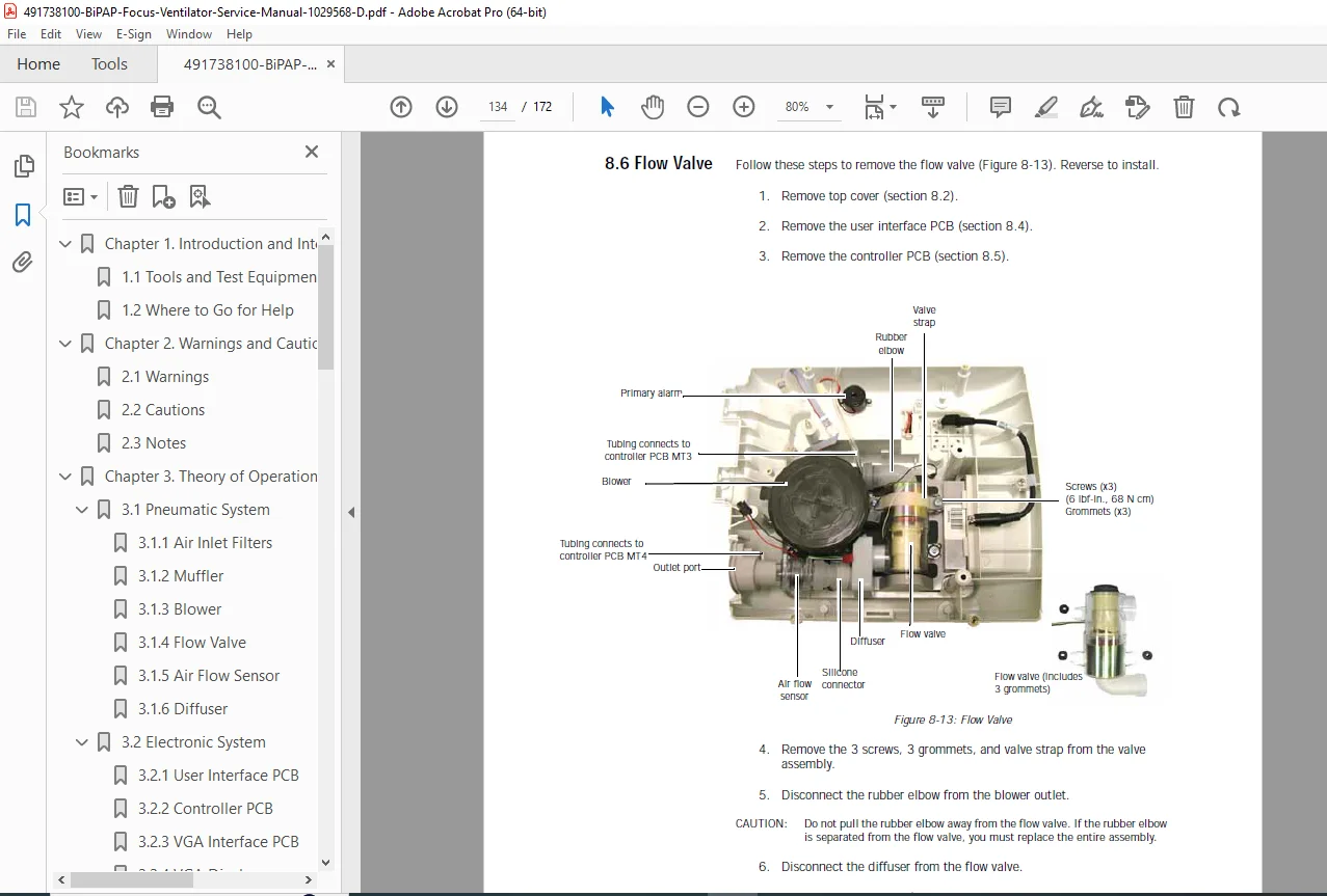
- 8.6 Flow Valve
- 8.7 Blower
- 8.8 Backup Alarm
- 8.9 Primary Alarm
- 8.10 Bottom Cover and Muffler
- 8.11 Interconnect Diagrams
Chapter 9 — BiPAP Focus Replacement Parts List
- 9.1 Complete Parts List
- 9.2 Exterior Parts (illustrated)
- 9.3 Front Panel / User Interface Parts (illustrated)
- 9.4 Ventilator Interior Parts (illustrated)
- 9.5 Communications Cables (P/N list)
- 9.6 Electronic Parts (PCBs, battery, power supply)
Chapter 10 — Specifications
- 10.1 Ventilator Specifications (full CPAP & S/T mode settings, measured data, alarm settings, options, nurse call connector pinout, power specs, physical specs)
- 10.2 Patient Circuit Details
- 10.3 Maximum Pressure Drop for Disconnect
- 10.4 Environmental Specifications
- 10.5 Date of Manufacture
- 10.6 Compliance (EN60601-1, EN 60601-1-2, EN ISO 10651-6:2004, WEEE)
- 10.7 Warranty
⚡ Key Technical Specifications at a Glance
| Specification | Value |
|---|---|
| Ventilation Modes | CPAP, Spontaneous/Timed (S/T) |
| IPAP Range | 4–30 cmH2O |
| EPAP Range | 4–25 cmH2O |
| Rate Range | 1–30 breaths/min |
| I-Time Range | 0.5–3.0 sec |
| Rise Time | 1–6 (0.1–0.6 sec) |
| Ramp Time | 0–45 min |
| Input Power | 100–240 VAC ±10%, 47–63 Hz, 3.0–1.5A |
| Power Supply Output | 120W, 18 VDC |
| Internal Battery | 9.6V / 3.7 Ah NiMH — 45 min runtime at defaults |
| Battery Charge Time | Typically under 5 hours |
| Display | Quarter VGA (320×240), STN blue mode, 0.36 mm dot pitch |
| Dimensions | 355 × 290 × 140 mm (H×W×D) |
| Weight | 4.5 kg (10 lbs.) |
| Operating Temp | +5°C to +35°C, 10–95% RH |
| Storage Temp | -20°C to +60°C, ≤95% RH |
| Atmospheric Pressure | 83–102 kPa (operating) |
| O2 Supplemental Flow | Maximum 15 L/min at ambient pressure |
| Standards | EN60601-1, EN 60601-1-2+A1:2000, EN ISO 10651-6:2004, IEC 601-1 Class I Type BF |
🔑 Why Biomedical Technicians Need This Manual
- ✅ Complete significant event code reference (100+ codes, codes 1–900+) — each with corrective actions in priority order covering all processor, calibration, pneumatic, battery, voltage, and alarm fault conditions
- ✅ Dual-microcontroller architecture explained — understand how User Interface PCB (Motorola 68332) and Controller PCB communicate and monitor each other for fail-safe operation
- ✅ Full system calibration procedure using Respironics RASP utility — essential after blower, flow valve, or controller PCB replacement
- ✅ Real-time clock calibration procedure with pass/fail guidance
- ✅ DRPT diagnostic report generation via HyperTerminal — capture and interpret the complete event log for root-cause analysis before replacing parts
- ✅ Firmware/OS re-installation — step-by-step USB driver loading and software flashing via Respironics utility
- ✅ Serial number reprogramming after PCB replacement
- ✅ Fully depleted battery recovery procedure using bootstrap charging cable P/N 1040421 — avoid unnecessary battery replacements
- ✅ Real-time sensor readings with A/D count ranges and conversion formulas for all voltage rails, battery, and temperature channels
- ✅ Complete parts list by assembly section with Respironics part numbers for ordering
- ✅ Nurse call station/serial connector pin-out for integration with hospital nurse call systems
A BiPAP Focus ventilator offline is a respiratory patient without non-invasive breathing support. Get the complete Respironics BiPAP Focus service and repair manual now — download instantly after purchase and restore your ventilator to full performance verification standards before the next patient needs it