Trusted Business
Verified & Licensed
Virus Free Files
100% Safe Downloads
Secure Payment
SSL Protected
Instant Delivery
Available Immediately
ROSCO Maximizer 3B Asphalt Distributor Operations, Service & Parts Manual 1005234-03 PDF DOWNLOAD
$35.95
ROSCO Maximizer 3B Asphalt Distributor Operations, Service & Parts Manual 1005234-03 PDF DOWNLOAD
ROSCO – A LeeBoy Company Maximizer 3B Asphalt Distributor
Instant PDF Download
Available immediately
Save to Your Device
Download & keep forever
Antivirus Scanned
100% virus-free
Trusted Worldwide
175,000+ customers
Description
ROSCO Maximizer 3B Asphalt Distributor Operations, Service & Parts Manual 1005234-03 PDF DOWNLOAD
FILE DETAILS:
ROSCO Maximizer 3B Asphalt Distributor Operations, Service & Parts Manual 1005234-03 PDF DOWNLOAD
Language : English
Pages : 364
Downloadable :Yes
File Type : PDF
IMAGES PREVIEW OF THE MANUAL:
Need help? Contact: [email protected]
https://vimeo.com/847940062?share=copy
DESCRIPTION:
INTRODUCTION:
ROSCO Maximizer 3B Asphalt Distributor Operations, Service & Parts Manual 1005234-03 PDF DOWNLOAD
- READ THIS MANUAL PRIOR TO OPERATING the unit. This manual is an important part of the machine and should be kept with the machine at all times in the dedicated storage container on the machine.
- Even though you may be familiar with similar equipment, you MUST read and understand this manual before operating this machine.
- Reading the manual will help you and others avoid injury and help prevent any damage to the machine.
- If this manual becomes lost or damaged, contact your authorized LeeBoy Dealer immediately to order a replacement (see Contact Information Section 3).
- This manual is intended as a guide for the safe and efficient use of the machine. This manual covers the procedures for proper operation and maintenance of the machine.
- This manual contains information that was available at the time of printing and is subject to change without notice.
- This manual should be used with all related supplemental books, engine and transmission manuals, and parts books. Related Service Bulletins should be reviewed to provide information regarding some of the recent changes.
- If any questions arise concerning this publication or others, contact your local LeeBoy Dealer for the latest available information.
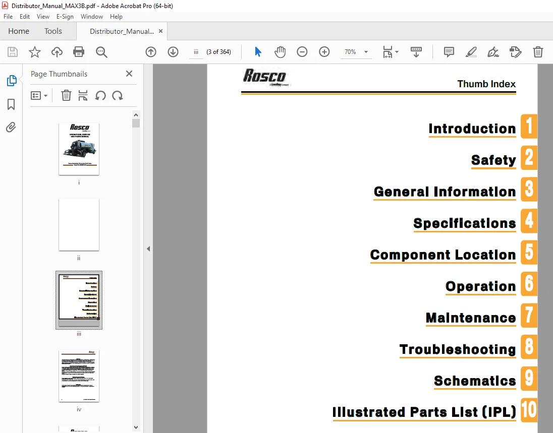
This manual provides information for use by the equipment operator under the following headings:
Safety—See Section 2 for important safety guidelines information.
General Information—See Section 3 for important warranty, contact, and nameplate information.
Specifications—See Section 4 for all major system specifications and typical torque value tables.
Component Location—See Section 5 for general overview of controls and major components.
Operation—See Section 6 for control functionality and normal equipment operation.
Maintenance—See Section 7 for basic preventive maintenance and repair procedures.
Troubleshooting—See Section 8 for problem descriptions and recommended solution tables.
Schematics—See Section 9 for schematic diagrams of electrical wiring
Illustrated Parts List (IPL)—See Section 10 for illustrations, descriptions and part numbers of available service parts.
TABLE OF CONTENTS:
ROSCO Maximizer 3B Asphalt Distributor Operations, Service & Parts Manual 1005234-03 PDF DOWNLOAD
ROSCO – A LeeBoy Company Maximizer 3B Asphalt Distributor
Table Of Contents................................................  5
Introduction..................................................... 11
Safety........................................................... 13
	Safety Precautions........................................... 14
	Safety Label Locations....................................... 18
General Information.............................................. 21
	Limited Warranty Policy...................................... 22
		Warranty................................................. 22
		Limitations.............................................. 22
		Items Not Covered........................................ 23
		Other Limitations........................................ 23
	Contact Information.......................................... 24
	Record of Ownership.......................................... 24
	Nameplate.................................................... 24
Specifications................................................... 25
	General Information.......................................... 26
		General.................................................. 26
		System Overview.......................................... 26
		Circulating System....................................... 26
		Burner System............................................ 27
		Plus One Controller...................................... 27
		In-Cab Operator System................................... 27
		Material Considerations.................................. 28
	Specification Tables......................................... 30
	Torque Specs................................................. 34
		Metric Fasteners......................................... 34
		Inch Fasteners........................................... 35
		Hydraulic Fittings....................................... 36
		Full Torque Nut Coupling Installation.................... 36
Component Location............................................... 41
	Outside Overview............................................. 42
	Main In-Cab Control Box...................................... 46
	Rear Controller.............................................. 50
	Run Screen................................................... 52
	LPG Burner System............................................ 54
Operation........................................................ 57
	Operator Safety Considerations............................... 59
		Regeneration............................................. 59
	Machine Break-In............................................. 60
		Before Starting.......................................... 60
		After 2 Hours Of Operation............................... 60
		After 8 & 20 Hours Of Operation.......................... 60
	Pre-Operating Check List..................................... 60
		Visual Inspection........................................ 60
		Service And Maintenance.................................. 60
		Spraybar Inspection...................................... 60
	Functional Check............................................. 61
		Hydraulic Circuit........................................ 61
		Hydrostatic Circuit...................................... 61
		Automatic Valve System................................... 62
	Asphalt Spraybar............................................. 63
		Preventing Spraybar Failure.............................. 64
	Valves And Nozzles........................................... 65
		Adjustment............................................... 65
		Nozzle Selection......................................... 66
	Burners & Torch Operation.................................... 66
		Diesel Burners........................................... 66
		Portable LPG Torch....................................... 71
	Plus One Controller.......................................... 72
		Distributor Operation.................................... 72
		In-Cab Controller Screens................................ 73
		Flow/Distance Calibration................................ 75
		Plus One Controller Error Messages....................... 76
		Electro Motive Radiation Interference.................... 76
	Modes Of Operation........................................... 77
		Load Mode................................................ 77
		Tank Circulate Mode...................................... 81
		Spray / Bar Circulate Mode (Bar Circulate)............... 83
		Spray /  Bar Circulate Mode (Spray)...................... 85
		Handspraying............................................. 87
		Handspray / Unload Mode.................................. 89
		Handspray Mode (Spray / Bar Circulate)................... 91
		Reverse Suction Mode..................................... 93
		Automated Clean-out Mode................................. 95
		Clean-out Mode........................................... 99
		Transfer Mode............................................101
		Unloading Mode...........................................103
	Washdown.....................................................104
	Combating Poor Visibility ...................................104
	Manual Operation.............................................105
		Calculations.............................................105
		Run Simulation Example...................................106
		Trial Run................................................107
Maintenance......................................................109
	General Information..........................................112
	Routine Maintenance..........................................112
		General Information......................................112
	Fluids And Lubricants........................................113
		Asphalt Pump Lubrication.................................113
		Grease For Other Components..............................113
		Hydraulic Oil............................................113
		Clean-out Solvent........................................113
		Truck Systems............................................114
	Tank Components..............................................114
		Tank Sump................................................114
		Top Opening..............................................114
		Capacity Indicator Gauge.................................115
		Mounting Hardware........................................115
	Asphalt Pump System..........................................116
		Asphalt Pump.............................................116
		Relief Valve.............................................116
		Discharge Screen.........................................117
		Load Line Screen.........................................118
		Pump Drive...............................................118
		Automatic Valves.........................................118
	Spraybar.....................................................120
	Hydraulic System.............................................121
	Burner System................................................122
		Diesel Burners...........................................122
		LPG Burners (Option).....................................122
	GPS Ground Speed Sensor......................................123
	Radar Horn (Option)..........................................123
	Daily Exterior Maintenance...................................124
	Storage......................................................124
	Hydraulic Fluids.............................................125
	Hydraulic Oil Requirements...................................125
	Safety Label Installation....................................126
Troubleshooting..................................................127
	General......................................................128
	Troubleshooting Charts.......................................128
Schematics.......................................................139
	Electrical Schematic - Plus One Overview ....................141
		Electrical Schematic - Plus One 1 of 5 ..................143
		Electrical Schematic - Plus One 2 of 5 ..................145
		Electrical Schematic - Plus One 3 of 5 ..................147
		Electrical Schematic - Plus One 4 of 5 ..................149
		Electrical Schematic - Plus One 5 of 5 ..................151
	Pneumatic Schematic - Control, Air 1 of 1 ...................153
	Electrical Schematic - Control, Front Machine 1 of 1 ........155
	Electrical Schematic - Control, Rear Machine 1 of 1 .........157
	Electrical Schematic - Control, LH Spraybar 1 of 1 ..........159
	Electrical Schematic - Control, RH Spraybar 1 of 1 ..........161
	Electrical Schematic - Can Bus Kit 1 of 4 ...................163
	Electrical Schematic - Can Bus Kit 2 of 4 ...................165
	Electrical Schematic - Can Bus Kit 3 of 4 ...................167
	Electrical Schematic - Can Bus Kit 4 of 4 ...................169
Illustrated Parts List (IPL).....................................171
	Platform Installation, w/o Handrail .........................174
		Rear Platform and Piping Assembly .......................176
		Asphalt Pump ............................................180
		Asphalt Pump Relief Valve ...............................182
		Transfer Line, Ground Level .............................184
		Automatic Valve, Cab Control ............................186
		Tank Valve Assembly .....................................188
		Flex Hose Assembly ......................................190
		Handspray  Wand Assembly ................................192
		Hydraulic, Front Live ...................................196
		Hydraulic, PTO ..........................................204
		Hydraulic Reservoir .....................................210
		Drive Shaft Group .......................................212
		Control Box, Plus One, 16 Ft Spraybar ...................214
		Ground Speed Sensor .....................................216
		Spraybar Assembly, 16 Foot ..............................218
		Potentiometer ...........................................224
		Spray Valve Assembly ....................................226
		Air Reservoir Group .....................................228
		Valve Box, Subassembly ..................................230
		Solenoid Valve, 8 Valve .................................232
		Diesel Burner, Double Flue, No Outfire I ................234
		Diesel Burner, Double Flue, No Outfire II ...............236
		Control Box, Diesel Burner ..............................238
		Burner Covers & Flue Liners .............................240
		Light & Reflector Group .................................242
		Decal Group .............................................244
		Ladder & Platform Group .................................246
		Tank Top Opening ........................................248
		Fender Group, Single Axle ...............................250
		Mud Flap Installation ...................................252
		Sampling Valve, Front Head ..............................254
		Overflow Attachment Group ...............................256
		Thermometers.............................................258
		Enviroflush System.......................................260
		Insulated Tank & Tank Components.........................262
		Spraybar Assembly, 18 FT.................................266
		Potentiometer............................................272
		Spray Valve Assembly.....................................274
		Spray Valve Assembly, 20 FT..............................276
		Spray Valve Assembly.....................................280
		Solenoid Valve, 10/12 Valve (For 18 FT Spraybar).........282
		Solenoid Valve, 12 Valve (For 20 FT Spraybar)............284
		Diesel Burner, Double Flue, Outfire, No Thermostat I.....286
		Diesel Burner, Double Flue, Outfire, No Thermostat II....288
		LPG Burners, Double Flue, Auto Ignition..................290
		LPG Burners, Double Flue, Manual Ignition................294
		LPG Tank, 52 Gallon......................................296
		Portable Torch Holder Assembly, LPG......................298
		Fender Group, Tandem Axle................................300
		Fender Group, Triple Axle................................302
		Mud Flap Group, Full Width...............................304
		Washdown System..........................................306
		Return Line Valve........................................310
		Tank & Ladder Group, 1000 Gallon Tank....................312
		Tank & Ladder Group, 1500 Gallon Tank....................314
		Tank & Ladder Group, 3000 Gallon Tank....................316
		Tank & Ladder Group, 3500 Gallon Tank....................318
		Tank & Ladder Group, 4000 Gallon Tank....................320
	Alphabetical Parts Index.....................................322
Safety........................................................... 13
	Safety Precautions........................................... 14
	Safety Label Locations....................................... 18
General Information.............................................. 21
	Limited Warranty Policy...................................... 22
		Warranty................................................. 22
		Limitations.............................................. 22
		Items Not Covered........................................ 23
		Other Limitations........................................ 23
	Contact Information.......................................... 24
	Record of Ownership.......................................... 24
	Nameplate.................................................... 24
Specifications................................................... 25
	General Information.......................................... 26
		General.................................................. 26
		System Overview.......................................... 26
		Circulating System....................................... 26
		Burner System............................................ 27
		Plus One Controller...................................... 27
		In-Cab Operator System................................... 27
		Material Considerations.................................. 28
	Specification Tables......................................... 30
	Torque Specs................................................. 34
		Metric Fasteners......................................... 34
		Inch Fasteners........................................... 35
		Hydraulic Fittings....................................... 36
		Full Torque Nut Coupling Installation.................... 36
Component Location............................................... 41
	Outside Overview............................................. 42
	Main In-Cab Control Box...................................... 46
	Rear Controller.............................................. 50
	Run Screen................................................... 52
	LPG Burner System............................................ 54
Operation........................................................ 57
	Operator Safety Considerations............................... 59
		Regeneration............................................. 59
	Machine Break-In............................................. 60
		Before Starting.......................................... 60
		After 2 Hours Of Operation............................... 60
		After 8 & 20 Hours Of Operation.......................... 60
	Pre-Operating Check List..................................... 60
		Visual Inspection........................................ 60
		Service And Maintenance.................................. 60
		Spraybar Inspection...................................... 60
	Functional Check............................................. 61
		Hydraulic Circuit........................................ 61
		Hydrostatic Circuit...................................... 61
		Automatic Valve System................................... 62
	Asphalt Spraybar............................................. 63
		Preventing Spraybar Failure.............................. 64
	Valves And Nozzles........................................... 65
		Adjustment............................................... 65
		Nozzle Selection......................................... 66
	Burners & Torch Operation.................................... 66
		Diesel Burners........................................... 66
		Portable LPG Torch....................................... 71
	Plus One Controller.......................................... 72
		Distributor Operation.................................... 72
		In-Cab Controller Screens................................ 73
		Flow/Distance Calibration................................ 75
		Plus One Controller Error Messages....................... 76
		Electro Motive Radiation Interference.................... 76
	Modes Of Operation........................................... 77
		Load Mode................................................ 77
		Tank Circulate Mode...................................... 81
		Spray / Bar Circulate Mode (Bar Circulate)............... 83
		Spray /  Bar Circulate Mode (Spray)...................... 85
		Handspraying............................................. 87
		Handspray / Unload Mode.................................. 89
		Handspray Mode (Spray / Bar Circulate)................... 91
		Reverse Suction Mode..................................... 93
		Automated Clean-out Mode................................. 95
		Clean-out Mode........................................... 99
		Transfer Mode............................................101
		Unloading Mode...........................................103
	Washdown.....................................................104
	Combating Poor Visibility ...................................104
	Manual Operation.............................................105
		Calculations.............................................105
		Run Simulation Example...................................106
		Trial Run................................................107
Maintenance......................................................109
	General Information..........................................112
	Routine Maintenance..........................................112
		General Information......................................112
	Fluids And Lubricants........................................113
		Asphalt Pump Lubrication.................................113
		Grease For Other Components..............................113
		Hydraulic Oil............................................113
		Clean-out Solvent........................................113
		Truck Systems............................................114
	Tank Components..............................................114
		Tank Sump................................................114
		Top Opening..............................................114
		Capacity Indicator Gauge.................................115
		Mounting Hardware........................................115
	Asphalt Pump System..........................................116
		Asphalt Pump.............................................116
		Relief Valve.............................................116
		Discharge Screen.........................................117
		Load Line Screen.........................................118
		Pump Drive...............................................118
		Automatic Valves.........................................118
	Spraybar.....................................................120
	Hydraulic System.............................................121
	Burner System................................................122
		Diesel Burners...........................................122
		LPG Burners (Option).....................................122
	GPS Ground Speed Sensor......................................123
	Radar Horn (Option)..........................................123
	Daily Exterior Maintenance...................................124
	Storage......................................................124
	Hydraulic Fluids.............................................125
	Hydraulic Oil Requirements...................................125
	Safety Label Installation....................................126
Troubleshooting..................................................127
	General......................................................128
	Troubleshooting Charts.......................................128
Schematics.......................................................139
	Electrical Schematic - Plus One Overview ....................  1
		Electrical Schematic - Plus One 1 of 5 ..................  1
		Electrical Schematic - Plus One 2 of 5 ..................  1
		Electrical Schematic - Plus One 3 of 5 ..................  1
		Electrical Schematic - Plus One 4 of 5 ..................  1
		Electrical Schematic - Plus One 5 of 5 ..................  1
	Pneumatic Schematic - Control, Air 1 of 1 ...................  1
	Electrical Schematic - Control, Front Machine 1 of 1 ........  1
	Electrical Schematic - Control, Rear Machine 1 of 1 .........  1
	Electrical Schematic - Control, LH Spraybar 1 of 1 ..........  1
	Electrical Schematic - Control, RH Spraybar 1 of 1 ..........  1
	Electrical Schematic - Can Bus Kit 1 of 4 ...................  1
	Electrical Schematic - Can Bus Kit 2 of 4 ...................  1
	Electrical Schematic - Can Bus Kit 3 of 4 ...................  1
	Electrical Schematic - Can Bus Kit 4 of 4 ...................  1
Illustrated Parts List (IPL).....................................171
	Platform Installation, w/o Handrail .........................174
		Rear Platform and Piping Assembly .......................176
		Asphalt Pump ............................................180
		Asphalt Pump Relief Valve ...............................182
		Transfer Line, Ground Level .............................184
		Automatic Valve, Cab Control ............................186
		Tank Valve Assembly .....................................188
		Flex Hose Assembly ......................................190
		Handspray  Wand Assembly ................................192
		Hydraulic, Front Live ...................................196
		Hydraulic, PTO ..........................................204
		Hydraulic Reservoir .....................................210
		Drive Shaft Group .......................................212
		Control Box, Plus One, 16 Ft Spraybar ...................214
		Ground Speed Sensor .....................................216
		Spraybar Assembly, 16 Foot ..............................218
		Potentiometer ...........................................224
		Spray Valve Assembly ....................................226
		Air Reservoir Group .....................................228
		Valve Box, Subassembly ..................................230
		Solenoid Valve, 8 Valve .................................232
		Diesel Burner, Double Flue, No Outfire I ................234
		Diesel Burner, Double Flue, No Outfire II ...............236
		Control Box, Diesel Burner ..............................238
		Burner Covers & Flue Liners .............................240
		Light & Reflector Group .................................242
		Decal Group .............................................244
		Ladder & Platform Group .................................246
		Tank Top Opening ........................................248
		Fender Group, Single Axle ...............................250
		Mud Flap Installation ...................................252
		Sampling Valve, Front Head ..............................254
		Overflow Attachment Group ...............................256
		Thermometers.............................................258
		Enviroflush System.......................................260
		Insulated Tank & Tank Components.........................262
		Spraybar Assembly, 18 FT.................................266
		Potentiometer............................................272
		Spray Valve Assembly.....................................274
		Spray Valve Assembly, 20 FT..............................276
		Spray Valve Assembly.....................................280
		Solenoid Valve, 10/12 Valve (For 18 FT Spraybar).........282
		Solenoid Valve, 12 Valve (For 20 FT Spraybar)............284
		Diesel Burner, Double Flue, Outfire, No Thermostat I.....286
		Diesel Burner, Double Flue, Outfire, No Thermostat II....288
		LPG Burners, Double Flue, Auto Ignition..................290
		LPG Burners, Double Flue, Manual Ignition................294
		LPG Tank, 52 Gallon......................................296
		Portable Torch Holder Assembly, LPG......................298
		Fender Group, Tandem Axle................................300
		Fender Group, Triple Axle................................302
		Mud Flap Group, Full Width...............................304
		Washdown System..........................................306
		Return Line Valve........................................310
		Tank & Ladder Group, 1000 Gallon Tank....................312
		Tank & Ladder Group, 1500 Gallon Tank....................314
		Tank & Ladder Group, 3000 Gallon Tank....................316
		Tank & Ladder Group, 3500 Gallon Tank....................318
		Tank & Ladder Group, 4000 Gallon Tank....................320
	Alphabetical Parts Index.....................................322
PLEASE NOTE:
- This is the same manual used by the dealers to diagnose and troubleshoot your vehicle
- You will be directed to the download page as soon as the purchase is completed. The whole payment and downloading process will take anywhere between 2-5 minutes
- Need any other service / repair / parts manual, please feel free to contact [email protected] . We still have 50,000 manuals unlisted
G.P