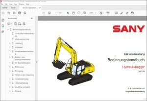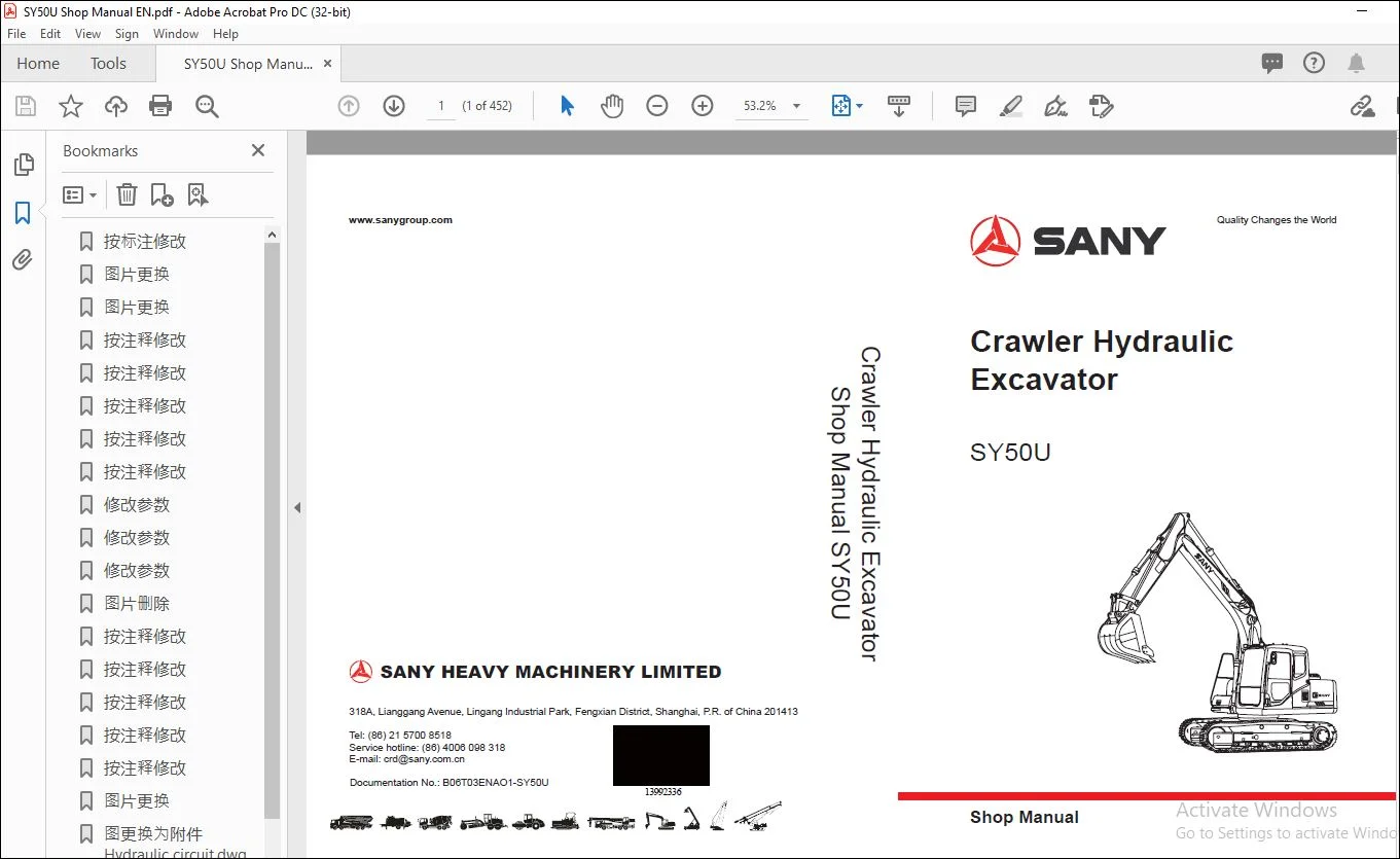
Sany SY50U Crawler Hydraulic Excavator Shop Manual – PDF DOWNLOAD
Original price was: $89.00.$28.95Current price is: $28.95.
Sany SY50U Crawler Hydraulic Excavator Shop Manual – PDF DOWNLOAD
Description
Sany SY50U Crawler Hydraulic Excavator Shop Manual – PDF DOWNLOAD
IMAGES PREVIEW OF THE MANUAL:
DESCRIPTION:
Sany SY50U Crawler Hydraulic Excavator Shop Manual – PDF DOWNLOAD
1 INTRODUCTION
1.1 How to Read the Manual
● Some attachments and optional parts presented in this shop manual may not be delivered to
certain areas. Consult your Sany distributor if any of them is required.
● Materials and specif cations are subject to change without notice.
1.1.1 Shop manual organization
This shop manual contains the necessary technical information for services performed in a workshop.
For ease of understanding, the manual is divided into the following sections.
Introduction
This section provides an overview of what is covered in the rest of this manual and how to use
this manual,.
Shop Safety
This section covers basic shop safety information relating to this equipment. It also describes
what the hazard alerts mean that are used throughout the manual.
Specif cations
Technical specif cation of work equipment and optional parts are given in this section.
Structure and functions
This section explains the structure and function of each component. It helps the reader to get a
better understanding of the machine structure, and also serves as a reference for troubleshooting.
Standard Values
This section explains the standard values for a new machine and judgement criteria for testing,
adjusting, and troubleshooting. This standard value table is used to check the standard values in
testing and adjusting and to judge parts in troubleshooting.
Testing and adjusting
This section details the inspection before and after repair work as well as the adjustment during
inspection and repair work. Troubleshooting table that involves “Fault”and “Cause”are also
included in this section.
Troubleshooting
This section explains the way to detect faulty parts and the method to repair them. This section is
divided into the following parts: Electrical system, Engine, Hydraulic and mechanical system and
Monitoring system.
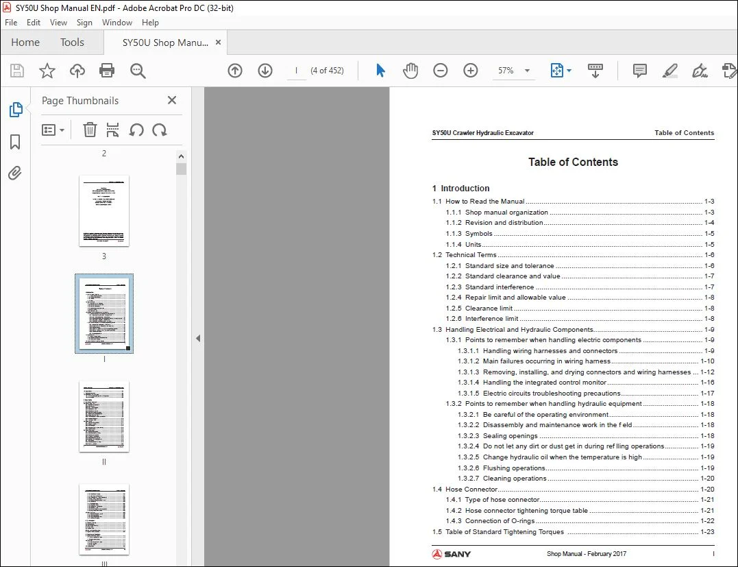
TABLE OF CONTENTS:
Sany SY50U Crawler Hydraulic Excavator Shop Manual – PDF DOWNLOAD
Introduction
11 How to Read the Manual 1-3
111 Shop manual organization 1-3
112 Revision and distribution 1-4
113 Symbols 1-5
114 Units 1-5
12 Technical Terms 1-6
121 Standard size and tolerance 1-6
122 Standard clearance and value 1-7
123 Standard interference 1-7
124 Repair limit and allowable value 1-8
125 Clearance limit 1-8
126 Interference limit 1-8
13 Handling Electrical and Hydraulic Components 1-9
131 Points to remember when handling electric components 1-9
1311 Handling wiring harnesses and connectors 1-9
1312 Main failures occurring in wiring harness 1-10
1313 Removing, installing, and drying connectors and wiring harnesses 1-12
1314 Handling the integrated control monitor 1-16
1315 Electric circuits troubleshooting precautions 1-17
132 Points to remember when handling hydraulic equipment 1-18
1321 Be careful of the operating environment 1-18
1322 Disassembly and maintenance work in the f eld 1-18
1323 Sealing openings 1-18
1324 Do not let any dirt or dust get in during ref lling operations 1-19
1325 Change hydraulic oil when the temperature is high 1-19
1326 Flushing operations 1-19
1327 Cleaning operations 1-20
14 Hose Connector 1-20
141 Type of hose connector 1-21
142 Hose connector tightening torque table 1-21
143 Connection of O-rings 1-22
15 Table of Standard Tightening Torques 1-23
Table of Contents SY50U Crawler Hydraulic Excavator
II Shop Manual – February 2017
16 Type of Bolts 1-24
17 Tightening Sequence 1-24
18 Maintenance of Half Flanges 1-25
181 Table of tightening torques for half f ange bolts 1-25
182 Temperature 1-31
2 Shop Safety
21 Hazard Alert Information 2-3
22 General Shop Safety 2-5
221 Rules and shop behavior 2-6
222 Housekeeping 2-6
223 Shop Liquids Storage 2-7
224 Cleaning the Parts 2-7
225 Cleaning the Machine 2-8
226 Appropriate Working Apparel 2-8
227 Personal Protective Equipment 2-8
228 Using the Correct Tools 2-9
229 Fire Extinguisher and Emergency Exits 2-9
2210 Electrical Dangers 2-10
2211 Hoisting a Load 2-10
23 Before Repair2-11
231 Safe Work Preparations 2-11
232 Preparing yourself 2-12
233 Lockout/Tagout 2-13
234 Two people when engine running 2-15
235 Safety Partners 2-15
24 Repair Precautions 2-16
241 Running the Machine 2-16
242 Mounting and Dismounting 2-17
243 Removing Attachments 2-18
244 Jacking Up the Machine 2-18
245 Adding Fluids to a System 2-18
246 Aligning Parts or Components 2-19
247 Driving Pins 2-19
248 When compressed air is used 2-19
249 Welding operation 2-20
SY50U Crawler Hydraulic Excavator Table of Contents
Shop Manual – February 2017 III
2410 Track Recoil Springs 2-20
2411 High-Pressure Fluid Lines 2-21
2412 Air-conditioning system maintenance 2-22
2413 High voltage precautions 2-22
2414 Disconnecting the System Power 2-23
2415 Accumulator 2-23
2417 Battery Hazards 2-24
2418 Jump-Start Safety 2-25
2419 Avoiding f re and explosion 2-26
2420 Chemical hazard 2-27
2421 Material Safety Data Sheets (MSDS) 2-27
2422 Proper disposal of wastes 2-28
25 Other Precautions 2-29
251 Sling work and giving signals 2-29
252 Using mobile crane 2-31
253 Using overhead hoist crane 2-31
254 Selecting wire ropes 2-33
3 Specif cations
31 Dimension Drawing 3-3
32 Working Ranges 3-4
33 Technical Specif cations 3-5
34 Weight Table 3-7
35 Capacity Table 3-8
36 Fuel and Coolant Capacities 3-9
37 Engine Performance Curve 3-10
4 Structure and Functions
41 Engine and Cooling System 4-3
411 Water cooler and oil cooler 4-3
412 Engine control device 4-5
42 Power Train 4-7
421 Power transmission system 4-7
422 Swing bearing 4-8
423 Swing motor 4-9
43 Undercarriage 4-10
Table of Contents SY50U Crawler Hydraulic Excavator
IV Shop Manual – February 2017
431 Track frame 4-10
432 Tensioning device 4-11
433 Tensioning device 4-12
44 Hydraulic System 4-13
441 Hydraulic lines 4-13
442 Hydraulic tank 4-14
443 Hydraulic pump 4-15
444 Control valve 4-17
445 Swing motor 4-22
446 Safety valve 4-26
447 Central swivel joint 4-28
448 Travel motor 4-29
4481 Working process of parking brake 4-32
4482 Working process of brake valve 4-33
449 Control system 4-35
4410 Pilot valve 4-36
4411 Travel pilot valve 4-42
4412 Oil source control valve 4-46
4413 Backup pilot valve 4-47
4414 Hydraulic cylinders 4-51
45 Air Conditioner System 4-52
451 Electric circuit 4-52
452 Component locations 4-53
453 Checking condenser f ns 4-55
454 Refrigerant-f lling operation 4-56
455 Troubleshooting with a manifold pressure gauge 4-57
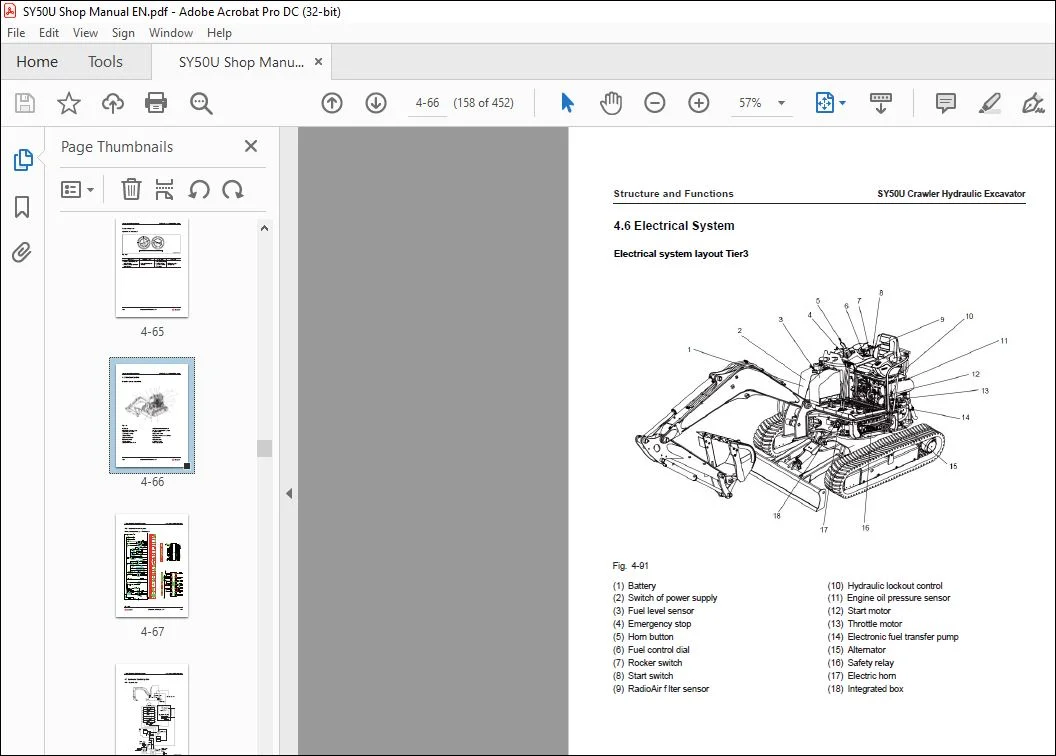
46 Electrical System 4-66
461 Electrical circuit diagram 4-67
47 Electronic Control System 4-68
471 General view 4-68
472 Functional overview of electrical control system 4-69
473 Valve control function 4-71
474 preheating and overheating protection function 4-73
475 Travel speed selection 4-74
476 Machine monitoring system 4-75
SY50U Crawler Hydraulic Excavator Table of Contents
Shop Manual – February 2017 V
5 Standard Values
51 Standard Values for Engine-Related Parts 5-3
52 Standard Values for Chassis-Related Parts 5-4
53 Standard Values for Electrical Parts 5-11
6 Testing and Adjusting
61 Engine Speed – Test 6-4
62 Exhaust Gas Color – Test 6-5
621 Using a hand tester 6-5
622 Using an instrument 6-6
63 Valve Clearance – Adjust 6-7
64 Compression Pressure – Test 6-8
65 Injection Timing – Test and Adjust 6-9
651 Checking injection timing 6-9
652 Adjusting the injection timing 6-12
66 Engine Oil Pressure – Test 6-13
67 Alternator Belt Tension – Test and Adjust 6-13
48 Integrated-controlled Monitor System 4-77
481 Monitor 4-77
482 Page introduction and operation 4-80
4821 Main menu 4-80
4822 Alert information 4-81
4823 History fault information 4-82
4824 System information 4-82
4825 Maintenance information 4-83
4826 GPS monitoring and rpm calibration 4-83
4827 Machine conf guration setup 4-84
4828 System lockout 4-85
4829 Password entry 4-86
48210 System lockout 4-87
48211 One-key call 4-88
Table of Contents SY50U Crawler Hydraulic Excavator
VI Shop Manual – February 2017
68 Hydraulic Pressure in Oil Circuits – Test and Adjust 6-14
69 LS Differential Pressure and LS Valve – Test/Adjust 6-16
691 Testing LS differential pressure 6-16
692 Adjusting LS valve 6-17
610 Hydraulic Pressure in Control Circuit – Test 6-18
611 Pilot Valve Output Pressure – Test 6-19
612 Work Equipment and Swing Pilot Valve – Adjust 6-20
613 Travel Deviation – Test 6-21
614 Oil Leakage – Test 6-22
6141 Work equipment cylinder 6-22
6142 Swing motor 6-24
6143 Travel motor 6-25
615 Residual Pressure in Hydraulic Circuit – Release 6-26
616 Swing Bearing Clearance – Check 6-27
617 Track Tension – Check and Adjust 6-28
6171 Checking track tension 6-28
6172 Adjusting track tension 6-28
61721 When the tension is high 6-28
61722 When the tension is low 6-29
618 Air Purging 6-30
6181 Purging air from hydraulic pump 6-30
6182 Purging air from hydraulic cylinder 6-31
6183 Purging air from swing motor 6-31
6184 Purging air from travel motor 6-31
7 Troubleshooting
71 Troubleshooting Precautions 7-3
72 Checks Before Troubleshooting 7-5
73 Connector Locations and System Diagrams 7-6
74 Number of Pins Required for Connection 7-9
75 Electric Wire Specif cations 7-16
76 How to Use the Judgement Chart 7-18
77 How to Use a Schematic Diagram for Troubleshooting 7-20
78 Troubleshooting the Electrical System 7-21
79 Troubleshooting the Engine 7-28
710 Troubleshooting the Hydraulic and Mechanical System 7-53
SY50U Crawler Hydraulic Excavator Table of Contents
Shop Manual – February 2017 VII
8 Disassembly and Assembly
81 Operating Precautions 8-6
82 Engine and Main Pump AS 8-9
821 Removal 8-10
822 Installation 8-14
83 Central Swivel Joint AS 8-15
831 Removal 8-15
832 Installation 8-16
833 Disassembly 8-17
834 Assembly 8-17
84 Sprocket 8-18
841 Removal 8-18
842 Installation 8-18
85 Travel Motor AS 8-19
851 Removal 8-19
852 Installation 8-20
853 Disassembly 8-21
8531 Preparatory work 8-21
8532 General precautions for disassembling 8-21
8533 Disassembling procedure 8-22
854 Table of maintenance standard 8-32
855 Assembly 8-35
8551 Preparatory work 8-35
8552 General precautions 8-35
8553 Assembly procedure 8-36
8554 Performance test 8-50
86 Swing Motor and Swing Mechanism AS 8-51
861 Removal 8-51
862 Installation 8-52
87 Swing Motor AS 8-53
871 Disassembly 8-53
8711 Separate the motor from the reducer 8-53
8712 Disassemble the motor 8-53
8713 Disassembling the reducer 8-59
Table of Contents SY50U Crawler Hydraulic Excavator
VIII Shop Manual – February 2017
8714 Assembling the motor 8-62
8715 Assemble the reducer 8-70
8716 Assembling the swing motor assembly 8-74
88 Swing Mechanism AS 8-75
881 Disassembly 8-75
882 Assembly 8-78
89 Swing Platform AS 8-82
891 Removal 8-82
892 Installation 8-84
810 Swing Bearing AS 8-85
8101 Removal 8-85
8102 Installation 8-85
811 Idler and Tension Spring AS 8-86
8111 Removal 8-86
8112 Installation 8-86
812 Tension Spring AS 8-87
8121 Disassembly 8-87
8122 Assembly 8-88
813 Idler AS 8-89
8131 Disassembly 8-89
8132 Assembly 8-89
814 Track Roller AS 8-90
8141 Removal 8-90
8142 Installation 8-90
815 Track Roller AS 8-91
8151 Disassembly 8-91
8152 Assembly 8-91
816 Carrier Roller AS 8-92
8161 Removal 8-92
8162 Installation 8-92
817 Track AS 8-93
8171 Removal 8-93
8172 Installation 8-93
SY50U Crawler Hydraulic Excavator Table of Contents
Shop Manual – February 2017 IX
818 Hydraulic Tank AS 8-94
8181 Removal 8-94
8182 Installation 8-94
819 Main Pump AS 8-95
8191 Removal 8-95
8182 Installation 8-95
820 Control Valve AS 8-96
8211 Removal 8-96
8212 Installation 8-96
821 Oil Source Control Valve AS 8-97
8221 Removal 8-97
8222 Installation 8-97
822 Left Pilot Valve AS (Arm and Swing Control) 8-98
8221 Removal 8-98
8222 Installation 8-98
823 Right Pilot Valve (Boom and Bucket Control) 8-99
8231 Removal 8-99
8232 Installation 8-99
824 Work Equipment Pilot Valve AS 8-100
8241 Disassembly 8-100
8242 Assembly8-101
825 Travel Pilot Valve AS 8-102
8251 Removal 8-102
8252 Installation 8-102
826 Travel Pilot Valve AS 8-103
8261 Disassembly8-103
8262 Assembly8-103
827 Boom Cylinder AS 8-104
8271 Removal 8-104
8272 Installation 8-105
828 Arm Cylinder AS 8-106
8281 Removal 8-106
8282 Installation 8-107
829 Bucket Cylinder AS 8-108
8291 Removal 8-108
8292 Installation 8-109
Table of Contents SY50U Crawler Hydraulic Excavator
X Shop Manual – February 2017
830 Def ection Cylinder AS 8-110
8301 Removal 8-110
8302 Installation 8-110
831 Dozer Blade Cylinder AS 8-111
8311 Removal 8-111
8312 Installation 8-112
832 Hydraulic Cylinder AS 8-113
8321 Disassembly 8-113
8322 Assembly 8-116
833 Work Equipment AS 8-119
8331 Removal 8-119
8332 Installation 8-120
834 Bucket-Arm AS 8-121
8341 Removal 8-121
8342 Installation 8-122
835 Bucket AS 8-123
8351 Removal 8-123
8352 Installation 8-124
836 Arm AS 8-125
8361 Removal 8-125
8362 Installation 8-126
837 Boom AS 8-127
8371 Removal 8-127
8372 Installation 8-128
8381 Removal 8-129
8382 Installation 8-129
8383 Installation 8-130
839 Dozer Blade AS 8-131
8391 Removal 8-131
8392 Installation 8-131
840 Cab AS 8-132
8401 Removal 8-132
SY50U Crawler Hydraulic Excavator Table of Contents
Shop Manual – February 2017 XI
9 Maintenance Standard
91 Swing Mechanism 9-3
92 Swing Bearing 9-4
93 Track Frame 9-5
94 Idler 9-6
95 Track Roller 9-7
96 Rubber track 9-8
97 Work Equipment 9-9
98 Arm Dimensions9-11
99 Bucket Dimensions 9-12
910 Hydraulic Cylinder 9-13
10 System Schematics
101 Hydraulic Circuit Diagram 10-3
102 General System Diagram (1/5) 10-4
103 General System Diagram (2/5) 10-5
104 General System Diagram (3/5) 10-6
105 General System Diagram (4/5) 10-7
106 General System Diagram (5/5) 10-8
107 Electrical Circuit Diagram 10-9
8412 Installation 8-133
842 Monitor AS 8-134
8421 Removal 8-134
8422 Installation 8-134
Table of Contents SY50U Crawler Hydraulic Excavator
XII Shop Manual – February 2017
Introduction
Introduction
Shop Manual – February 2017
SY50U Crawler Hydraulic Excavator
1-1
1 Introduction
11 How to Read the Manual 1-3
111 Shop manual organization 1-3
112 Revision and distribution 1-4
113 Symbols 1-5
114 Units 1-5
12 Technical Terms 1-6
121 Standard size and tolerance 1-6
122 Standard clearance and value 1-7
123 Standard interference 1-7
124 Repair limit and allowable value 1-8
125 Clearance limit 1-8
126 Interference limit 1-8
13 Handling Electrical and Hydraulic Components 1-9
131 Points to remember when handling electric components 1-9
1311 Handling wiring harnesses and connectors 1-9
1312 Main failures occurring in wiring harness 1-10
1313 Removing, installing, and drying connectors and wiring harnesses 1-12
1314 Handling the integrated control monitor 1-16
1315 Electric circuits troubleshooting precautions 1-17
132 Points to remember when handling hydraulic equipment 1-18
1321 Be careful of the operating environment 1-18
1322 Disassembly and maintenance work in the f eld 1-18
1323 Sealing openings 1-18
1324 Do not let any dirt or dust get in during ref lling operations 1-19
1325 Change hydraulic oil when the temperature is high 1-19
Introduction
1-2 Shop Manual – February 2017
SY50U Crawler Hydraulic Excavator
1326 Flushing operations 1-19
1327 Cleaning operations 1-20
14 Hose Connector 1-20
141 Type of hose connector 1-21
142 Hose connector tightening torque table 1-21
143 Connection of O-rings 1-22
15 Table of Standard Tightening Torques 1-23
16 Type of Bolts 1-24
17 Tightening Sequence 1-24
18 Maintenance of Half Flanges 1-25
181 Table of tightening torques for half f ange bolts 1-25
182 Temperature 1-31
Need help? Contact: [email protected]
https://vimeo.com/740669735
PLEASE NOTE:
- This is not a physical manual but a digital manual – meaning no physical copy will be couriered to you. The manual can be yours in the next 2 mins as once you make the payment, you will be directed to the download page IMMEDIATELY.
- This is the same manual used by the dealers inorder to diagnose your vehicle of its faults.
- Require some other service manual or have any queries: please WRITE to us at [email protected]
S.M