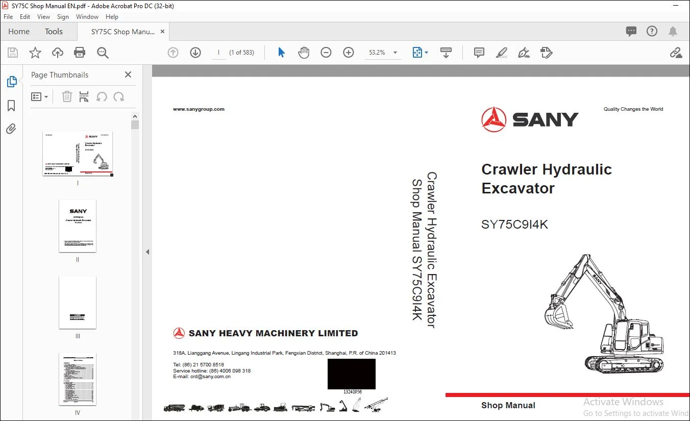
Sany SY75C914K Crawler Hydraulic Excavator Shop Manual – PDF DOWNLOAD
Original price was: $89.00.$30.95Current price is: $30.95.
Sany SY75C914K Crawler Hydraulic Excavator Shop Manual – PDF DOWNLOAD
Description
Sany SY75C914K Crawler Hydraulic Excavator Shop Manual – PDF DOWNLOAD
IMAGES PREVIEW OF THE MANUAL:
DESCRIPTION:
Sany SY75C914K Crawler Hydraulic Excavator Shop Manual – PDF DOWNLOAD
1 INTRODUCTION
1.1 How to Read the Shop Manual
1. Composition of shop manual
This shop manual contains the necessary technical information for services performed in a workshop.
For ease of understanding, the manual is divided into the following sections.
Introduction
This section provides an overview of what is covered in the rest of this manual and how to use
this manual,.
Shop Safety
This section covers basic shop safety information relating to this equipment. It also describes
what the hazard alerts mean that are used throughout the manual.
Specifi cations
Technical specif cation of work equipment and optional parts are given in this section.
Structure and function
This section explains the structure and function of each component. It helps the reader to get a
better understanding of the machine structure, and also serves as a reference for troubleshooting.
Standard Values
This section explains the standard values for a new machine and judgement criteria for testing,
adjusting, and troubleshooting. This standard value table is used to check the standard values in
testing and adjusting and to judge parts in troubleshooting.
Testing and adjusting
This section details the inspection before and after repair work as well as the adjustment during
inspection and repair work. Troubleshooting table that involves “Fault”and “Cause”are also included
in this section.
Troubleshooting
This section explains the way to detect faulty parts and the method to repair them. This section is
divided into the following parts: Electrical system, Engine, Hydraulic and mechanical system and
Monitoring system.
Disassembly and assembly
This section explains the procedures as well as precautions for removing, installing, disassembling
and assembling of each component.
TABLE OF CONTENTS:
Sany SY75C914K Crawler Hydraulic Excavator Shop Manual – PDF DOWNLOAD
1 Introduction
11 How to Read the Shop Manual 1-3
12 Terms for Maintenance Standard 1-5
13 Handling Electrical and Hydraulic Components 1-7
131 Points to remember when handling electric components 1-7
132 Points to remember when handling hydraulic equipment 1-16
14 Hose Connector 1-18
141 Type of hose connector 1-19
142 Hose connector tightening torque table 1-19
143 Connection of O-rings 1-20
15 Table of Standard Tightening Torques 1-21
16 Type of Bolts 1-22
17 Tightening Sequence 1-22
18 Maintenance of Half Flanges 1-23
181 Table of tightening torques for half f ange bolts 1-23
19 Conversion Table 1-24
2 Shop Safety
21 Hazard Alert Information 2-3
22 General Shop Safety 2-6
221 Rules and shop behavior 2-7
222 Housekeeping 2-7
223 Shop Liquids Storage 2-8
224 Cleaning Parts 2-8
225 Jacking Up the Machine 2-9
226 Electrical Dangers 2-9
227 Removing Attachments 2-10
228 Cleaning the Machine 2-10
229 Using the Correct Tools 2-10
2210 Hoisting a Load 2-11
2211 Appropriate Working Apparel 2-12
2212 Safety Partners 2-12
2213 Two people when engine running 2-13
2214 Driving Pins 2-13
2215 Aligning Parts or Components 2-14
2216 Fire Extinguisher and Emergency Exits 2-14
2217 Personal Protective Equipment 2-14
2218 Running the Machine 2-15
2219 Accumulator 2-16
2220 Adding Fluids to a System 2-16
2221 Track Recoil Springs 2-17
2222 High-Pressure Fluid Lines 2-17
2223 Safe Work Preparations 2-18
2224 Mounting and Dismounting 2-19
2225 Battery Hazards 2-20
2226 Jump-Start Safety 2-21
2227 Disconnecting the System Power 2-21
2228 Lockout/tagout 2-22
2229 Sequence of Procedures 2-22
2230 Chemical hazard 2-24
2231 Material Safety Data Sheets (MSDS) 2-24
23 Precautions for sling work and giving signals 2-25
3 Specifi cations
31 Dimension Drawings 3-3
32 Working Ranges 3-4
33 Technical Specif cations 3-5
34 Weight Table 3-6
35 Fuel and Coolant Capacity 3-8
36 Engine Performance Curve 3-9
4 Structure and Function
41 Engine and Cooling System 4-3
411 Radiator, oil cooler and intercooler 4-3
412 PTO 4-4
413 Engine control unit 4-5
42 Power Train 4-7
421 Power transmission system 4-7
422 Swing bearing 4-8
423 Swing mechanism 4-9
43 Undercarriage and Frame 4-10
431 Track frame 4-10
432 Idler wheel tensioner 4-11
44 Hydraulic System 4-13
441 Layout of hydraulic lines 4-13
441 Hydraulic circuit diagram 4-14
442 Hydraulic tank 4-15
443 Hydraulic pump 4-16
4431 Main pump 4-17
4432 Regulation of pressure, f ow and power 4-20
444 Control valve 4-27
4441 General 4-27
4442 External view 4-28
4443 Section view 4-29
445 Oil source control valve 4-30
446 Load sensitive system 4-32
4461 Load sensitive system 4-32
4462 Basic principle 4-33
4463 Operation of each function 4-35
4464 Operation of the whole system 4-47
447 Swing motor 2-57
448 Safety valve 2-58
449 Swing brake 2-60
4410 Central swivel joint 2-61
4411 Travel motor 2-63
4412 Travel motor operating process 2-65
4413 Parking brake operating process 2-67
4414 Counterbalance valve operating process 2-68
4415 Control system 2-70
4416 Work equipment and swing pilot valve 2-71
4417 Travel pilot valve 2-76
4418 Hydraulic breaker pilot valve 2-77
4419 Dozer blade pilot valve 2-81
4420 Anti-blast valve 2-85
4421 Hydraulic cylinder 2-86
4422 Work equipment 2-87
45 Electrical Control System 2-88
451 General 2-88
452 Diagram of electrical control system 2-89
453 Diagram of electrical circuit 2-90
454 Engine control function 2-91
455 Valve control function 2-93
456 Auto deceleration function 2-94
457 Auto preheating and overheating protection function 2-95
458 Travel control function 2-97
46 Integrated Control Monitoring System 2-99
461 Monitor 2-99
462 Monitor introduction 2-102
463 Monitor operation 2-104
5 Standard Values
51 Standard Values for Engine-Related Parts 5-3
52 Standard Values for Chassis-Related Parts 5-4
53 Standard Values for Electrical Parts 5-10
6 Testing and Adjusting
61 Engine Speed – Test 6-3
62 Exhaust Gas Color – Test 6-4
621 Test with a portable smoke tester 6-4
622 Test with a smokemeter 6-4
63 Valve Clearance – Adjust 6-6
64 Compression Pressure – Test 6-8
65 Injection Timing – Test and Adjust 6-9
66 Oil Pressure – Test 6-11
67 Alternator Belt Tension – Test and Adjust 6-12
671 Testing 6-12
672 Adjusting 6-12
68 Fuel Control Lever – Adjust 6-13
69 Hydraulic Pressure in Oil Circuits – Test and Adjust 6-14
691 Testing 6-14
692 Adjusting the main relief valve 6-14
610 LS Differential Pressure and Flow Control Valve – Test and Adjust 6-15
6101 Measure LS differential pressure 6-15
6102 Adjust f ow control valve 6-15
611 Hydraulic Pressure in Control Circuit – Test 6-16
612 Solenoid Valve Outlet Pressure – Test 6-17
613 Pilot Valve Output Pressure – Test 6-18
614 Work Equipment and Swing Pilot Valve – Adjust 6-19
615 Travel Deviation – Test 6-20
616 Internal Oil Leakage – Test 6-21
6161 Work equipment cylinder 6-21
6162 Swing motor 6-23
6163 Travel motor 6-23
617 Residual Pressure in Hydraulic Circuit – Relieve 6-24
618 Swing Bearing Clearance – Check 6-24
619 Track Tension – Check and Adjust 6-25
6191 Checking 6-25
6192 Adjusting 6-26
620 Air Bleeding 6-27
7 Troubleshooting
71 Troubleshooting Precautions 7-3
72 Electric Circuit Troubleshooting Precautions 7-5
73 Checks Before Troubleshooting 7-6
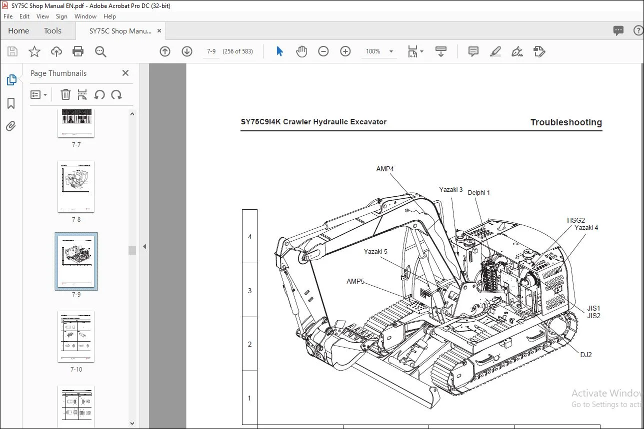
74 Connector Locations and System Circuit Diagram 7-7
75 Number of Pins Required For Connection 7-10
76 Troubleshooting with a Fault Code 7-16
77 Failure Mode and Diagnostic Chart 7-17
771 How to use the diagnostic chart 7-19
772 How to use troubleshooting table 7-20
78 Troubleshooting of Electrical System 7-21
79 Troubleshooting of Engine 5-28
710 Troubleshooting of Hydraulic and Mechanical System 5-55
711 Troubleshooting of Machine Monitoring System 5-81
8 Disassembly and Assembly
81 Operation Precautions 8-7
82 Engine and Main Pump AS – Removal and Installation 8-11
821 Removal 8-11
822 Installation 8-17
83 Radiator AS – Removal and Installation 8-18
831 Removal 8-18
832 Installation 8-20
84 Fuel Tank AS – Removal and Installation 8-21
841 Removal 8-21
842 Installation 8-22
85 Swivel Joint AS – Removal and Installation 8-23
851 Removal 8-23
852 Installation 8-24
86 Swivel Joint AS – Disassembly and Assembly 8-25
861 Disassembly 8-25
862 Assembly 8-25
87 Sprocket – Removal and Installation 8-26
871 Removal 8-26
872 Installation 8-27
88 Travel Motor AS – Removal and Installation 8-28
881 Removal 8-28
882 Installation 8-29
89 Disassembly and Assembly of Travel Motor (GM09VN) 8-30
891 Sectional view of the travel motor assembly 8-30
892 Exploded view of reducer assembly 8-32
893 Exploded view of hydraulic motor assembly 8-33
894 Parts catalogue 8-34
895 Tools 8-35
896 Tightening torques 8-42
897 Table of weights 8-42
898 Disassembly 8-43
899 Table of maintenance standard 8-69
8910 Assembly 8-71
8911 Table of dimensions for clearance adjustable parts 8-98
8912 Conf rmation of performance test 8-99
810 Swing Motor and Swing Mechanism AS – Removal and Installation 8-100
8101 Removal 8-100
8102 Installation 8-101
811 Swing Motor AS – Disassembly and Assembly 8-102
8111 Disassembly 8-102
8112 Assembly 8-110
812 Swing Mechanism AS – Disassembly and Assembly 8-119
8121 Disassembly8-119
8122 Assembly 8-122
813 Swing Platform AS – Removal and Installation 8-126
8131 Removal 8-126
8132 Installation 8-128
814 Swing Bearing AS – Removal and Installation 8-129
8141 Removal 8-129
8142 Installation 8-129
815 Idler Wheel and Tension Spring AS – Removal and Installation 8-130
8151 Removal 8-130
8152 Installation 8-130
816 Tension Spring AS – Disassembly and Assembly 8-131
8161 Disassembly 8-131
8162 Assembly 8-133
817 Idler Wheel AS – Disassembly and Assembly 8-134
8171 Disassembly 8-134
8172 Assembly 8-135
818 Track Roller AS – Removal and Installation 8-138
8181 Removal 8-138
8182 Installation 8-139
819 Track Roller AS – Disassembly and Assembly 8-140
8191 Disassembly 8-140
8192 Assembly 8-143
820 Carrier Roller AS – Removal and Installation 8-146
8201 Removal 8-146
8202 Installation 8-146
821 Track Shoe AS – Removal and Installation 8-147
8211 Removal 8-147
8212 Installation 8-148
822 Hydraulic Tank AS – Removal and Installation 6-149
8221 Removal 6-149
8222 Installation 6-151
823 Main Pump AS – Removal and Installation 6-152
8231 Removal 6-152
8232 Installation 6-153
824 Main Pump Input Shaft Oil Seal – Removal and Installation 6-154
8241 Removal 6-154
8242 Installation 6-154
825 Control Valve AS – Removal and Installation 6-155
8251 Removal 6-155
8252 Installation 6-156
826 Control Valve AS – Disassembly and Assembly 6-157
8261 Disassembly 6-157
8262 Assembly 6-162
827 Oil Source Control Valve AS – Removal and Installation 6-168
8271 Removal 6-168
8272 Installation 6-169
828 Left Pilot Valve AS – Removal and Installation 6-170
8281 Removal 6-170
8282 Installation 6-170
829 Right Pilot Valve AS – Removal and Installation 6-171
8291 Removal 6-171
8292 Installation 6-171
830 Work Equipment Pilot Valve AS – Disassembly and Assembly 6-172
8301 Disassembly 6-172
8302 Assembly 6-173
831 Travel Pilot Valve AS – Removal and Installation 6-175
8311 Removal 6-175
8312 Installation 6-175
832 Travel Pilot Valve AS – Disassembly and Assembly 6-176
8322 Disassembly 6-176
8321 Assembly 6-176
833 Boom Cylinder AS – Removal and Installation 6-177
8331 Removal 6-177
8332 Installation 6-178
834 Arm Cylinder AS – Removal and Installation 6-179
8341 Removal 6-179
8342 Installation 6-180
835 Bucket Cylinder AS – Removal and Installation 6-182
8351 Removal 6-182
8352 Installation 6-183
836 Dozer blade Cylinder AS – Removal and Installation 6-185
8361 Removal 6-185
8362 Installation 6-186
837 Hydraulic Cylinder AS – Disassembly and Assembly 6-187
8371 Disassembly 6-187
8372 Assembly 6-191
838 Work Equipment AS – Removal and Installation 6-194
8381 Removal 6-194
8382 Installation 6-195
839 Bucket AS – Removal and Installation 6-197
8391 Removal 6-197
8392 Installation 6-198
840 Arm AS – Removal and Installation 6-199
8401 Removal 6-199
8402 Installation 6-200
841 Bucket and Arm AS – Removal and Installation 6-201
8411 Removal 6-201
8412 Installation 6-202
842 Boom AS – Removal and Installation 6-203
8421 Removal 6-203
8422 Installation 6-205
843 Blade AS – Removal and Installation 6-206
8431 Removal 6-206
8432 Installation 6-207
844 Cab AS – Removal and Installation 6-208
8441 Removal 6-208
8442 Installation 6-211
845 Counterweight AS – Removal and Installation 6-212
8451 Removal 6-212
8452 Installation 6-213
846 Monitor – Removal and Installation 6-214
8461 Removal 6-214
8462 Installation 6-214
9 Maintenance Standard
91 Swing Mechanism 9-3
92 Swing Bearing 9-4
93 Track Frame 9-5
94 Idler Wheel 9-6
95 Track Roller 9-7
96 Track Shoe 9-8
97 Control Valve 9-10
98 Oil Source Control Valve 9-11
99 Swing Motor 9-12
910 Work Equipment and Swing Pilot Valve 9-13
911 Travel Pilot Valve 9-14
912 Work Equipment 9-15
9121 Work equipment dimension 9-17
913 Hydraulic Cylinder 9-19
10 Miscellaneous
101 Hydraulic Line Layout 10-3
102 Hydraulic Circuit Diagram 10-4
103 Overall System Diagram (1/5) 10-5
104 Overall System Diagram (2/5) 10-6
105 Overall System Diagram (3/5) 10-7
106 Overall System Diagram (4/5) 10-8
107 Overall System Diagram (5/5) 10-9
108 Electrical Circuit Diagram 10-10
1 Introduction
11 How to Read the Shop Manual 1-3
12 Terms for Maintenance Standard 1-5
13 Handling Electrical and Hydraulic Components 1-7
131 Points to remember when handling electric components 1-7
132 Points to remember when handling hydraulic equipment 1-16
14 Hose Connector 1-18
141 Type of hose connector 1-19
142 Hose connector tightening torque table 1-19
143 Connection of O-rings 1-20
15 Table of Standard Tightening Torques 1-21
16 Type of Bolts 1-22
17 Tightening Sequence 1-22
18 Maintenance of Half Flanges 1-23
181 Table of tightening torques for half f ange bolts 1-23
19 Conversion Table 1-24
Contact us: [email protected]
https://vimeo.com/740675762
PLEASE NOTE:
- This is the SAME exact manual used by your dealers to fix your vehicle.
- The same can be yours in the next 2-3 mins as you will be directed to the download page immediately after paying for the manual.
- Any queries / doubts regarding your purchase, please feel free to contact [email protected]
S.M