SciCan Statim 2000 5000 5000S Cassette Autoclave Service Manual PDF
Original price was: $95.00.$30.95Current price is: $30.95.
Official SciCan confidential service manual for the STATIM L (2000), STATIM 5000, and STATIM 5000S Cassette Autoclaves (PN 96-103912 Rev. 3.0). Covers complete cycle fault troubleshooting (32+ fault codes), hardware fault diagnosis, triac and load testing, all component removal and replacement (pump, steam generator, solenoid valve, controller board, microprocessor/EEPROM, compressor, armature), thermocouple and pressure transducer calibration, controller board schematics, and full spare parts list. 235 pages — instant PDF download.
Description
SciCan Statim 2000 5000 5000S Cassette Autoclave Service Manual PDF DOWNLOAD
DESCRIPTION:
SciCan STATIM L / 5000 / 5000S — Official Confidential Service Manual (96-103912 Rev. 3.0)
This is the complete official SciCan confidential service manual for the STATIM L (2000), STATIM 5000, and STATIM 5000S Cassette Autoclaves — the three-model service reference used exclusively by SciCan-certified service technicians. Published by SciCan (Toronto, Ontario, Canada — PN 96-103912 Rev. 3.0), this modular document compiles all individual service chapter revisions into a single 235-page technical reference. It is the authoritative guide for diagnosing and repairing every system in these widely deployed dental and medical office sterilizers.
📋 File Details
| Detail | Information |
|---|---|
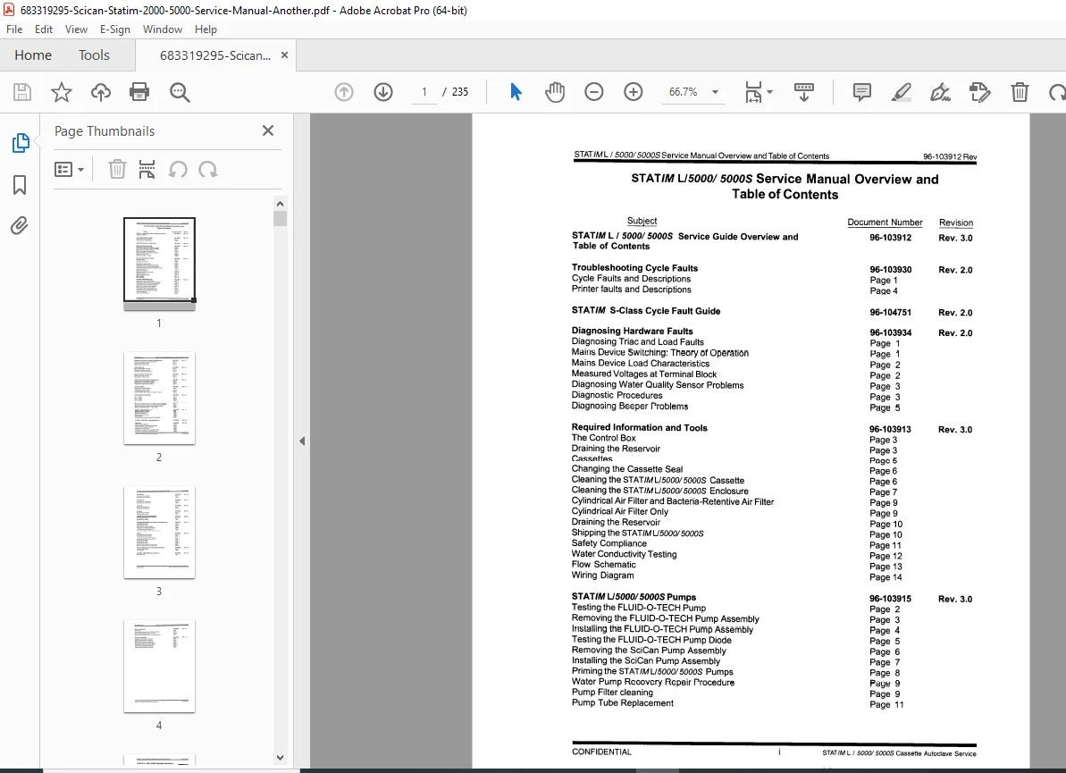
| Manual Name | STATIM L / 5000 / 5000S Service Manual Overview and Table of Contents |
| Publication Number | 96-103912 Rev. 3.0 |
| Models Covered | STATIM L (2000), STATIM 5000, STATIM 5000S |
| Publisher | SciCan Inc., Toronto, Ontario, Canada |
| PDF Created | June 2004 |
| PDF Quality | Scanned, high-resolution, professionally digitized |
| Total Pages | 235 |
| File Format | PDF (US Letter, 612×792 pts) |
📑 Complete Table of Contents
This manual is organized into numbered technical sections, each with its own document number and revision:
Service Manual Overview and Table of Contents (96-103912 Rev. 3.0)
- About the service guide (scope, regulatory obligations, safety symbols)
- Illustrated component identification diagram (29 labeled components — fascia, LCD, keypad, cassette, printer, power cord, air filter, drain tube, bubble level, reservoir cap, controller board, armature, compressor, steam generator, microswitch, thermocouples, water quality sensor, pump assembly, exhaust solenoid valve, probe bracket, check valve, biological filter, cover, chassis, transducer, pressure interface board)
- Document change record
Troubleshooting — Cycle Faults (96-103930 Rev. 2.0)
- Complete Cycle Fault Code Reference — Faults #1 through #32+ with description and suggested corrective steps:
- Fault #1 — Cassette temperature failed to reach 99°C; probable cause: blown thermal fuse, faulty steam generator triac/compressor triac in conjunction with cassette leak, large load in cassette
- Fault #2 — Cassette temperature failed to increase from 95°C to 100°C; probable causes: faulty cassette seal, damaged cassette, miscalibration
- Fault #3 — Cassette failed to pressurize; probable causes: faulty cassette seal, failed solenoid valve installation, miscalibration
- Fault #4 — Cassette temperature above 130°C during sterilization phase; probable causes: worn/damaged cassette, improperly installed copper tubing fitting, faulty valve, miscalibration (verify 2.520V ±0.001V)
- Fault #5 — Pump failed to push water into steam generator; probable causes: leaking solenoid outlet valve, weak pump, steam generator inlet tube blockage, early activation of steam in steam generator
- Fault #6 — Steam generator temperature 5°C less than chamber 22 seconds after purge in seizing phase; possible causes: faulty steam generator thermocouple, disconnected thermocouple lead, faulty PCB
- Fault #7 — Cassette temperature dropped below setpoint during conditioning phase; probable causes: bad/worn cassette seal, faulty thermocouple replacement/calibration need
- Fault #8 — Cassette temperature dropped during wrapped or unwrapped cycle (steam generator 5°C less than chamber temperature); indicates temperature measurement system problem
- Fault #9 — Software failed to detect need to pump water within 90 seconds; probable causes: blocked steam generator inlet tube, failed water pump, failed steam generator triac or pump triac, faulty solenoid valve installation
- Fault #10 — N/A (reserved)
- Fault #12 — N/A
- Faults #14–15 — Cassette temperature failed to drop during conditioning phase or failed to drop at end of drying
- Faults #16–18 — Steam generator temperature measurement faults
- Faults #19–20 — Steam generator/chamber temperature out of range
- Faults #21–24 — Reserved
- Faults #25–27 — S-Class additional cycle fault conditions (STATIM 5000S)
- Fault #32 — Printer fault: printer not printing or message not displayed (paper jam, defective printer controller board, defective printer mechanism)
- Printer Faults and Descriptions
- STATIM S-Class Cycle Fault Guide (96-104751 Rev. 2.0) — additional fault codes specific to 5000S models
Diagnosing Hardware Faults (96-103934 Rev. 2.0)
- Diagnosing Triac and Load Faults
- Mains device switching: Theory of operation (68HC705Cx microcontroller Port A, auxiliary latch U12-74HC273, open-drain hex inverter U7-74HCO05, optoisolated triac drivers U1–U4, four diagnostic LEDs CR5/CR6/CR7/CR10)
- Mains device load characteristics:
- Steam Generator — resistive load
- Water Pump — ½-wave rectified with internal diode
- Exhaust Valve — full-wave rectified with internal diode bridge
- Compressor — ½-wave rectified with internal diode
- Measured Voltages at Terminal Block — complete table of AC/DC voltages for all four device terminal pairs (J1-3 through J1-10) in ON/OFF states
- Diagnosing Water Quality Sensor Problems
- Water quality specification: ≤5 ppm TDS / conductivity <10 μS/cm
- Four failure modes: always empty, always good water, always poor water, random readings
- Diagnostic procedure: probe terminal checks (J4-3/J4-4), float terminal checks (J4-5/J4-6), Controller Board inspection
- Diagnosing Beeper Problems
Required Information and Tools (96-103913 Rev. 3.0)
- The Control Box (SciCan diagnostic tool, connections to P1/P2/P3/P4)
- Draining the Reservoir (illustrated step-by-step)
- Cassettes: changing cassette seal, cleaning STATIM L/5000/5000S cassette (STAT-DRI application, SciCan Part #202473/802473)
- Cleaning the enclosure
- Air Flow Diagram (cylindrical air filter + bacteria-retentive filter — change every 500 cycles or 6 months)
- Cylindrical air filter replacement procedure
- Shipping the unit
- Safety Compliance:
- Dielectric Strength Test (Hi-Pot): 1500 VAC RMS (North America/Japan), 2200 VAC RMS (Europe EN 61010), 50/60 Hz, 2-second rise time, 2-second duration minimum
- Protective Earth Impedance Test (Ground Continuity)
- Water Conductivity Testing (SciCan conductivity meter PN 01-103139S; max 5 ppm / <10 μS/cm; test at room temperature)
- Flow Schematic (complete hydraulic circuit diagram)
- Wiring Diagram
Pumps (96-103915 Rev. 3.0)
- FLUID-O-TECH Pump:
- Testing the pump
- Removing / installing the FLUID-O-TECH pump assembly
- Testing the FLUID-O-TECH pump diode
- SciCan Pump:
- Removing / installing the SciCan pump assembly (with disconnection of transducer connector, compression nut, Teflon™ tube to steam generator inlet, cable tie/inlet tube, fast-on terminals, shoulder screws and rubber brackets — Loctite LM113 on reassembly)
- Priming STATIM L/5000/5000S pumps
- Water Pump Recovery Repair Procedure:
- Pump filter cleaning (vinegar soak for scale; every 500 cycles/6 months; mesh filter at inlet fitting, fine mesh filter insert in outlet right-angle fitting)
- Pump tube replacement
- Replacement Tube Kits — Chart A (nominal orifice diameters: 100V = 0.0275″, 115V = 0.0265″, 230V = 0.0250″)
- Pump Test Parameters — Chart B (FLUID-O-TECH and SciCan pump flow times in seconds at 100V/50Hz, 100V/60Hz, 110V/60Hz, 230V/50Hz)
Solenoid Valve Repair, Removal and Replacement (96-103919 Rev. 2.0)
- Inspecting and repairing the solenoid valve
- Removing the solenoid valve
- Replacing the solenoid valve
Steam Generator (96-103920 Rev. 3.0)
- Removing / replacing the steam generator
- The Steam Generator Check Valve (removal and replacement)
- Steam Generator Thermal Fuse (removing and replacing)
Probe Bracket and Chamber Thermocouple (96-103916 Rev. 3.0)
- Removing / replacing the probe bracket assembly
- Aligning the probe bracket assembly
Controller Board (96-103917 Rev. 2.0)
- Removing / replacing the Controller Board
- Controller Board Fuse Values
- Controller Board High Voltage J1 Connector — Chart A (pin assignments)
- Controller Board Schematics — all four PCB revisions:
- Rev. 1.0 PCB schematic
- Rev. 2.0 PCB schematic
- Rev. 2.4 PCB schematic
- Rev. 2.9 PCB schematic
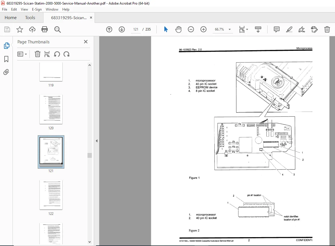
Microprocessor (96-103923 Rev. 2.0)
- Removing the Microprocessor and preprogrammed EEPROM
- Replacing the Microprocessor (both devices socketed) (IC socket U14 for 40-pin 68HC705Cx, IC socket U8 for EEPROM; pin #1 orientation critical; matched pair — continuous beep if either substituted alone)
- Replacing the Microprocessor — 110V Canada (special 2-chip EEPROM programming procedure using white-dot programming chip)
- Post-installation verification: software version number on LCD, recalibration requirement
STATIM L / 5000 / 5000S Software (96-103936 Rev. 2.0)
- Identifying software versions
- Version 2 visible changes
- New service features (printing last cycle for intermittent fault diagnosis via START button without selecting cycle)
- New cycle fault conditions (Faults 20–27)
- STATIM 5000S: Controller Board and microprocessor compatibility
- STATIM L/5000/5000S Language Selection (96-103928 Rev. 2.0) — language change via WRAPPED/UNWRAPPED keypad hold at power-on
Calibration (96-103929 Rev. 2.0)
- Thermocouple Calibration — general procedure
- Steam Generator Thermocouple Calibration (automated calibration cycle)
- Chamber Thermocouple Calibration (Vref potentiometer adjustment to 2.520V ±0.001V; hexadecimal offset values displayed upper right/left LCD during calibration mode; calibration jumper on Controller Board header W1)
- Calibration of S-Class Units (STATIM 5000S): — full procedure including pressure transducer
- Procedure without Dresser meter (temperature reference only)
- Procedure with Dresser meter (RTD + compression fitting into calibration cassette; quick-connect pressure port; DC Vref setup; potentiometer adjustment; chamber thermocouple/pressure transducer calibration cycle using UNWRAPPED button; 0.5 kPa per button press offset; leak check during pressurization)
Microswitch (96-103918 Rev. 2.0)
- Removing / replacing the microswitch
Compressor (96-103921 Rev. 3.0)
- Removing / replacing the compressor
Reservoir (96-103926 Rev. 2.0)
- Removing / replacing the reservoir
Armature (96-103927 Rev. 2.0)
- Removing / replacing the armature
Isoplate Removal and Replacement (96-103937 Rev. 2.0)
- Removing / replacing the isoplate
Cover Removal and Replacement (96-103914 Rev. 3.0)
- Removing / reinstalling the cover
- Replacing the armature gasket
- Removing and replacing the fascia
- LCD Removal and Replacement
- Membrane Keypad Removal and Replacement
Printer (96-103925 Rev. 3.0)
- Removing / replacing the printer module
- Removing / replacing the printer interface board
- Adjusting print quality
- Removing / replacing the printer mechanism
- Positioning the ferrite core
- Printer Interface Board important notes
- Printer Interface Board / Printer Board Schematics (96-103933 Rev. 2.0) — interface board schematic + printer board schematic
Mains Components (96-104748 Rev. 1.0)
- Line cords
- Removing and replacing the A.C. power switch
- Removing and replacing the line filter
- Removing and replacing the A.C. inlet receptacle
Pressure Transducer (96-104749 Rev. 1.0 — STATIM 5000S only)
- Checking / removing / replacing the pressure transducer
- Removing / replacing the pressure interface board
- Removing and replacing the battery
- Pressure Interface Board Schematic
Spare Parts List (96-103931 Rev. 2.0)
- Complete spare parts list with SciCan part numbers (pumps, controller board/microprocessor kits, seals, filters, solenoid valves, steam generators, thermocouples, printer components, reservoir assemblies, armature gaskets)
⚡ Key Technical Specifications at a Glance
| Specification | Value |
|---|---|
| Models Covered | STATIM L (2000), STATIM 5000, STATIM 5000S |
| Sterilizer Type | Cassette Autoclave (steam-flush pressure-pulse) |
| Cycle Types | Wrapped, Unwrapped, Rubber/Plastic (S-Class) |
| Microcontroller | Motorola 68HC705Cx (40-pin DIP, socket U14) |
| EEPROM | Matched pair with microprocessor (socket U8) |
| Mains-Switched Devices | Steam generator, water pump, exhaust solenoid valve, compressor |
| Switching Technology | Optoisolated triacs (U1–U4); diagnostic LEDs CR5/CR6/CR7/CR10 |
| Voltage Ratings | 100V/50Hz, 100V/60Hz, 110V/60Hz (Canada), 230V/50Hz |
| Vref Calibration Voltage | 2.520V ±0.001V (Vref potentiometer on Controller Board) |
| Water Quality Limit | ≤5 ppm TDS / conductivity <10 μS/cm |
| Filter Change Interval | Every 500 cycles or 6 months |
| Pump Filter Maintenance | Every 500 cycles or 6 months (vinegar soak for scale) |
| Hi-Pot Test Voltage | 1500 VAC RMS (NA/Japan), 2200 VAC RMS (Europe EN 61010) |
| Pressure Calibration Step | 0.5 kPa per UNWRAPPED/WRAPPED button press (5000S) |
| Cycle Fault Codes | Faults #1–#32+ documented (including S-Class specific codes) |
| Controller Board Versions | Rev. 1.0, 2.0, 2.4, 2.9 schematics all included |
🔑 Why Biomedical / Dental Equipment Technicians Need This Manual
- ✅ Complete cycle fault code reference #1–#32+ — every code with root cause analysis and corrective action steps, including S-Class exclusive codes for the 5000S
- ✅ Triac and load diagnostics — terminal block voltage measurement table for all four mains devices (ON/OFF states) to isolate triac, optoisolator, or load failures without guesswork
- ✅ Controller Board schematics for all four PCB revisions (Rev. 1.0 through 2.9) — board-level fault isolation capability
- ✅ Printer Interface Board and Printer Board schematics — repair or replace the optional printer system
- ✅ Full thermocouple and pressure transducer calibration with and without Dresser meter — mandatory after replacing steam generator, probe bracket, transducer, controller board, or microprocessor
- ✅ Microprocessor/EEPROM replacement — matched pair installation procedure including special 110V Canada two-step EEPROM programming
- ✅ Pump tube sizing charts — correct orifice diameter by voltage rating to restore pump flow to specification
- ✅ Water quality sensor diagnosis — four failure modes with systematic test procedure using Controller Board terminals J4-3 through J4-6
- ✅ Complete spare parts list with SciCan part numbers — order exact OEM components
- ✅ Safety compliance procedures — dielectric strength (hi-pot) and ground continuity tests for post-service certification
💬 Sales Pitch
The STATIM is the most trusted cassette autoclave in dentistry — and when it throws a cycle fault at 7:30 AM before the first patient, you need answers fast. This complete SciCan confidential service manual gives you every fault code, every schematic, every calibration step, and every part number. Whether you’re diagnosing a Fault #3, replacing a controller board, or recalibrating after a steam generator swap — it’s all here. Download instantly after purchase