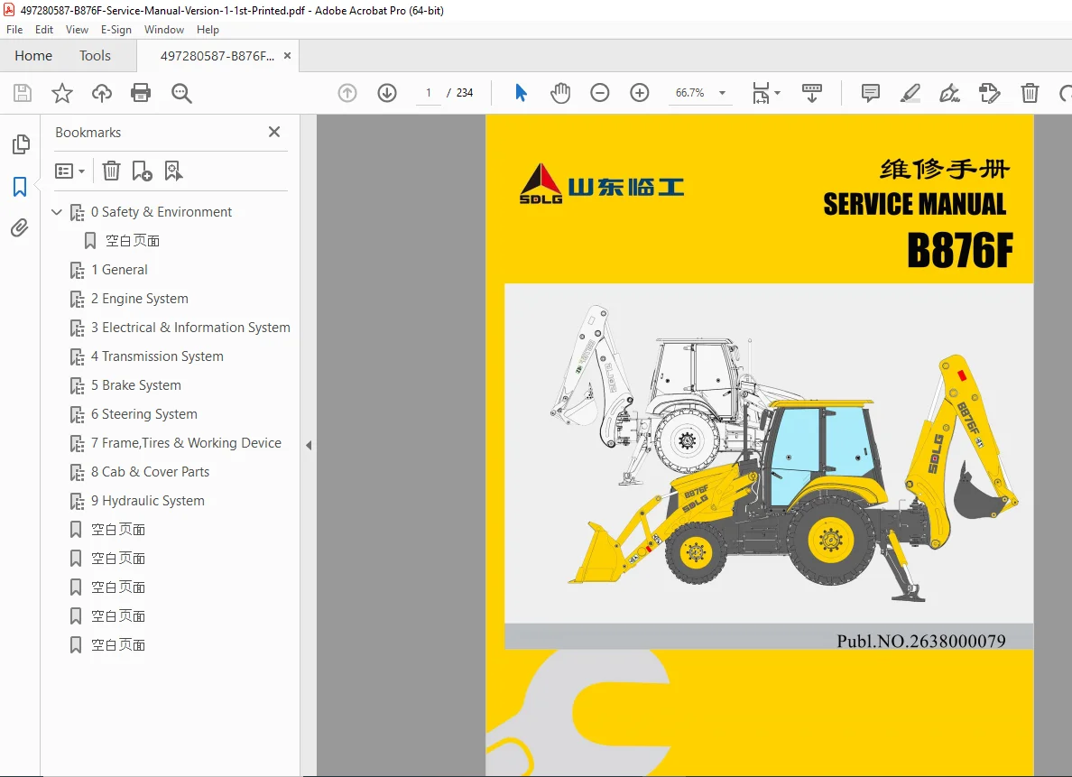
SDLG B876F Backhoe Loader Service Manual – PDF
Original price was: $95.00.$28.95Current price is: $28.95.
Complete 234-page factory service manual for SDLG B876F backhoe loader with YC4A105Z-T20 engine (75 kW). Comprehensive technical documentation covering engine system, ZF transmission, electrical circuits, brake system, load-sensing steering, hydraulic systems (loading/excavating/outrigger), cab and air conditioner, drive axles, torque converter maintenance, fault diagnosis, disassembly procedures, pressure testing, and complete specifications with wiring diagrams for professional service.
Description
SDLG B876F Backhoe Loader Service Manual Complete Repair Maintenance Guide PDF DOWNLOAD
DESCRIPTION
Official Factory Service Manual for SDLG B876F Backhoe Loader
This authentic SDLG service manual PDF provides complete factory-authorized technical documentation for servicing, repairing, and maintaining the B876F backhoe loader manufactured by Shandong Lingong Construction Machinery Co., Ltd. Essential for heavy equipment technicians, construction fleet mechanics, SDLG dealerships, and equipment operators responsible for this versatile backhoe loader machine.
FILE DETAILS
- Manual Name: SDLG B876F Backhoe Loader Service Manual
- Model Covered: B876F Backhoe Loader
- Manufacturer: Shandong Lingong Construction Machinery Co., Ltd.
- Version: Version 1, First Printing (July 2017)
- PDF Quality: Excellent – Factory diagrams and technical illustrations
- Total Pages: 234 pages
- Language: English
- Page Size: A4 (880×1230 mm format)
MACHINE OVERVIEW
The SDLG B876F is an overall frame tire backhoe loader that integrates loading and excavating mechanisms on a solid integral chassis. This multi-purpose, high-efficiency engineering machine is widely used in:
✓ Municipal construction and road maintenance
✓ Highway and water conservancy projects
✓ Power supply and water supply installations
✓ Forestry industry operations
✓ Farmland construction and pipe laying
✓ Cable laying and landscaping
✓ General construction and excavation work
KEY SPECIFICATIONS
Engine System:
- Model: YC4A105Z-T20
- Type: Inline, water-cooling, four-stroke, turbocharged, direct injection combustion chamber
- Rated Power: 75 kW (approximately 100 HP)
- Rated Speed: 2200 r/min
- Displacement: 4837 mL (4.84 liters)
- Engine Oil Capacity: 10 liters
Performance Parameters:
- Rated Capacity (Backhoe Bucket): 1.0 m³
- Rated Capacity (Excavation Bucket): 0.18 m³
- Rated Working Load: 1800 kg
- Maximum Tractive Force: 86 kN
- Maximum Excavation Force: 55 kN
- Breakout Force: 20 kN
- Maximum Gradeability: 30 degrees
Dimensions and Weight:
- Vehicle Length: 7243 mm
- Transport Height: 3608 mm
- Vehicle Width: 2265 mm
- Maximum Dumping Height: 2693 mm (45° unloading angle)
- Maximum Excavation Depth: 4352 mm
- Maximum Excavation Radius: 5393 mm
- Wheelbase: 2170 mm
- Tread (Front/Rear): 1928/1790 mm
- Work Quality: 7800 kg
Drive Speed (4-Speed Forward/Reverse):
- Gear I: Forward 5.9 km/h, Reverse 7.4 km/h
- Gear II: Forward 10.7 km/h, Reverse 13 km/h
- Gear III: Forward 21.4 km/h, Reverse 20 km/h
- Gear IV: Forward 37 km/h
COMPLETE SECTION BREAKDOWN
SECTION 0: SAFETY AND ENVIRONMENT (Pages 1-28)
Comprehensive Safety Guidelines:
- Preface and safety handling during machine operation
- Simple safety rules for all operations
- Pre-operation safety checks
- Mounting and dismounting procedures
- Seat belt usage requirements
- Safety during engine running
- Leaving operator’s seat procedures
- Towing and tow-start safety protocols
Repair and Maintenance Safety:
- Pre-repair safety checklist
- Maintenance position requirements
- Loading arm safety lever installation/removal
- Attachment safety notices
- Tire operation safety (air inflation, installation, repair)
- Battery operation safety (charging, booster start procedures)
- A/C refrigerant handling safety
- Personal protection devices
- Accident response measures
Hydraulic and Fluid Safety:
- Safe handling of oils and hydraulic fluids
- Pressure relief procedures
- Fire prevention measures
- Cleanliness requirements
- Electrical system safety
- Welding and grinding precautions
- Post-fire inspection procedures
Health Hazard Information:
- Working with paints, plastics, and rubbers
- Fluoride rubber handling
- Asbestos and toxic dust protocols
Transportation Safety:
- Loading and unloading procedures
- Ground transportation guidelines
- Lifting procedures with specifications (4 steel wires, minimum 7m length)
- Securing for ship/train transport
Environmental Protection:
- Waste treatment procedures (recycling, material recovery, energy recovery, disposal, burial)
- Engine oil and fluid disposal
- Filter disposal protocols
- Refrigerant handling (R134a)
- Chemical, rubber, and plastic disposal
- Electronic unit recycling
- Contaminated environment work procedures
- Decontamination after leakage/accidents
SECTION 1: GENERAL (Pages 1-1 to 1-14)
Introduction to Machine:
- Complete outline drawing with component identification:
- Loading hopper
- Boom at loading end
- Scoop cylinder
- Engine hood
- Boom cylinder at loading end
- Hydraulic fuel tank (left) / fuel tank (right)
- Tool box (left) / battery box (right)
- Cab
- Left/right outrigger
- Scoop cylinder
- Arm
- Excavator bucket
- Bucket cylinder
Performance Parameters Tables:
- Machine performance parameters (Table 0-1)
- Main dimensions and weight parameters (Table 0-2)
- Engine specifications (Table 0-3)
- Drive system specifications (Table 0-4)
- Steering system specifications (Table 0-5)
- Loading device specifications (Table 0-6)
- Excavation working device specifications (Table 0-7)
- Filling capacity specifications (Table 0-8)
Overall Dimensions:
- Detailed dimension drawings
- Turning radius: 4118 mm (horizontal passing radius 5350 mm)
- Minimum ground clearance: 346 mm
Technical Specifications:
- Standard tightening torque tables (Table 0-9)
- Bolt strength classes (4.6, 5.6, 6.8, 8.8, 10.9, 12.9)
- Torque specifications for bolt diameters 6-39mm
- Yield strength specifications (240-1080 N/mm²)
Tools Required:
- Special tools listing
- Service equipment requirements
Marking Systems:
- Component identification
- Serial number locations
Judgment Standards:
- Visual inspection criteria
- Measurement method determination
- Part repair vs. replacement guidelines
SECTION 2: ENGINE SYSTEM (Pages 2-1 to 2-10)
Introduction to Engine:
- YC4A105Z-T20 inline diesel engine overview
- Turbocharging system operation
- Direct injection combustion chamber design
- Water cooling system configuration
Disassembly and Assembly:
- Complete engine removal procedures
- Component disassembly sequences
- Torque specifications for reassembly
- Timing procedures
- Valve train service
- Turbocharger service
Use and Maintenance Attentions:
- Break-in procedures
- Oil change intervals
- Filter replacement schedules
- Coolant service requirements
- Air filter maintenance
- Fuel system care
Common Faults and Troubleshooting:
- Starting problems diagnosis
- Overheating troubleshooting
- Low power output causes
- Excessive oil consumption
- Abnormal noises identification
- Smoke color diagnosis (white, black, blue)
SECTION 3: ELECTRICAL AND INFORMATION SYSTEM (Pages 3-1 to 3-40)
Introduction to Electrical System:
- 12V DC electrical system overview
- Starting system components
- Charging system operation
- Lighting circuit design
Electrical System Components:
Instrument Panel I-ECU (321):
- Information display from sensors and switches
- Self-inspection process (pointer sweep, lamp check)
- Working timer functionality (displays hours, updates every 6 minutes)
- Engine tachometer (0-3000 RPM range, red zone 2500-3000)
- Engine water temperature gauge (40-120°C, red zone 103-120°C, alarm 105°C)
- Torque converter oil temperature gauge (40-140°C, red zone 120-140°C)
- Fuel level gauge (0 to 1 in 1/8 increments, red zone 0-1/8)
Alarm Functions:
- Low oil pressure alarm (red indicator, grounding signal)
- Differential lock alarm (yellow indicator)
- Engine water temperature alarm
- Torque converter temperature alarm
- Battery charging alarm
- Air filter restriction alarm
- Parking brake alarm
- Glow plug indicator
- Turn signal indicators
- High beam indicator
- Hazard warning indicator
Electrical Circuit Diagrams (Section 33):
- Complete wiring schematics
- Connector identification and pinouts
- Fuse and relay locations
- Ground point locations
- Wire color coding system
SECTION 4: TRANSMISSION SYSTEM (Pages 4-1 to 4-20)
ZF Transmission System (41):
- Torque Converter:
- Single-stage single-phase centripetal type turbine
- Torque ratio: 2.529
- Air cooling system
- Gearbox:
- Power shift design
- 4 forward speeds + 4 reverse speeds
- Transmission ratios:
- Forward I: 4.931
- Forward II: 2.681
- Forward III: 1.295
- Forward IV: 0.704
- Reverse I: 3.9
- Reverse II: 2.12
- Reverse III: 1.313
- Front/rear output ratio: 1:1
- Working pressure: 1.8-2.1 MPa
- Oil capacity: 20 liters
Maintenance of Transmission-Torque Converter (42):
- Oil level checking procedures
- Oil change intervals and procedures
- Filter replacement
- Pressure testing protocols
- Seal replacement
- Troubleshooting shift problems
Drive Shaft System (43):
- Universal joint service
- Spline shaft lubrication
- Balance and alignment procedures
- Safety shield inspection
Drive Axle System (44):
- Main Transmission:
- Type: Level A reduction spiral bevel gear
- Reduction ratio (front/rear): 2.214/3.1
- Hub Reducer:
- One-stage planetary gear reduction
- Reduction ratio (front/rear): 6/6.4
- Axle Configuration:
- Four-wheel drive / Two-wheel drive capability
- Tire specification (front/rear): 12.5/80-18 / 18.4-26
- Front tire pressure: 0.43 ± 0.01 MPa
- Rear tire pressure: 0.22 ± 0.01 MPa
- Oil capacity: Front (7.5 + 0.8×2) L / Rear 15 L
SECTION 5: BRAKE SYSTEM (Pages 5-1 to 5-10)
Service Braking System (51):
- Vacuum boosting brake system
- Dual-circuit hydraulic design
- Master cylinder specifications
- Brake line routing
- Vacuum pump operation
- Brake fluid specifications (DOT 3 or DOT 4)
- System capacity: 2 liters
- Bleeding procedures
- Performance testing
- Troubleshooting weak brakes, brake drag, uneven braking
Parking Braking System (52):
- Caliper disc type design
- Cable-operated mechanism
- Adjustment procedures
- Testing for proper holding force
- Cable replacement procedures
SECTION 6: STEERING SYSTEM (Pages 6-1 to 6-15)
Introduction to Steering System (61):
- Load-sensing hydraulic hinge steering design
- Priority valve: VLC-60
- Steering pump/pilot pump: KP30.31
- Steering gear: Xce145-160
- Steering angle: 55 degrees
- System working pressure: 15 MPa
Pressure Measurement and Adjustment (62):
- Test equipment requirements
- Pressure gauge connection points
- Standard pressure specifications
- Adjustment procedures for relief valves
Preparation Before Repair (63):
- Safety lockout procedures
- Hydraulic pressure relief
- Component access procedures
Main Components Introduction (64):
- Priority valve operation and service
- Steering pump specifications and repair
- Pilot pump function
- Steering gear overhaul procedures
- Hydraulic cylinder service
System Exhaust Procedures (65):
- Air bleeding from steering system
- Proper steering wheel cycling
- Verification of proper operation
Fault Diagnosis and Troubleshooting (66):
- Heavy steering diagnosis
- Steering drift troubleshooting
- Excessive free play causes
- Noise diagnosis
- Leakage identification and repair
SECTION 7: TIRES, FRAME AND WORKING DEVICE (Pages 7-1 to 7-25)
Summary of Frame and Working Device (71):
- Overall frame construction
- Articulated joint specifications
- Structural strength considerations
Loading Working Device Disassembly/Assembly (72):
- Loading hopper removal/installation
- Boom components:
- Boom cylinder: 80×55×747 mm (bore × rod × stroke)
- Scoop cylinder: 70×45×802 mm
- Parallel eight-bar linkage mechanism
- Pin and bushing service
- Hydraulic line connections
- Safety lever procedures
Excavating Working Device Disassembly/Assembly (73):
- Excavation boom removal/installation
- Hydraulic cylinders:
- Boom cylinder: 120×60×993 mm
- Arm cylinder: 110×60×753 mm
- Bucket cylinder: 90×60×723 mm
- Rotary cylinder: 100×60×245 mm
- Outrigger cylinder: 100×60×577 mm
- Swing mechanism service
- Bucket attachment procedures
Front and Rear Tire Disassembly/Assembly (74):
- Wheel removal procedures
- Tire mounting/demounting safety
- Wheel bearing service
- Hub seal replacement
- Torque specifications
Counterweight Disassembly/Assembly (75):
- Counterweight removal for transport
- Mounting bolt specifications
- Balance considerations
SECTION 8: CAB AND AIR CONDITIONER SYSTEM (Pages 8-1 to 8-20)
General Steps for Cab Disassembly/Assembly (81):
- Cab removal procedures
- Mounting point locations
- Electrical disconnections
- Hydraulic control linkages
- Reinstallation alignment
Introduction to Air Conditioner System (82):
- R134a refrigerant system (recommended brand: Xi’an Jinleng)
- System components:
- Compressor with electromagnetic clutch
- Condenser with cooling fan
- Evaporator assembly
- Fluid reservoir with high/low pressure switches
- Expansion valve
- Warm-water electromagnetic valve
- Belt tension specifications: 14-20mm deflection under 110N pressure
Routine Inspection (83):
- Visual inspection checklist
- Belt condition and tension
- Refrigerant level check through liquid mirror
- Electrical connection verification
- Condenser cleanliness
Maintenance Guide (84):
- System vacuumization procedures (15-20 minutes, extended 20-30 minutes in high humidity)
- Pressure maintenance testing (5 minutes)
- Refrigerant filling procedures:
- Proper gauge connection
- High/low pressure monitoring
- Normal operating pressures at 32-37°C, 1800-2000 RPM compressor speed:
- High pressure: 1.27-1.52 MPa
- Low pressure: 0.12-0.15 MPa
- Belt adjustment
- Compressor oil supplementation
Common Fault Diagnosis (85):
- Refrigeration failure troubleshooting
- Inadequate refrigerating capacity causes
- Discontinuous working diagnosis
- Circuit testing (fuses, relays, switches)
- High/low pressure switch testing (high: 2.65 MPa, low: 0.20 MPa)
- Leak detection procedures
- Blockage diagnosis (fluid reservoir, expansion valve)
- Compressor failure diagnosis
SECTION 9: WORKING HYDRAULIC SYSTEM (Pages 9-1 to 9-20)
Introduction to Working Hydraulic System (91):
- System architecture overview
- Hydraulic pump: KP30.31
- Oil tank capacity: 155 liters
- Multi-way valve types:
- Loading end: HC-D6/2
- Excavating end: HC-D6/3 + HC-DVS106/3
- Working pressure specifications:
- Loading system: 22.5 MPa
- Excavation system: 22.5 MPa
- Rotation system: 24 MPa
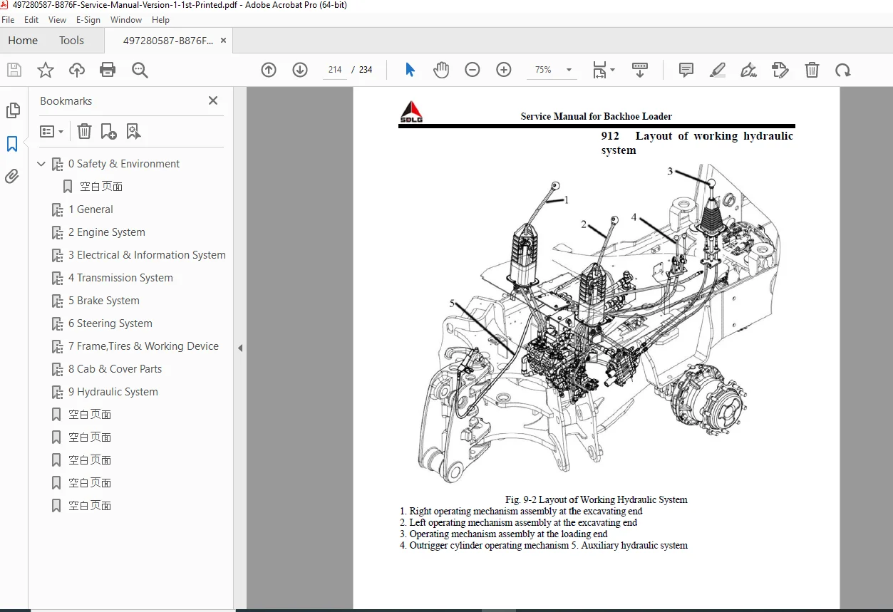
Hydraulic System at Loading End (92):
Layout and Schematic Diagrams:
- Complete hydraulic circuit diagram
- Component location identification
- Flow path illustrations
Loading Valve (923):
- Valve body construction
- Four-in-one cylinder slide valve link
- Boom slide valve link
- Main overflow valve
- Two-way overload fill valve
- Port connections:
- A1/B1: Four-in-one cylinder (small/big cavity)
- A2/B2: Scoop cylinder (big/small cavity)
- A3/B3: Boom cylinder (small/big cavity)
Working Pressure Measurement (924):
- Test equipment required:
- 40 MPa pressure gauge (part 40030000370)
- T-joint (part 41120001850)
- Test joint (part 40030000416)
- Test hose (part 40030000368)
- Oil temperature requirement: 45-55°C
- Pressure standard: 22.5 MPa
- Step-by-step testing procedures
- Safety pressure relief procedures
Hydraulic System at Excavating End (93):
- Excavation valve configuration
- Rotary control valve
- Pilot control system
- Pressure specifications for each function
- Complete circuit diagrams
Outrigger Hydraulic System (94):
- Outrigger cylinder control
- Valve operation
- Safety lockout features
Auxiliary Hydraulic System (95):
- Auxiliary attachment connections
- Flow and pressure specifications
- Quick coupler operation
Maintenance Attentions (96):
- Hydraulic oil specifications and change intervals
- Filter replacement schedules
- System cleanliness requirements
- Hose and fitting inspection
- Cylinder seal replacement
- Tank breather service
Fault Diagnosis and Troubleshooting (97):
- Slow operation diagnosis
- Weak digging force troubleshooting
- Erratic operation causes
- Oil temperature problems
- Contamination identification
- Pump failure diagnosis
- Valve malfunction troubleshooting
- Cylinder leakage identification
COMPREHENSIVE TECHNICAL DATA INCLUDED
Filling Capacities (Table 0-8):
- Fuel tank: 135 liters
- Hydraulic oil: 155 liters
- Engine oil: 10 liters
- Gearbox transmission oil: 20 liters
- Front axle (main drive + wheel reducers): 7.5 + 1.6 liters
- Rear axle: 15 liters
- Brake system: 2 liters
Operating Performance:
- Lifting time (full load): 3.36 seconds
- Lowering time (empty bucket): 1.77 seconds
- Unloading time (empty bucket): 1.44 seconds
- Total cycle time: 6.6 seconds
Standard Tightening Torques:
- Complete torque charts for bolt sizes 6mm through 39mm
- Multiple strength classes (4.6, 5.6, 6.8, 8.8, 10.9, 12.9)
- Torque ranges from 36 N·m to 5082 N·m
KEY TECHNICAL FEATURES
✓ Complete YC4A105Z-T20 engine specifications with 75 kW turbocharged diesel
✓ ZF transmission system with 4-speed power shift gearbox
✓ Load-sensing hydraulic steering system (15 MPa working pressure)
✓ Dual hydraulic systems for loading (22.5 MPa) and excavating (22.5/24 MPa)
✓ Vacuum boosting brake system with parking brake specifications
✓ Complete air conditioner service including R134a refrigerant procedures
✓ Detailed hydraulic pressure testing with specific tools and procedures
✓ Comprehensive safety guidelines for all operations and maintenance
✓ Environmental protection protocols for waste disposal and fluid handling
✓ Complete electrical system diagrams with I-ECU instrument panel details
✓ Torque specifications for all fasteners and assemblies
✓ Fault diagnosis flowcharts for all major systems
WHO NEEDS THIS MANUAL?
- Heavy Equipment Technicians servicing SDLG backhoe loaders
- Construction Fleet Maintenance Departments maintaining backhoe equipment
- SDLG Dealerships performing warranty and repair work
- Equipment Rental Companies servicing rental fleet loaders
- Municipal/Government Fleet Shops maintaining public works equipment
- Agricultural Mechanics working with farm construction equipment
- Technical Training Programs teaching backhoe loader maintenance
- Independent Heavy Equipment Repair Shops servicing SDLG machines
- Mining and Quarry Operations maintaining excavation equipment
- Utility Companies servicing trenching and excavation equipment
CRITICAL SYSTEMS COVERED
Power Train:
- Turbocharged diesel engine with direct injection
- ZF power shift transmission
- Torque converter with 2.529 ratio
- Drive axles with planetary reduction
- Four-wheel drive system
Hydraulic Systems:
- Load-sensing steering (priority valve system)
- Working hydraulics (loading, excavating, outrigger, auxiliary)
- Multi-way valve control
- Hydraulic cylinder service (7 different cylinders)
- Pressure testing and adjustment
Electrical Systems:
- 12V starting and charging
- I-ECU instrument cluster with digital display
- Complete alarm system (8 functions)
- Lighting circuits
- Glow plug system for cold starting
Safety Systems:
- Vacuum-boosted service brakes
- Parking brake with caliper disc
- Loading arm safety lever
- Operator presence systems
- Fire prevention protocols
Stop searching through incomplete online resources and unreliable information! This official SDLG factory service manual provides instant access to complete system specifications, detailed hydraulic circuit diagrams, step-by-step disassembly procedures, and professional troubleshooting protocols. Download now and service your B876F backhoe loader with the same technical documentation used by certified SDLG technicians and authorized dealerships worldwide. Get your equipment back in operation with confidence using factory-authorized repair procedures and precise specifications!