Sennebogen 825 + 830 Operating Instruction Manual 825.0.1309 – PDF DOWNLOAD
$28.95
Sennebogen 825 + 830 Operating Instruction Manual 825.0.1309 – PDF DOWNLOAD
Description
Sennebogen 825 + 830 Operating Instruction Manual 825.0.1309 – PDF DOWNLOAD
FILE DETAILS:
Sennebogen 825 + 830 Operating Instruction Manual 825.0.1309 – PDF DOWNLOAD
Language : English
Pages : 316
Downloadable : Yes
File Type : PDF
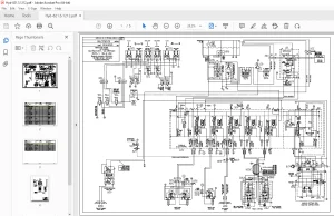
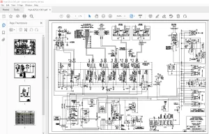
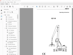
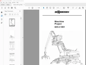
IMAGES PREVIEW OF THE MANUAL:
TABLE OF CONTENTS:
Sennebogen 825 + 830 Operating Instruction Manual 825.0.1309 – PDF DOWNLOAD
1 Safety 17
1 1 General 17
1 2 Intended use 18
1 3 Potential instances of misuse 19
1 4 Misuse 20
1 5 Other risks 20
1 6 Machine Labeling 21
1 6 1 Identification plate 21
1 6 2 CE stamp of conformity 22
1 6 3 Euro-test identification 22
1 6 4 Warning and notice labels 23
1 7 Responsibilities of the operator 28
1 8 Supplementary and operational equipment 34
1 8 1 SENNEBOGEN-Diagnostic-System (SDS) 34
1 8 2 Oils and lubricants 35
1 8 3 Coolant 36
1 8 4 Fuel (not with electric motors) 41
1 9 Safety instructions 42
1 9 1 General 42
1 9 2 Cleaning work 47
1 9 3 Safe entry and exit 48
1 9 4 Emergency exit 52
1 9 5 Emergency exit 52
1 9 6 Commissioning 53
1 9 7 Operation/Driving operation 54
1 9 8 Setup work 56
1 9 9 Decommissioning 57
1 9 10 Maintenance 58
1 9 11 Transportation 61
1 10 Safety devices 62
1 11 Disposal 63
1 12 Hand signals 64
2 Overview 69
2 1 Complete machine 69
2 1 1 Mobile 69
2 1 2 Crawler 70
2 1 3 Structure (4-point sub-frame) 71
2 1 4 Rails 72
2 2 Undercarriage 73
2 2 1 Mobile 73
2 2 2 Crawler 75
2 2 3 Structure (4-point sub-frame) 76
2 2 4 Rails 77
2 3 Superstructure 78
2 3 1 Side views with Diesel engine 78
2 3 2 Side views with electric motor 80
2 3 3 View from above 81
2 3 4 Central electrical system 82
2 3 5 Electrical control cabinet 83
2 4 Equipment 84
2 4 1 Compact boom 84
2 4 2 Pipe fracture safety devices 85
2 4 3 Attachments and Vario Tool (optional) 86
3 Customer-specific models and functions 87
3 1 Basic machine configuration 87
3 2 Lifting capacities 88
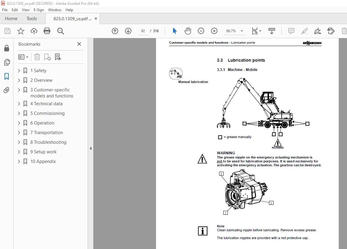
3 3 Lubrication points 92
3 3 1 Machine – Mobile 92
3 4 Warning and notice labels 94
3 5 Supplemental information 98
3 5 1 Driving speed (rails) 98
3 5 2 Machine dimensions (Rail / 4-point sub-frame) 98
3 5 3 Weight (Rail / 4-point sub-frame) 98
4 Technical data 99
4 1 General information 99
4 2 Driving engine 100
4 2 1 Type 825 101
4 2 2 Type 830 102
4 3 Machine 103
4 3 1 Mobile 103
4 3 2 Crawler 105
4 3 3 Structure 106
4 3 4 Rails 107
4 4 Machine dimensions 108
4 4 1 Mobile 108
4 4 2 Crawler 108
4 4 3 Structure (4-point sub-frame) 108
4 4 4 Rails 108
4 5 Machine weight 108
4 6 Wind speed 109
4 7 Conversion factors 110
5 Commissioning 111
5 1 Safety instructions 111
5 2 Cleaning work 111
5 3 Initial operation 113
5 4 Checks before daily start-up 113
5 5 Tests before start-up 118
5 5 1 Checking the windshield washer level 118
5 5 2 Check fuel level 119
5 5 3 Lubricating the lubrication points manually 120
5 5 4 Check fill level in central lubrication system 120
5 5 5 Check the quantity of grease on the slewing ring teeth 121
5 5 6 Checking the hydraulic oil level 123
5 5 7 Check and drain the fuel system 124
5 5 8 Checking engine oil level 126
5 5 9 Check coolant level 127
5 6 Check water heating coolant level (Optional) 128
5 7 Switch on machine – Diesel engine 130
5 7 1 Safety instructions 130
5 7 2 Restraint belt 131
5 7 3 Start engine 132
5 7 4 Bring machine up to operating temperature 134
5 7 5 Jump start 135
5 8 Switching the machine off – Diesel engine 136
5 8 1 Switching off engine 136
5 9 Decommissioning – Diesel engine 137
5 10 Preservation and storage – Diesel engine 138
5 11 Switch on machine – Electric motor 139
5 11 1 Safety instructions 139
5 11 2 Restraint belt 139
5 11 3 Start engine 141
5 11 4 Bring machine up to operating temperature 142
5 12 Switching the machine off – Electric motor 143
5 12 1 Switching the motor off 143
5 13 Decommissioning – Electric motor 144
5 14 Preservation and storage – Electric motor 145
5 15 Starting up operating again 146
5 16 Disposal 146
6 Operation 147
6 1 Safety instructions 147
6 2 Driver’s cab/cab with platform, raising 148
6 2 1 Driver’s seat 151
6 3 Operating elements 154
6 3 1 Overview with steering wheel control 154
6 3 2 Overview with joystick control 156
6 3 3 Overview with crawler steering 158
6 3 4 Safety lever 159
6 3 5 Control lever, left-hand 160
6 3 6 Control lever, right-hand 161
6 3 7 Additional displays 162
6 3 8 Overview of control panels 163
6 3 9 Control panel, next to the driver’s seat 164
6 3 10 Control panel Engine/Machine 166
6 3 11 Panel indicator lights, lower right 168
6 3 12 Control panel, right-hand bottom 170
6 3 13 Air conditioning control panel 173
6 3 14 Control panel, right bottom (rear) 175
6 3 15 Control panel, top right on the ceiling 177
6 3 16 SENNEBOGEN Diagnosis System (SDS) 183
6 4 Additional displays (special equipment) 205
6 4 1 SENNEBOGEN Tool Control 205
6 4 2 Load moment limiter (LML) 207
6 4 3 Generator and Magnet Systems 208
6 4 4 Camera/Monitor 209
6 4 5 Auxiliary heating / Water heater 210
6 4 6 Low-temperature package 212
6 4 7 External loudspeaker system 216
6 5 Application 217
6 5 1 Safety instructions 217
6 5 2 Maneuvering cab 218
6 5 3 Emergency lowering – cab 221
6 5 4 Driving machine – Mobile 223
6 5 5 Stabilizing machine – Mobile 226
6 5 6 Driving machine – Crawler 230
6 5 7 Changing the crawler track width (hydraulic – optional) 233
6 5 8 Changing crawler track width (mechanical) 236
6 5 9 Superstructure rotation/braking 239
6 5 10 Lifting /lowering loads 242
6 5 11 End limit cut-out equipment 243
6 5 12 Bypassing the safety limit position sensor for “Arm in” 247
6 5 13 Working with the grab 248
6 5 14 Operation with generator and magnet system (special function) 249
6 5 15 Working with scrap shears (special function) 252
6 5 16 Working with a hydraulic hammer (special function) 253
6 6 Vario Tool – Changing equipment 254
6 6 1 Coupling 254
6 6 2 Disconnecting 257
6 6 3 Cleaning 257
6 7 Refueling machine 260
6 8 Actions to take if the electronics fail 263
6 8 1 Reverse airflow -insufficient cooling capacity- 263
6 8 2 Steering failure (optional with joystick steering) 264
6 9 Towing 265
7 Transportation 269
7 1 Safety instructions 269
7 2 Machine dimensions 270
7 2 1 Mobile 270
7 2 2 Crawler 272
7 2 3 Structure (4-point sub-frame) 273
7 2 4 Rails 273
7 3 Machine weight 273
7 4 Lock upper structure 274
7 5 Lifting machine 275
7 6 Tie down machine 277
7 7 Disconnect electrical system from battery 278
8 Troubleshooting 279
8 1 Driving engine 279
8 2 Hydraulic system: 280
8 3 Heater 282
8 4 tires and undercarriage 283
8 5 Cab 283
8 6 SDS fault indicators 284
9 Setup work 289
9 1 Safety instructions 289
9 2 Dismantling/assembling the cab 291
9 3 Mounting/dismounting counterweight 292
9 3 1 Dismantling the counterweight 293
9 3 2 Installing the counterweight 294
9 4 Installing large roller bearings, slewing gear, flange connections 295
9 4 1 General 295
9 4 2 Preparatory measures 295
9 4 3 Assembly 296
9 4 4 Mounting pylon 298
9 5 Quick-change couplings 299
9 5 1 Fastening quick couplings 299
9 5 2 Pull out coupling insert 302
9 5 3 Check/change sealing ring 303
9 5 4 Lubricating the coupling sleeve 305
10 Appendix 307
10 1 List of abbreviations 307
10 2 Index 308
10 3 Driver’s seat 308
10 4 Clean the cooling system 308
10 5 Quick-connect couplings 308
10 6 Installing large roller bearings, slewing gear, flange connections 308
10 7 Warranty conditions 308
10 8 Electrical water heater 308
10 9 Lubricants table 308
S.V 05/24