
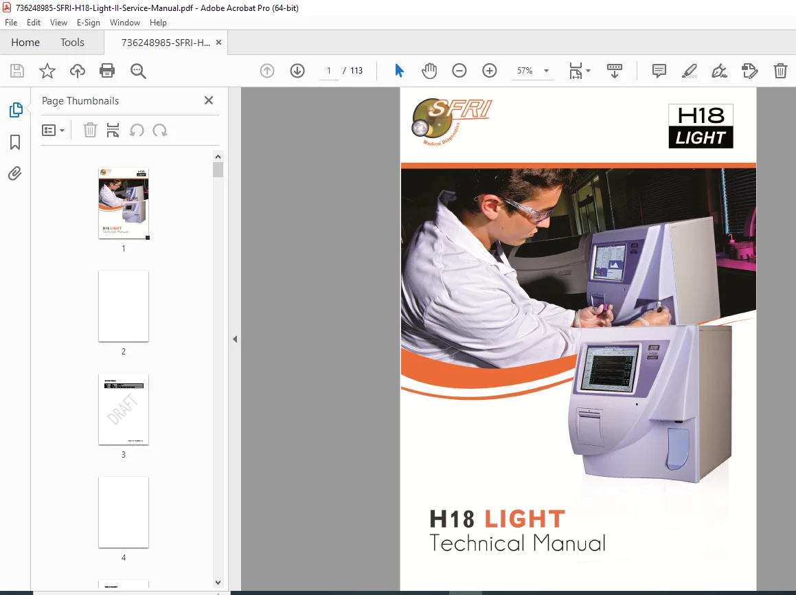
SFRI H18 Light V2 Technical Service Manual (Hematology Analyzer) – PDF
Original price was: $75.00.$15.95Current price is: $15.95.
This is the official technical service manual for the SFRI H18 Light V2 3-part differential hematology analyzer. It includes complete mechanical, fluidic, and electronic repair procedures, along with CCU/CPU board documentation. The manual provides a full troubleshooting guide, all technician-level service passwords, and the official SFRI preventive maintenance workflow. Essential for biomedical engineers servicing the H18 Light.
Description
SFRI H18 Light V2 Technical Service Manual (Hematology Analyzer) – PDF DOWNLOAD
Description
This is the complete official service manual for the SFRI H18 Light V2 hematology analyzer. Written for biomedical service engineers, it provides full installation, configuration, calibration, troubleshooting, and repair instructions for this compact 3-part differential analyzer.
The manual covers the complete inner workings of the instrument, including Coulter principle cell counting, photometric hemoglobin measurement, fluidics logic, motor sequences, electronic boards, sensors, and service-level software functions. It also includes all preventive maintenance procedures and complete technician passwords.
📑 TABLE OF CONTENTS
1. Specifications
Front and rear panel diagrams
List of 20 analytical parameters + 3 histograms
Sample volumes, dilution ratios, lyse volumes
Linearity, precision, and performance ranges
2. Installation Procedure
Site requirements (space, ventilation, electrical supply)
Unpacking and instrument verification
Start-up and self-check sequence
Background check
Stability / CV verification
Calibration procedures
3. Theory of Operation
Cell counting using the Coulter Principle
RBC and WBC aperture measurement
Hemoglobin reading using spectrophotometry
Overview of the analog + digital signal chain
4. Fluidics System
Fluidics cycle (Standby → Dilution → Counting → Cleaning)
Complete fluidic algorithm and flow schematic
RBC chamber, WBC chamber, and dilution block operation
Vacuum block, valves, pumps, sensors
Fluidic timing, thresholds, and step-by-step diagrams
5. Electronics
Switching Power Supply (S020056-V2)
Voltage map, connectors, protections.
CCU Board (Central Command Unit)
Full schematic and component layout
Connectors, pin assignments, peripherals
Signal flow and main functions
CPU Board (Central Processing Unit)
Processor functions
EEPROM and firmware roles
Communication and data paths
Liquid Sensor Adj./Distribution Board
LCD Adaptor Board / Thermal Printer Driver Board
6. Mechanics
Sample probe arm assembly
Motor A & Motor B control
Dilution machine (Motor C)
Vacuum pump assembly (Motor D)
Mechanical movement tests and alignment
7. Service Software
Mechanic Mode (Password: 6100)
Test motors, electronic valves, sensors, load circuits.
Special – Factory Mode (Password: 6666)
Factory calibration, CV checks, advanced diagnostic access.
Special – Parameters Adjust (Password: 6161)
Motor steps, fluidic timing, aspiration volume adjustments.
Network Transfer Protocol
RS-232 data output format.
8. Adjustments and Controls
HGB Blank Voltage Adjustment (Target: 4.31 V ± 0.2 V)
Vacuum Accuracy Check (Target: 236 mbar)
Aperture Voltage Checks
WBC: 9–19 V
RBC: 11–25 V
Reagent sensor sensitivity adjustment
Motor step calibration
9. Maintenance
User Maintenance
Daily: cleaning cycles, reagent checks
Weekly: tubing cleaning, background verification
Monthly: drain cleaning, fluidic block inspection
Technical Preventive Maintenance (SFRI PMK0201)
Replacing vacuum pump seals
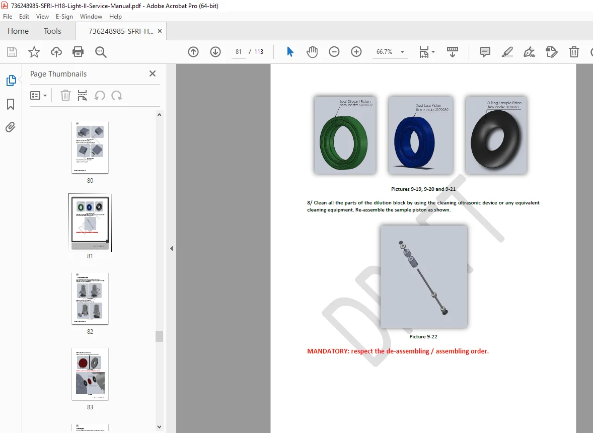
Replacing dilution block seals
Motor lubrication and tightening
Fluidics cleaning and aperture conditioning
10. Troubleshooting
Complete troubleshooting table covering all common faults:
HGB Bubble
HGB Lamp Failure
RBC CLOG
WBC CLOG
Motor A/B/C/D Stop Busy
Reagent Empty / Sensor Fault
Abnormal background
Vacuum instability
Printer and LCD failures
Appendices
Appendix 3: Technician Passwords
Appendix 4: Fluidic Cycle Step-by-Step (Illustrated)
Appendix 6: Spare Parts List
Includes probes, valves, vacuum pump, dilution block, sensors, boards, and mechanical assemblies.
5. File Details
| Detail | Information |
|---|---|
| Manual Name | H18 LIGHT Technical Manual |
| Models Covered | H18 Light V2 (Serial numbers > 02010411) |
| Version / Year | V13.00 — 09/12/2013 |
| Manual PDF Quality | High-quality digital “DRAFT” version (searchable text, clear schematics) |
| Page Count | 113 pages |