Skyjack SJ 6826RT SJ 6832RT Compact Rough Terrain Series Parts Manual 143898AD – PDF DOWNLOAD
$27.95
Skyjack SJ 6826RT SJ 6832RT Compact Rough Terrain Series Parts Manual 143898AD – PDF DOWNLOAD
SJ 68XXRT 37,002,164 to 37,002,787
Description
Skyjack SJ 6826RT SJ 6832RT Compact Rough Terrain Series Parts Manual 143898AD – PDF DOWNLOAD
FILE DETAILS:
Skyjack SJ 6826RT SJ 6832RT Compact Rough Terrain Series Parts Manual 143898AD – PDF DOWNLOAD
Language : English
Pages : 148
Downloadable : Yes
File Type : PDF
DESCRIPTION:
Skyjack SJ 6826RT SJ 6832RT Compact Rough Terrain Series Parts Manual 143898AD – PDF DOWNLOAD
SJ 68XXRT 37,002,164 to 37,002,787
The information contained in this section is designed to aid the user in locating and identifying
replacement parts. Component parts of various assemblies and sub-assemblies comprising the
work platform are illustrated and accompanied by a descriptive parts list. Exploded drawings are
used to show relative location of component parts in disassembly order. If a part cannot be found
in this section, order by work platform model number and serial number, giving a complete
description of the part.
When ordering replacement parts, the complete part number and description should be used to
ensure proper identification and delivery of the desired item. This complete identification should
also be used when requesting equipment information.
followed by a full description based upon the “NOUN FIRST” method. That is, the noun name
of the part is listed first, then the modifying description information which serves to
specifically identify the item. For example: PIN, Clevis. Assemblies or groups are shown at the
beginning of a parts list and are identified with the letter references A, B, C, etc. Individual
parts in these lists have corresponding letters after their description to identify which assembly
or group it is used in. Individual parts without identifying letters are used in all the assemblies
or group shown at the beginning of the parts list. Descriptions preceded with an (•) indicates
a serviceable component or attaching hardware for the higher level assembly. If
an index number initially starts with the letter “K”, for
example “K1”, means it’s a kit. Any item(s) included
in a kit will not have an index number.
complete the assembly. If quantity is (AR), it is understood that the quantity may vary when
machine is equipped with certain options. Order quantity as needed.
Standard screws, washers, nuts, etc. are not identified by a reference number. These parts
are known as COMMON HARDWARE items and appear indented under the major items with which they are
used. They should be ordered separately as listed, since they are not component parts of the pieces
they attach to.
1. Address all orders to your local SKYJACK dealer.
2. Specify model and serial number of the work
platform (found on the serial number plate).
3. List the quantity needed.
4. List the length needed (if bulk item).
5. List the part number and description as shown in this manual for each item.
6. Show billing and shipping address and name of individual if possible.
7. Suggest best routing.
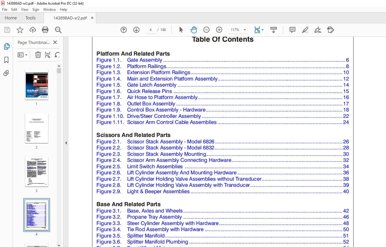
TABLE OF CONTENTS:
Skyjack SJ 6826RT SJ 6832RT Compact Rough Terrain Series Parts Manual 143898AD – PDF DOWNLOAD
Platform And Related Parts
Figure 1 1 Gate Assembly 6
Figure 1 2 Platform Railings 8
Figure 1 3 Extension Platform Railings 10
Figure 1 4 Main and Extension Platform Assembly 12
Figure 1 5 Gate Latch Assembly 14
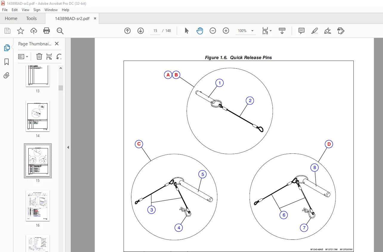
Figure 1 6 Quick Release Pins 15
Figure 1 7 Air Hose to Platform Assembly 16
Figure 1 8 Outlet Box Assembly 17
Figure 1 9 Control Box Assembly – Hardware 18
Figure 1 10 Drive/Steer Controller Assembly 22
Figure 1 11 Scissor Arm Control Cable Assemblies 24
Scissors And Related Parts
Figure 2 1 Scissor Stack Assembly – Model 6826 26
Figure 2 2 Scissor Stack Assembly – Model 6832 28
Figure 2 3 Scissor Stack Assembly Mounting 30
Figure 2 4 Scissor Arm Assembly Connecting Hardware 32
Figure 2 5 Limit Switch Assemblies 34
Figure 2 6 Lift Cylinder Assembly And Mounting Hardware 36
Figure 2 7 Lift Cylinder Holding Valve Assemblies without Transducer 38
Figure 2 8 Lift Cylinder Holding Valve Assembly with Transducer 39
Figure 2 9 Light & Beeper Assemblies 40
Base And Related Parts
Figure 3 1 Base, Axles and Wheels 42
Figure 3 2 Propane Tray Assembly 46
Figure 3 3 Steer Cylinder Assembly with Hardware 48
Figure 3 4 Tie Rod Assembly with Hardware 50
Figure 3 5 Splitter Manifold 51
Figure 3 6 Splitter Manifold Plumbing 52
Figure 3 7 Front Wheel Motor 54
Figure 3 8 Rear Wheel Motor 56
Figure 3 9 Main Manifold Plumbing 58
Figure 3 10 Hydraulic Cabinet Assembly 60
Figure 3 11 Oil Tank Assembly 62
Figure 3 12 Gas Tank Assembly 63
Figure 3 13 Main Manifold 64
Figure 3 14 Hydraulic Door Assembly 68
Figure 3 15 Engine Cabinet Assembly 70
Figure 3 16 Electrical Panel Assembly 72
Figure 3 17 Engine Installation (Kubota DF972) 74
Figure 3 18 Engine Installation (Kubota D902) 76
Figure 3 19 Tray Engine Assembly 78
Figure 3 20 Engine Door Assembly 79
Figure 3 21 Engine and Main Manifold Harness Diagrams 80
Figure 3 22 Electrical Panel Harness Diagram 82
Figure 3 23 Load Sensing Components 84
SJRT Compact Series Page 5
143898
Table Of Contents
Engines And Related Parts
Figure 4 1 Engine Assembly (Kubota Engine DF972) 86
Figure 4 2 Air Cleaner Assembly – Kubota Dual Fuel Engine DF972 92
Figure 4 3 Exhaust System Assembly – Kubota Engines DF972 / D902 93
Figure 4 4 Radiator Kit – Kubota DF972 / D902 94
Figure 4 5 Hydraulic Pump Assembly (Kubota Engine DF972 / D902) 96
Figure 4 6 Propane Fuel System – Kubota Dual Fuel Engine DF972 98
Figure 4 7 Propane Fuel System – Dual Tank (Kubota Engine DF972) 100
Figure 4 8 Engine Assembly (Kubota Engine D902) 102
Figure 4 9 Air Cleaner Assembly (Kubota Engine D902) 106
Figure 4 10 Hose Assembly, Fuel (Kubota D902) 107
Optional Equipment
Figure 5 1 Outrigger Control Box Assembly 108
Figure 5 2 Outrigger Electrical Connections 110
Figure 5 3 Front And Rear Outrigger Assembly 114
Figure 5 4 Outrigger Assembly 116
Figure 5 5 Outrigger Cylinder Assembly 118
Figure 5 6 Outrigger Hydraulic Connections 119
Figure 5 7 Outrigger Manifold Assembly 120
Figure 5 8 800W Inverter Option 122
Figure 5 9 110/220 Clamp Assembly Option 124
Figure 5 10 Hydraulic Generator Option 126
Figure 5 11 Hydraulic Hose Connection – Hydraulic Generator Option 128
Figure 5 12 Hydraulic Generator Relay Assembly 130
Figure 5 13 Scissor Guard Option With Diesel Fuel 132
Figure 5 14 Scissor Guard With Dual Fuel 134
Figure 5 15 Work Light Option 136
Labels And Nameplate
Figure 6 1 Label Kit 137
Figure 6 2 Labels – Chassis (Left and Back) 138
Figure 6 3 Labels – Chassis (Front and Right) 140
Figure 6 4 Labels – Chassis (Top) 141
Figure 6 5 Labels – Misc 142
Figure 6 6 Labels – Misc 144
Table 1 1 SJRT Scissor Fluids 146
IMAGES PREVIEW OF THE MANUAL:
Customer Support: [email protected]
PLEASE NOTE:
- This is not a physical manual but a digital manual – meaning no physical copy will be couriered to you. The manual can be yours in the next 2 mins as once you make the payment, you will be directed to the download page IMMEDIATELY.
- This is the same manual used by the dealers inorder to diagnose your vehicle of its faults.
- Require some other service manual or have any queries: please WRITE to us at [email protected]
S.V