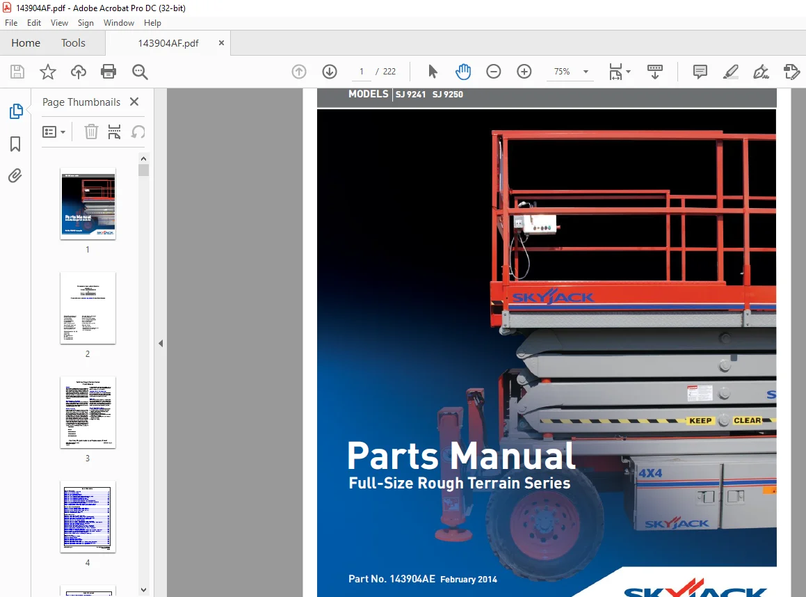
Skyjack SJ 9241 SJ 9250 Full-Size Rough Terrain Series Parts Manual 143904AE – PDF DOWNLOAD
$27.95
Skyjack SJ 9241 SJ 9250 Full-Size Rough Terrain Series Parts Manual 143904AE – PDF DOWNLOAD
Serial Numbers:
ANSI/CSA & AS
SJ 9250 50,000,513 TO 50,000,745
CE
SJ 9241 55,000,001 TO 55,000,032
SJ 9250 50,000,513 TO 50,000,745
Description
Skyjack SJ 9241 SJ 9250 Full-Size Rough Terrain Series Parts Manual 143904AE – PDF DOWNLOAD
FILE DETAILS:
Skyjack SJ 9241 SJ 9250 Full-Size Rough Terrain Series Parts Manual 143904AE – PDF DOWNLOAD
Language : English
Pages :222
Downloadable : Yes
File Type : PDF
DESCRIPTION:
Skyjack SJ 9241 SJ 9250 Full-Size Rough Terrain Series Parts Manual 143904AE – PDF DOWNLOAD
Serial Numbers:
ANSI/CSA & AS
SJ 9250 50,000,513 TO 50,000,745
CE
SJ 9241 55,000,001 TO 55,000,032
SJ 9250 50,000,513 TO 50,000,745
General
The information contained in this section is designed to aid the user in locating and identifying replacement parts. Component parts of various assemblies and subassemblies comprising the work platform are illustrated and accompanied by a descriptive parts list. Exploded drawings are used to show relative location of component parts in disassembly order. If a part cannot be found in this section, order by work platform model number and serial number, giving a complete description of the part.
Parts Ordering Information
When ordering replacement parts, the complete part number and description should be used to ensure proper identification and delivery of the desired item. This complete identification should also be used when requesting equipment information
Method Of Listing
- Parts are listed in order according to the reference number shown in the illustration, followed by a full description based upon the “NOUN FIRST” method. That is, the noun name of the part is listed first, then the modifying description information which serves to specifically identify the item. For example: PIN, Clevis. Assemblies or groups are shown at the beginning of a parts list and are identified with the letter references A, B, C, etc. Individual parts in these lists have corresponding letters after their description to identify which assembly or group it is used in. Individual parts without identifying letters are used in all the assemblies or group shown at the beginning of the parts list. Descriptions preceded with an (•) indicates a serviceable component or attaching hardware for the higher level assembly.
- If an index number initially starts with the letter “K”, for example “K1”, means it’s a kit. Any item(s) included in a kit will not have an index number.
IMAGES PREVIEW OF THE MANUAL:
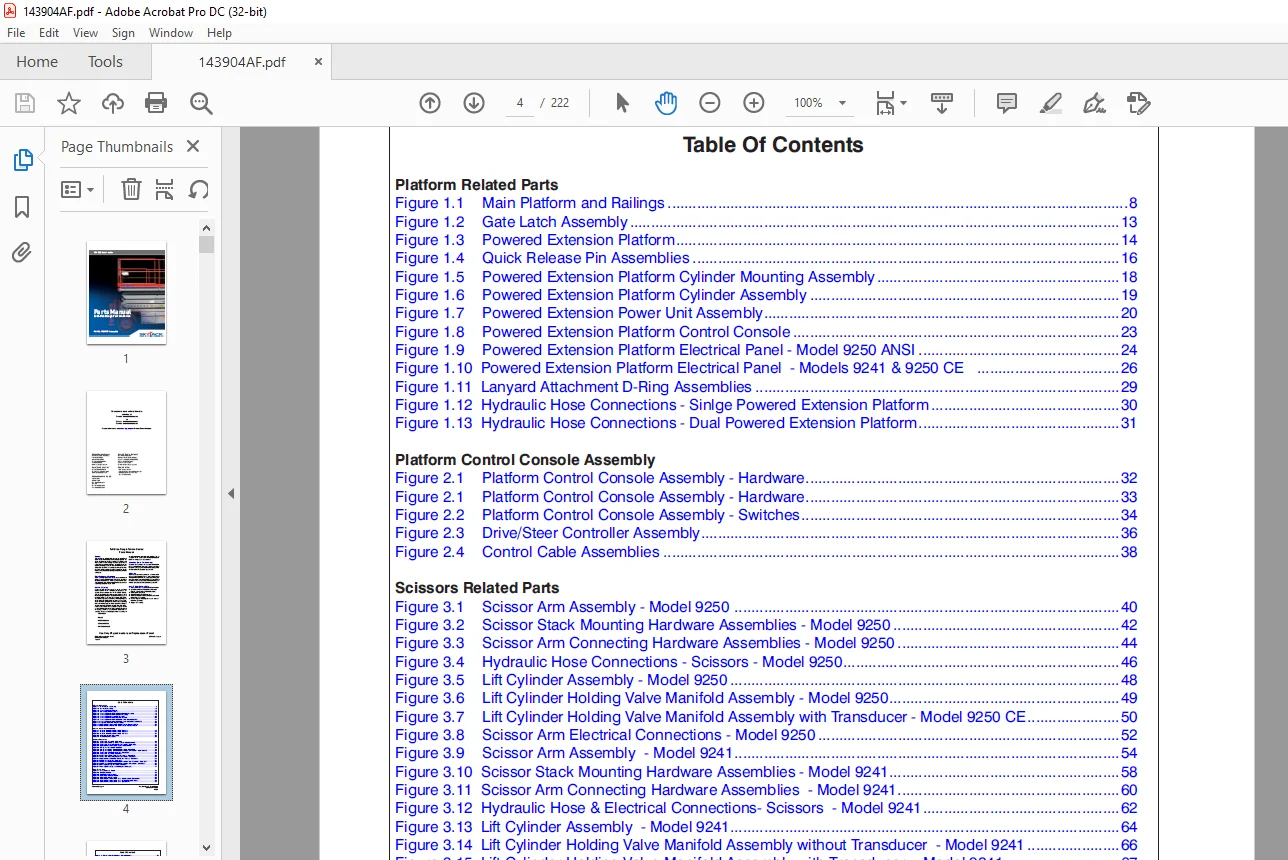
TABLE OF CONTENTS:
Skyjack SJ 9241 SJ 9250 Full-Size Rough Terrain Series Parts Manual 143904AE – PDF DOWNLOAD
Table of Contents 4
1 0 – Platform Related Parts 8
Figure 1 1 Main Platform and Railings 8
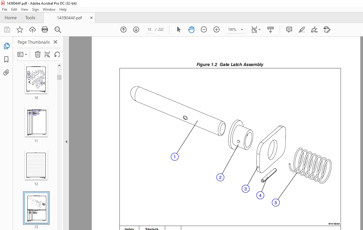
Figure 1 2 Gate Latch Assembly 13
Figure 1 3 Powered Extension Platform 14
Figure 1 4 Quick Release Pin Assemblies 16
Figure 1 5 Powered Extension Platform Cylinder Mounting Assembly 18
Figure 1 6 Powered Extension Platform Cylinder Assembly 19
Figure 1 7 Powered Extension Power Unit Assembly 20
Figure 1 8 Powered Extension Platform Control Console 23
Figure 1 9 Powered Extension Platform Electrical Panel – Model 9250 ANSI 24
Figure 1 10 Powered Extension Platform Electrical Panel – Models 9241 & 9250 CE 26
Figure 1 11 Lanyard Attachment D-Ring Assemblies 29
Figure 1 12 Hydraulic Hose Connections – Sinlge Powered Extension Platform 30
Figure 1 13 Hydraulic Hose Connections – Dual Powered Extension Platform 31
2 0 – Platform Related Parts 32
Figure 2 1 Platform Control Console Assembly – Hardware 32
Figure 2 2 Platform Control Console Assembly – Switches 34
Figure 2 3 Drive/Steer Controller Assembly 36
Figure 2 4 Control Cable Assemblies 38
3 0 – Scissor Related Parts 40
Figure 3 1 Scissor Arm Assembly – Model 9250 40
Figure 3 2 Scissor Stack Mounting Hardware Assemblies – Model 9250 42
Figure 3 3 Scissor Arm Connecting Hardware Assemblies – Model 9250 44
Figure 3 4 Hydraulic Hose Connections – Scissors – Model 9250 46
Figure 3 5 Lift Cylinder Assembly – Model 9250 48
Figure 3 6 Lift Cylinder Holding Valve Manifold Assembly – Model 9250 49
Figure 3 7 Lift Cylinder Holding Valve Manifold Assembly with Transducer – Model 9250 CE 50
Figure 3 8 Scissor Arm Electrical Connections – Model 9250 52
Figure 3 9 Scissor Arm Assembly – Model 9241 54
Figure 3 10 Scissor Stack Mounting Hardware Assemblies – Model 9241 58
Figure 3 11 Scissor Arm Connecting Hardware Assemblies – Model 9241 60
Figure 3 12 Hydraulic Hose & Electrical Connections- Scissors – Model 9241 62
Figure 3 13 Lift Cylinder Assembly – Model 9241 64
Figure 3 14 Lift Cylinder Holding Valve Manifold Assembly without Transducer – Model 9241 66
Figure 3 15 Lift Cylinder Holding Valve Manifold Assembly with Transducer – Model 9241 67
Figure 3 16 Horn, Light & Beeper Assembly (ANSI/CSA) 68
Figure 3 17 Horn, Light, Beeper, & Load Sensing Assemblies (CE) 71
4 0 – Base Related Parts 72
Figure 4 1 Base, Axles, and Wheels 72
Figure 4 2 Fuel Side Cabinet 76
Figure 4 3 Fuel Tank and Connections 79
Figure 4 4 Hydraulic/Electric Side Cabinet 80
Figure 4 5 Hydraulic Oil Tank Assembly 86
Figure 4 6 Hydraulic Hose Connections – Base (Cushman Axles) (Model 9250) 88
Figure 4 7 Hydraulic Hose Connections – Base (Dana Axles) (Model 9250) 90
Figure 4 8 Hydraulic Hose Connections – Base (Model 9241) 92
Figure 4 9 Hydraulic Hose Connections – Hydraulic Cabinet 94
Figure 4 10 Cushion Valve Assembly 96
Figure 4 11 Emergency Lowering Valve Assembly 97
Figure 4 12 Emergency Lowering Wiring Assembly (Model 9250 ANSI/CSA) 98
Figure 4 13 Emergency Lowering and Power Platform Retraction Wiring Assembly (Model 9250 CE) 100
Figure 4 14 Brake Cylinder Assembly (Model 9250) 102
Figure 4 15 Motion Control Valve Assembly 103
Figure 4 16 Auto Reset Brake Manifold Assembly (Cushman Axles) 104
Figure 4 17 Main Manifold Assembly 106
Figure 4 18 Base Control / Electrical Panel Assembly 108
Figure 4 19 Base Control/Electrical Panel Harnesses 112
Figure 4 20 Base Control Console 114
5 0 – Axle Related Parts 116
Figure 5 1 Front Idle Arm Assembly – 2-Wheel Drive Machines 116
Figure 5 2 Front Axle Hardware Assembly – All Wheel Drive Option (Cushman Axles) 118
Figure 5 3 Front Axle Assembly – All Wheel Drive Option (Cushman Axles) 120
Figure 5 4 Front Axle Assembly (Axle End) – All Wheel Drive Option (Cushman Axles) 122
Figure 5 5 Front Axle (Differential Assembly) – All Wheel Drive Option (Cushman Axles) 124
Figure 5 6 Front & Rear Axle (Wheel Hub Assembly) – All Wheel Drive Option (Cushman Axles) 126
Figure 5 7 Front Axle (Axle Shaft Assembly) – All Wheel Drive Option (Cushman Axles) 127
Figure 5 8 Steer Cylinder Assembly (Cushman Axles) 128
Figure 5-9 Front Axle Assembly (For 4-wheel Drive Machines) (Dana Axles) 130
Figure 5 10 Front Drive Axle Assembly – Four Wheel Drive Machines (Dana Axles) 132
Figure 5 11 Steer Cylinder Assembly (Dana Axles) 136
Figure 5 12 Drive Shaft Assembly 138
Figure 5 13 Drive Motor Assembly 141
Figure 5 14 Center Drive Assembly 142
Figure 5 15 Rear Axle Assembly – (Cushman Axles) 144
Figure 5 16 Rear Axle (Differential Assembly) – (Cushman Axles) 146
Figure 5 17 Rear Axle (Brake Assembly) – (Cushman Axles) 148
Figure 5 18 Rear Drive Axle Assembly (Dana Axles) 150
6 0 – Engine Related Parts 152
Figure 6 1 Engine Roll Out Tray & Cover Assembly 152
Figure 6 2 Engine Control Panel 156
Figure 6 3 Diesel Engine Assembly (Kubota Diesel Engine D1305) 158
Figure 6 4 Diesel Fuel System (Kubota Diesel Engine D1305) 164
Figure 6 5 Kubota Diesel Fuel Engine Harness 166
Figure 6 6 Air Intake Assembly (Kubota Diesel Engine D1305) 168
Figure 6 7 Hydraulic Pump Assembly 169
Figure 6 8 Exhaust Manifold Assembly (Kubota Diesel Engine D1305) 170
Figure 6 9 Engine Roll Out Accessories (GM Dual Fuel Engine) 172
Figure 6 10 Dual Fuel Engine Assembly (GM Dual Fuel Engine) 174
Figure 6 11 Bell Housing Assembly (GM Dual Fuel Engine) 180
Figure 6 12 Engine Interface Harness (GM Dual Fuel Engine) 182
Figure 6 13 Dual Fuel Hose Assembly (GM Dual Fuel Engine) 184
7 0 – Optional Equipment 186
Figure 7 1 Hydraulic Outrigger – Electrical Panel Connections 186
Figure 7 2 Hydraulic Outrigger Option – Hydraulic Hose Connection 188
Figure 7 3 Hydraulic Outrigger Option – Leg Assembly 190
Figure 7 4 Hydraulic Outrigger Option – Cylinder Assembly 192
Figure 7 5 Hydraulic Outrigger Option – Manifold Assembly 193
Figure 7 6 Outrigger/Hydraulic Generator Control Console Assembly 194
Figure 7 7 3500W Hydraulic Generator Option – Generator, Oil Cooler & Mounting 196
Figure 7 8 3500W Hydraulic Generator Option – Hydraulic Hose Connections 198
Figure 7 9 1500W Inverter Option 200
Figure 7 10 Scissor Guard 202
Figure 7 11 Work Light Option 204
Figure 7 12 Air Hose to Platform Option 205
Figure 7 13 Load Sensing Components (CE) 206
Figure 7 14 Platform AC Outlet Assembly 208
8 0 – Labels 209
Figure 8 1 Label Kit 209
Figure 8 2 Labels and Nameplate – Control Console Assemblies 210
Figure 8 3 Labels and Nameplate – Misc 212
Figure 8 4 Labels and Nameplate – Chassis 214
Figure 8 5 Labels – Outrigger 216
9 0 – Fluid Tables 218
Table 1 1 SJRT Scissor Fluids 218
Contact us: [email protected]
PLEASE NOTE:
- This is the SAME exact manual used by your dealers to fix your vehicle.
- The same can be yours in the next 2-3 mins as you will be directed to the download page immediately after paying for the manual.
- Any queries / doubts regarding your purchase, please feel free to contact [email protected]
S.M