Skyjack SJ46AJ SJ51AJ Articulating Booms Service Manual 143921AH – PDF DOWNLOAD
$28.95
Skyjack SJ46AJ SJ51AJ Articulating Booms Service Manual 143921AH – PDF DOWNLOAD
Description
Skyjack SJ46AJ SJ51AJ Articulating Booms Service Manual 143921AH – PDF DOWNLOAD
FILE DETAILS:
Skyjack SJ46AJ SJ51AJ Articulating Booms Service Manual 143921AH – PDF DOWNLOAD
Language : English
Pages : 192
Downloadable : Yes
File Type : PDF
IMAGES PREVIEW OF THE MANUAL:
DESCRIPTION:
Skyjack SJ46AJ SJ51AJ Articulating Booms Service Manual 143921AH – PDF DOWNLOAD
SJ46AJ & SJ51AJ 95 000 001 to 95 000 656
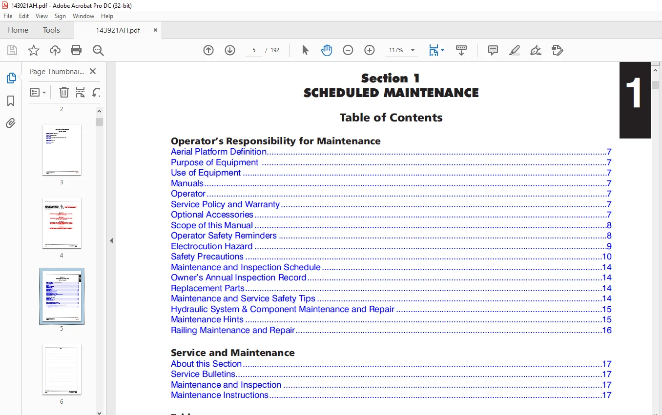
Scheduled Maintenance Operator’s Responsibility for Maintenance;
SKYJACK is continuously improving and expanding product features on its equipment, therefore, specifications
and dimensions are subject to change without notice.
Aerial Platform and Mobile Elevating Work Platform (MEWP) Definition
A mobile device that has a positionable platform supported from ground level by a structure.
Purpose of Equipment
The SKYJACK Veritcal Mast series aerial platform are designed to transport and raise personnel, tools and materials
to overhead work areas.
Use of Equipment
The aerial platform is a highly maneuverable, mobile work station. Lifting and driving must be on a flat, level,
compacted surface. It can be driven over uneven terrain only when the platform is fully lowered.
Manuals:
Operating:
The operating manual is considered a fundamental part of the aerial platform. It is a very important way to
communicate necessary safety information to users and operators. A complete and legible copy of this manual
must be kept in the provided weather-resistant storage compartment on the aerial platform at all times.
Service & Maintenance:
The purpose of this is to provide the customer with the servicing and maintenance procedures essential for
the promotion of proper machine operation for its intended purpose.
All information in this manual should be read and understood before any attempt is made to service the machine.
Operator:
The operator must read and completely understand both this operating manual and the safety panel label located
on the platform and all other warnings in this manual and on the aerial platform. Compare the labels on the aerial
platform with the labels found within this manual. If any labels are damaged or missing, replace them immediately.
TABLE OF CONTENTS:
Skyjack SJ46AJ SJ51AJ Articulating Booms Service Manual 143921AH – PDF DOWNLOAD
Cover.......................................................................................  1
Table of Contents...........................................................................  3
Section 1 - Scheduled Maintenance...........................................................  5
	Operator’s Responsibility for Maintenance...............................................  7
		Aerial Platform Definition..........................................................  7
		Purpose of Equipment ...............................................................  7
		Use of Equipment....................................................................  7
		Manuals.............................................................................  7
		Operator............................................................................  7
		Service Policy and Warranty.........................................................  7
		Optional Accessories................................................................  7
		Scope of this Manual................................................................  8
		Operator Safety Reminders...........................................................  8
		Electrocution Hazard................................................................  9
		Safety Precautions.................................................................. 10
		Maintenance and Inspection Schedule................................................. 14
		Owner’s Annual Inspection Record.................................................... 14
		Replacement Parts................................................................... 14
		Maintenance and Service Safety Tips................................................. 14
		Hydraulic System & Component Maintenance and Repair................................. 15
		Maintenance Hints................................................................... 15
		Railing Maintenance and Repair...................................................... 16
	Service and Maintenance................................................................. 17
		About this Section.................................................................. 17
		Service Bulletins................................................................... 17
		Maintenance and Inspection.......................................................... 17
		Maintenance Instructions............................................................ 17
	Tables.................................................................................. 18
		Table 1.1  Owner’s Annual Inspection Record......................................... 18
		Table 1.2  Maintenance and Inspection Checklist..................................... 19
	Scheduled Maintenance Inspections and Function Tests.................................... 20
		1.1 Scheduled Maintenance Inspections............................................... 20
		1.2 Function Tests.................................................................. 28
Section 2 - Maintenance Tables and Diagrams................................................. 41
	Tables.................................................................................. 42
		Table 2.1  Standard Hose Numbering System........................................... 42
		Table 2.2  Aerial Platform Torque Specifications.................................... 44
		Table 2.3  Axles Torque Specifications.............................................. 45
		Table 2.4  Axles Maintenance Intervals.............................................. 46
		Table 2.5  Tire Specifications...................................................... 47
		Table 2.6 Maximum Platform Capacities............................................... 47
		Table 2.7  Floor Loading Pressure................................................... 48
		Table 2.8  Hydraulic Specifications................................................. 49
		Table 2.9  Specifications and Features.............................................. 50
	Diagrams................................................................................ 52
		Diagram 2.1  Dimension and Reach Diagram - SJ 46A................................... 52
		Diagram 2.2  Dimension and Reach Diagram - SJ 46AJ.................................. 53
		Diagram 2.3  Dimension and Reach Diagram - SJ 51AJ.................................. 54
		Diagram 2.4  Axle Oscillation Diagram............................................... 55
Section 3 - System Component Identification and Schematics.................................. 57
	Charts.................................................................................. 58
		3.1  Hydraulic Symbol Chart......................................................... 58
		3.2  Electrical Symbol Chart........................................................ 59
		3.3  Wire Number and Color Code..................................................... 60
	Parts Lists............................................................................. 61
		3.4  Hydraulic Schematic Parts List ................................................ 61
		3.5  Electrical Component Parts List................................................ 64
	Diagrams and Schematics................................................................. 67
		3.6  Rotary Manifold and Port Identifications....................................... 67
		3.8  Drive and System Pump and Port Identifications................................. 68
		3.9  Drive Motors and Port Identifications.......................................... 69
		3.10  Jib Valves and Port Identifications........................................... 70
		3.11a  Main Manifold and Port Identifications....................................... 71
		3.11b  Main Manifold and Electrical Identifications................................. 72
		3.11c  Main Manifold and Hydraulic Identifications.................................. 73
		3.12  Main Electrical Harness  and Fuel Level Switch Harness........................ 74
		3.13  ECU Engine Wiring Diagram (Deutz Diesel Engine)............................... 75
		3.15  Engine Interface Harness (GM Dual Fuel Engine)................................ 76
		3.16  Harnesses..................................................................... 77
		3.17  Platform Control Cable Harnesses.............................................. 78
		3.18  Limit Switch Connections at Base Control Console.............................. 79
		3.19  Load Sensing Cable Connection (CE & AS)....................................... 80
		3.20  Hydraulic Schematic Diagram................................................... 81
		3.22  Platform Control Console Diagram (CE, SJ 46AJ/51AJ - Deutz Diesel Engine)..... 83
		3.23  Platform Control Console Diagram (AS, SJ46AJ/51AJ - Deutz Diesel Engine)...... 84
		3.24  Platform Control Console Diagram (ANSI/CSA, SJ46AJ - GM Dual Fuel Engine)..... 85
		3.25  Base Control Console Diagram (ANSI/CSA, SJ46AJ - Deutz Diesel Engine)......... 86
		3.27  Base Control Console Diagram (AS, SJ46AJ/51AJ - Deutz Diesel Engine).......... 88
		3.28a  Base Control Console Diagram (ANSI/CSA, SJ46AJ - GM Dual Fuel Engine)........ 89
		3.28b  Base Control Console Diagram (ANSI/CSA, SJ46AJ - GM Dual Fuel Engine)........ 90
		3.29  Electrical Schematic Diagram (ANSI/CSA, SJ46AJ - Deutz Diesel Engine)......... 91
		3.30  Electrical Schematic Diagram (CE, SJ46AJ/51AJ - Deutz Diesel Engine).......... 92
		3.31  Electrical Schematic Diagram (AS, SJ46AJ/51AJ - Deutz Diesel Engine).......... 93
		3.32a  Electrical Schematic Diagram  (ANSI/CSA, SJ 46AJ - GM Dual Fuel Engine) ..... 94
		3.32b  Electrical Schematic Diagram  (ANSI/CSA, SJ46AJ - GM Dual Fuel Engine)....... 95
		3.33  Interface & Engine Electrical Schematic - GM Dual Fuel Engine  ............... 96
		3.34  Engine Harnesses - GM Dual Fuel Engine........................................ 97
		3.35  All Motion Alarm Connections (CE & AS)........................................ 99
		3.36  Flashing Amber Light Option...................................................100
Section 4 - Troubleshooting Information.....................................................101
	Introduction............................................................................103
	4.1  Electrical System..................................................................104
		4.1-1  All Controls Inoperative.....................................................104
		4.1-2  No Power To Platform.........................................................104
		4.1-3  No Power to Base.............................................................104
		4.1-4  Engine Will Not Crank from Base..............................................105
		4.1-5  Engine Will Not Crank from Platform..........................................105
		4.1-6  Engine Will Not Crank from Platform or Base (Deutz Diesel)...................106
		4.1-7  Engine Cranks but Will Not Start (Deutz Diesel)..............................106
		4.1-8  Engine Will Not Crank from Platform or Base Control (GM Dual Fuel)...........106
		4.1-9  Engine Cranks but Will Not Start (GM Dual Fuel)..............................107
		4.1-10  Glow Plug Circuit Inoperative...............................................109
		4.1-11  All Controls Inoperative from Base Console..................................110
		4.1-12  No Main Boom Down, Riser Down or Turret Rotate from Base Control Console....111
		4.1-13  No Boom Up from Base Control Console........................................111
		4.1-14  No Boom Down from Base Control Console......................................111
		4.1-15  No Riser Up from Base Control Console.......................................111
		4.1-16  No Riser Down from Base Control Console.....................................112
		4.1-17  No Turret Rotate Left from Base Control Console.............................112
		4.1-18  No Turret Rotate Right from Base Control Console............................113
		4.1-19  No Telescope Retract from Base Control Console..............................113
		4.1-20  No Telescope Extend from Base Control Console...............................113
		4.1-21  No Platform Rotate Left from Base Control Console...........................114
		4.1-22  No Platform Rotate Right from Base Control Console..........................114
		4.1-23  No Jib Up from Base Control Console.........................................115
		4.1-24  No Jib Down from Base Control Console.......................................115
		4.1-25  No Manual Platform Level Up from Base Control Console.......................116
		4.1-26  No Manual Platform Level Down from Base Control Console.....................116
		4.1-27  All Controls Inoperative from Platform Control Console......................117
		4.1-28  No Boom Up from Platform Control Console....................................117
		4.1-29  No Boom Down from Platform Control Console..................................118
		4.1-30  No Riser Up from Platform Control Console...................................119
		4.1-31  No Riser Down from Platform Control Console.................................119
		4.1-32  No Turret Left from Platform Control Console................................120
		4.1-33  No Turret Right from Platform Control Console...............................120
		4.1-34  No Toggle Switch Functions from Platform Control Console....................121
		4.1-35  No Telescope In from Platform Control Console...............................121
		4.1-36  No Telescope Out from Platform Control Console..............................122
		4.1-37  No Platform Rotate Left from Platform Control Console.......................122
		4.1-38  No Platform Rotate Right from Platform Control Console......................123
		4.1-39  No Jib Up from Platform Control Console.....................................124
		4.1-40  No Jib Down from Platform Control Console...................................124
		4.1-41  No Manual Platform Level Up from Platform Control Console...................125
		4.1-42  No Manual Platform Level Down from Platform Control Console.................126
		4.1-43  Mid Throttle Inoperative....................................................126
		4.1-44  High Throttle Inoperative...................................................127
		4.1-45  Brake will not Release......................................................128
		4.1-46  Differential Lock will not Engage...........................................128
		4.1-47  Differential Lock Engages Momentarily but will not stay Engaged.............129
		4.1-48  No Drive and Steer..........................................................129
		4.1-49  No Forward Drive............................................................130
		4.1-50  No Reverse Drive............................................................130
		4.1-51  No High Speed Drive.........................................................131
		4.1-52  No Elevated Drive...........................................................132
		4.1-53  No Left Steer...............................................................132
		4.1-54  No Right Steer..............................................................132
		4.1-55  Direction Sensing Inoperative...............................................133
	4.2  Hydraulic System...................................................................134
		4.2-1  All Controls Inoperative.....................................................134
		4.2-2  All Boom Functions Inoperative...............................................134
		4.2-3  No Main Boom Up..............................................................134
		4.2-4  No Main Boom Down............................................................134
		4.2-5  No Riser Boom Up.............................................................135
		4.2-6  No Riser Boom Down...........................................................135
		4.2-7  Riser Boom Down Jerky........................................................136
		4.2-8  No Turret Rotate Left........................................................136
		4.2-9  No Turret Rotate Right.......................................................136
		4.2-10  No Boom Extend..............................................................137
		4.2-11  No Boom Retract.............................................................137
		4.2-12  No Jib Up...................................................................137
		4.2-13  No Jib Down.................................................................137
		4.2-14  No Platform Rotation Right..................................................138
		4.2-15  No Platform Rotation Left...................................................138
		4.2-16  Platform will not Level Down Manually.......................................139
		4.2-17  Platform will not Level Up Manually.........................................139
		4.2-18  Brake will not Release......................................................139
		4.2-19  Brake will not Engage.......................................................140
		4.2-20  Differential Lock will not Engage...........................................140
		4.2-21  No Drive Forward or Reverse.................................................140
		4.2-22  No Forward Drive............................................................141
		4.2-23  No Reverse Drive............................................................141
		4.2-24  No High Speed Drive.........................................................141
		4.2-25  No Right Steer..............................................................141
		4.2-26  No Left Steer...............................................................141
		4.2-27  Axle Will Not Oscillate.....................................................141
		4.2-28  Axle Will Not Lock..........................................................142
	4.3  Load Sensing System - CE...........................................................143
		4.3-1  Green Power LED is not Flashing..............................................143
		4.3-2  Load Cell red Alarm LED is ON (with platform empty)..........................143
		4.3-3  Red Error LED is ON..........................................................143
		4.3-4  Load Cell red Alarm LED is OFF (with platform overloaded)....................143
		4.3-5  Platform Indicator Light does not turn ON....................................143
		4.3-6  Audible Alarm does not turn ON...............................................143
		4.3-7  Boom and Drive Functions are Enabled (with boom extended)....................143
Section 5 - Procedures......................................................................145
	General.................................................................................147
	Safety and Workmanship..................................................................147
	Platform................................................................................147
		5.1-1 Human Machine Interface (HMI).................................................147
		5.1-2 User Interface Keys...........................................................148
			OCM Character Functions Charts..................................................148
			OCM Operating Values Chart......................................................149
		5.1-3 How to Select Functionality...................................................150
		5.1-4 How to View OCM Operation.....................................................151
		5.1-5 How to Unlock and Modify OCM Settings.........................................152
		5.1-6 OCM Pin Voltage Reference.....................................................153
		5.1-7 Platform Controller Voltage References........................................156
	Boom....................................................................................158
		5.2-1 Check Wear Pads...............................................................158
		5.2-2 Shimming Wear Pads............................................................158
		5.2-3 Cable Carrier Repair..........................................................158
		5.2-4 Master Cylinder Replacement...................................................158
	Turret..................................................................................160
		5.3-1 High Pressure Filter Replacement..............................................160
		5.3-2 Check Swing Drive Motor Gearbox Oil...........................................160
		5.3-3  Turret Rotation Gear Backlash Adjustment.....................................160
		5.3-4  Swing Drive Motor Removal....................................................161
		5.3-5 Swing Drive Motor Replacement.................................................162
		5.3-6 Swing Drive Brake and Gearbox Oil Replacement.................................162
		5.3-7 Battery Replacement...........................................................162
		5.3-8 Bolt Torque Procedure.........................................................163
		5.3-9  Electronic Tilt Switch Setup Procedure.......................................164
			Tilt Switch Replacement.........................................................164
			Reprogramming Existing Tilt Switch..............................................165
			Test and Verify Tilt Circuit....................................................166
		5.3-10  Check Rotation Bearing for Axial Wear.......................................167
	Deutz Diesel Engine.....................................................................168
		5.4-1 Engine Oil and Filter Replacement.............................................168
		5.4-2 Fuel Filter Replacement.......................................................169
		5.4-3 Air Filter Replacement........................................................169
		5.4-4 Check Engine Belt.............................................................169
		5.4-5 Check Oil Cooler..............................................................169
	GM Dual Fuel Engine.....................................................................170
		5.5-1 GM Map and IAT Sensor (3.0L GM Engine)........................................170
		5.5-2 LPG Temperature Sensor (3.0L GM Engine).......................................171
		5.5-3 Throttle Actuator (3.0L GM Engine)............................................172
		5.5-4 Engine Coolant Temperature Sensor (3.0L GM Engine)............................173
		5.5-5 ECU Pin Reference Chart (3.0L GM Engine)......................................174
		5.5-6 Fuse Block Layout (3.0L GM Engine)............................................175
	Hydraulic Tank..........................................................................176
		5.6-1 Hydraulic Oil Replacement.....................................................176
		5.6-2 Hydraulic In-tank Filter Replacement..........................................176
	Manifold and Hydraulic Pumps............................................................177
		5.7-1 Hydraulic Brake Pressure Adjustment...........................................177
		5.7-2 Hydraulic System Relief Valve Adjustment......................................178
		5.7-3 Riser Down Relief Valve Adjustment............................................178
		5.7-4 Turret Rotate Relief Valve Adjustment.........................................179
		5.7-5 Platform Level Relief Valve Adjustment........................................179
		5.7-6 Test Charge Pump Pressure on Drive Pump.......................................180
		5.7-7 Test Forward Drive Pressure on Drive Pump.....................................180
		5.7-8 Test Reverse Drive Pressure on Drive Pump.....................................181
	Axles...................................................................................181
		5.8-1 Rear Axle Oil Replacement.....................................................181
		5.8-2 Front Axle Oil Replacement (4WD)..............................................181
		5.8-3 Check Torque Hub Oil Level....................................................182
		5.8-4 Check Axle Gearbox Oil Level..................................................182
		5.8-5 Axle Gearbox Oil Replacement..................................................182
		5.8-6 Bleeding Oscillating Axle Cylinders...........................................183
		5.8-7 Pin Brake Adjustments.........................................................183
		5.8-8  Brake Inspection.............................................................185
	Grease Points...........................................................................186
		5.9-1 Lubrication...................................................................186
			Grease Turret Rotation Bearing..................................................186
			Grease Turret Rotation Gear.....................................................186
			Grease Drive Axle...............................................................187
			Grease Drive Shaft..............................................................187
	Options.................................................................................188
		5.10-1 Load Sensing System - CE.....................................................188
Customer Support: [email protected]
PLEASE NOTE:
- This is the SAME MANUAL used by the dealerships to diagnose your vehicle
- No waiting for couriers / posts as this is a PDF manual and you can download it within 2 minutes time once you make the payment.
- Your payment is all safe and the delivery of the manual is INSTANT – You will be taken to the DOWNLOAD PAGE.
- So have no hesitations whatsoever and write to us about any queries you may have : heydownloadss @gmail.com
S.VSkyjack SJ46AJ SJ51AJ Articulating Booms Service Manual 143921AH – PDF DOWNLOAD