Skyjack SJ61T SJ66T Telescopic Booms Parts Manual 170946AE – PDF DOWNLOAD
$27.95
Skyjack SJ61T SJ66T Telescopic Booms Parts Manual 170946AE – PDF DOWNLOAD
Serial Number(s):
SJ61T / SJ66T: 97 001 396 to 97 001 832
Description
Skyjack SJ61T SJ66T Telescopic Booms Parts Manual 170946AE – PDF DOWNLOAD
FILE DETAILS:
Skyjack SJ61T SJ66T Telescopic Booms Parts Manual 170946AE – PDF DOWNLOAD
Language : English
Pages :262
Downloadable : Yes
File Type : PDF
DESCRIPTION:
Serial Number(s):
SJ61T / SJ66T: 97 001 396 to 97 001 832
Skyjack SJ61T SJ66T Telescopic Booms Parts Manual 170946AE – PDF DOWNLOAD
General
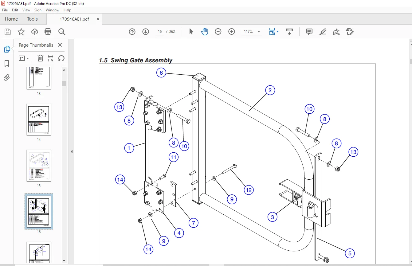
The information contained in this section is designed to aid the user in locating and identifying replacement parts. Component parts of various assemblies and sub-assemblies comprising the work platform are illustrated and accompanied by a descriptive parts list. Exploded drawings are used to show relative location of component parts in disassembly order. If a part cannot be found in this section, order by work platform model number and serial number, giving a complete description of the part.
Parts Ordering Information
When ordering replacement parts, the complete part number and description should be used to ensure proper identification and delivery of the desired item. This complete identification should also be used when requesting equipment information
Method Of Listing
- Parts are listed in order according to the reference number shown in the illustration, followed by a full description based upon the “NOUN FIRST” method. That is, the noun name of the part is listed first, then the modifying description information which serves to specifically identify the item. For example: PIN, Clevis. Assemblies or groups are shown at the beginning of a parts list and are identified with the letter references A, B, C, etc. Individual parts in these lists have corresponding letters after their description to identify which assembly or group it is used in. Individual parts without identifying letters are used in all the assemblies or group shown at the beginning of the parts list. Descriptions preceded with an (•) indicates a serviceable component or attaching hardware for the higher level assembly.
- If an index number initially starts with the letter “K”, for example “K1”, means it’s a kit. Any item(s) included in a kit will not have an index number.
IMAGES PREVIEW OF THE MANUAL:
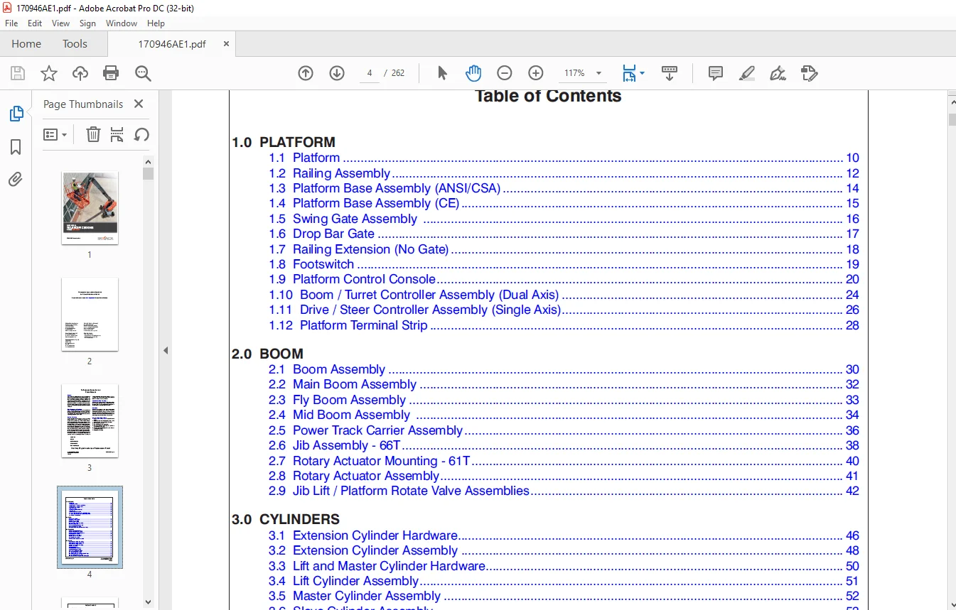
TABLE OF CONTENTS:
Skyjack SJ61T SJ66T Telescopic Booms Parts Manual 170946AE – PDF DOWNLOAD
Front Cover 1
Table of Contents 5
1 0 PLATFORM 9
1 1 Platform 10
1 2 Railing Assembly 12
1 3 Platform Base Assembly (ANSI/CSA) 14
1 4 Platform Base Assembly (CE) 15
1 5 Swing Gate Assembly 16
1 6 Drop Bar Gate 17
1 7 Railing Extension (No Gate) 18
1 8 Footswitch 19
1 9 Platform Control Console 20
1 10 Boom / Turret Controller Assembly (Dual Axis) 24
1 11 Drive / Steer Controller Assembly (Single Axis) 26
1 12 Platform Terminal Strip 28
2 0 BOOM 29
2 1 Boom Assembly 30
2 2 Main Boom Assembly 32
2 3 Fly Boom Assembly 33
2 4 Mid Boom Assembly 34
2 5 Power Track Carrier Assembly 36
2 6 Jib Assembly – 66T 38
2 7 Rotary Actuator Mounting – 61T 40
2 8 Rotary Actuator Assembly 41
2 9 Jib Lift / Platform Rotate Valve Assemblies 42
3 0 CYLINDERS 45
3 1 Extension Cylinder Hardware 46
3 2 Extension Cylinder Assembly 48
3 3 Lift and Master Cylinder Hardware 50
3 4 Lift Cylinder Assembly 51
3 5 Master Cylinder Assembly 52
3 6 Slave Cylinder Assembly 53
3 7 Jib Cylinder Assembly 54
3 8 Axle Lockout Cylinder Assembly 55
4 0 TURRET 57
4 1 Cowling Assembly – Engine Side 58
4 2 Cowling Assembly – Control Side 60
4 3 Cowling Assembly – Center 62
4 4 High Pressure Filter Assembly 63
4 5 Turret Assembly 64
4 6 Manifold Hardware 66
4 7 Main Manifold Assembly 68
4 8 Brake Manifold Assembly 70
4 9 Pressure Reducing Manifold 72
4 10 Rotary Manifold Assembly 74
4 11 Hydraulic Tank Assembly 76
4 12 No Generator and Oil Cooler Hose Fittings 78
4 13 Turret Swing Drive Assembly 79
4 14 Fuel Tank Assembly (GM Dual Fuel Engine) 80
4 15 Fuel Tank Assembly – Kubota Engine 82
4 16 Fuel Tank Assembly – Deutz Diesel Engine 84
4 17 Battery Cable Assembly 85
4 18 Battery and Lockout Switch Assembly 86
4 19 Auxiliary Pump 87
4 20 Base Control Box – Deutz TD2 9L Engine 88
4 21 Base Control Box – Deutz D2011 & GM Engines 92
4 22 Base Terminal Strip – Deutz TD2 9L Engine 96
4 23 Base Terminal Strip – Deutz D2011 & GM Engines 97
5 0 ELECTRICAL HARNESSES 99
5 1 Main Electrical Harness 100
5 2 Battery Cables 102
5 3 Control Cable Harnesses 104
5 4 Jib & Platform Rotate Harnesses 105
5 5 110/220V Outlet Harness 106
5 6 ECU Harnesses – Deutz D2011 107
5 7 Glow Plug Harness (Deutz TD2 9L Engine) 108
5 8 Glow Plug Harness (Deutz D2011 Engine) 109
5 9 Engine Interface Harness – Deutz TD2 9L Engine 110
5 10 Engine Interface Harness – Kubota WG2503 112
5 11 Engine Interface Harness – GM Engine 114
6 0 BASE 115
6 1 Base Assembly 116
6 2 Counterweight Assembly 118
6 3 Axle Hardware 120
6 4 Rear Axle Assembly 122
6 5 Differential Assembly – Rear Axle 124
6 6 Central Housing Assembly – Rear Axle 126
6 7 Gear Box – Rear Axle 128
6 8 Hydraulic Drive Motor 131
6 9 Front Axle Assembly 132
6 10 Differential Assembly – Front Axle 134
6 11 Central Housing Assembly – Front Axle 136
6 12 Steering Assembly 137
6 13 Trunnion Assembly – Front Axle 138
6 14 Axle Drive Shaft 139
6 15 Brake Assembly – Front & Rear Axle 140
6 16 Propane Tank Assembly 144
6 17 Tires 146
7 0 ENGINES 147
7 1 Engine Assembly – Deutz TD2 9L 148
7 2 Radiator Assembly – Deutz TD2 9L 152
7 3 Engine Assembly – Deutz D2011 154
7 4 Engine Assembly – GM Dual Fuel 158
7 5 Engine Assembly – Kubota WG2503 162
7 6 Radiator & Air Intake Assemblies – Kubota WG2503 168
7 7 Engine Tray Assembly 170
7 8 Drive and System Pump Assembly 172
7 9 Engine Coupling – Deutz 174
7 10 Engine Coupling – Kubota WG2503 175
8 0 HOSE CONNECTIONS 177
8 1 Standard Hose Numbering System 178
8 2 Hydraulic Hose Connection – Cylinders 180
8 3 Hydraulic Hose Connection – Control Compartment 182
8 4 Hydraulic Hose Connection – Pumps & Swing Drive 184
8 5 Hydraulic Hose Connection – Base and Axles 186
8 6 Fuel Line Hose Connection – Deutz TD2 9L Engine 188
8 7 Fuel Line Hose Connection – Deutz D2011 Engine 190
8 8 Fuel Line Hose Connection – GM Engine 192
8 9 Fuel Line Hose Connection – Kubota WG2503 Engine 194
8 10 Turret Grease Hose Connections 196
9 0 OPTIONAL EQUIPMENT 197
9 1 Generator and Oil Cooler – 3 5kW 198
9 2 Generator Assembly – 3 5kW 200
9 3 Oil Cooler with No Generator 202
9 4 Oil Cooler Assembly 203
9 5 Hydraulic Hose Connection – Generator and Oil Cooler – 3 5kW 204
9 6 Generator and Oil Cooler Wiring 206
9 7 Generator and Oil Cooler -12 kW 208
9 8 Generator Assembly – 12kW 210
9 9 Hydraulic Hose Connection – 12kW Generator and Oil Cooler 212
9 10 Welder and Mounting Assembly 214
9 11 Glazier Package Option 218
9 12 Cold Start Engine Option 220
9 13 Arctic Package Option 221
9 14 Block Heater – Deutz TD2 9L 222
9 15 Oil Quick Drain 223
9 16 SGM Assembly 224
9 17 SGE Assembly 226
9 18 External Platform Railing Assembly 228
9 19 Flashing Light 229
9 20 Air Hose To Platform Option 230
9 21 Diesel Scrubber 231
9 22 Control Box Cover 232
9 23 Positive Air Shut-Off Valve – Deutz TD2 9L 234
9 25 Telematics – Morey 238
9 26 Telematics – ZTR 239
10 0 LABELS 241
10 1 Label Kits 243
10 2 Labels – Platform Control Console 244
10 3 Labels – Front and Bottom 245
10 4 Labels – Engine Side 246
10 5 Labels – Controls Side 248
10 6 Labels – Controls Compartment 250
10 7 Labels – Engine Compartment 251
10 8 Labels – Platform 252
10 9 Labels – Engine Fuel 254
11 0 TABLES 255
11 1 Fluids 256
11 2 Grease Locations – Axle 257
11 3 Grease Locations – Gears 258
11 4 Filters 259
Customer Support: [email protected]
PLEASE NOTE:
- This is the SAME manual used by the dealers to troubleshoot any faults in your vehicle. This can be yours in 2 minutes after the payment is made.
- Contact us at [email protected] should you have any queries before your purchase or that you need any other service / repair / parts operators manual.
S.M