Skyjack SJ63 AJ+, SJ63 AJ Articulating Booms Service Manual 229043AAA – PDF DOWNLOAD
$26.95
Skyjack SJ63 AJ+, SJ63 AJ Articulating Booms Service Manual 229043AAA – PDF DOWNLOAD
serial numbers:
SJ63 AJ+: A302 000 001 – A302 999 999
SJ63 AJ: A302 000 001 – A302 999 999
SJ63 AJ: B302 000 001 – B302 999 999
Description
Skyjack SJ63 AJ+, SJ63 AJ Articulating Booms Service Manual 229043AAA – PDF DOWNLOAD
FILE DETAILS:
Skyjack SJ63 AJ+, SJ63 AJ Articulating Booms Service Manual 229043AAA – PDF DOWNLOAD
Language : English
Pages :196
Downloadable : Yes
File Type : PDF
DESCRIPTION:
Skyjack SJ63 AJ+, SJ63 AJ Articulating Booms Service Manual 229043AAA – PDF DOWNLOAD
serial numbers:
SJ63 AJ+: A302 000 001 – A302 999 999
SJ63 AJ: A302 000 001 – A302 999 999
SJ63 AJ: B302 000 001 – B302 999 999
Scheduled Maintenance Operator’s Responsibility for Maintenance;
SKYJACK is continuously improving and expanding product features on its equipment, therefore, specifications
and dimensions are subject to change without notice.
Aerial Platform and Mobile Elevating Work Platform (MEWP) Definition
A mobile device that has a positionable platform supported from ground level by a structure.
Purpose of Equipment
The SKYJACK Veritcal Mast series aerial platform are designed to transport and raise personnel, tools and materials
to overhead work areas.
Use of Equipment
The aerial platform is a highly maneuverable, mobile work station. Lifting and driving must be on a flat, level,
compacted surface.
Manuals:
Operating:
The operating manual is considered a fundamental part of the aerial platform. It is a very important way to
communicate necessary safety information to users and operators. A complete and legible copy of this manual
must be kept in the provided weather-resistant storage compartment on the aerial platform at all times.
Service & Maintenance:
The purpose of this is to provide the customer with the servicing and maintenance procedures essential for
the promotion of proper machine operation for its intended purpose.
All information in this manual should be read and understood before any attempt is made to service the machine.
The updated copy of the manuals are found on the company’s website: www.skyjack.com.
Operator:
The operator must read and completely understand both this operating manual and the safety panel label located
on the platform and all other warnings in this manual and on the aerial platform. Compare the labels on the aerial
platform with the labels found within this manual. If any labels are damaged or missing, replace them immediately.
IMAGES PREVIEW OF THE MANUAL:
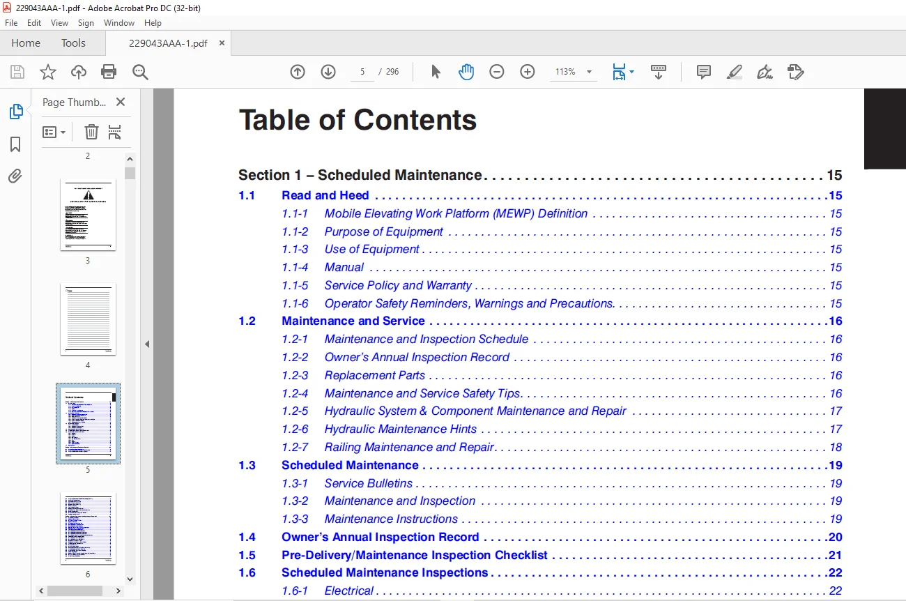
TABLE OF CONTENTS:
Skyjack SJ63 AJ+, SJ63 AJ Articulating Booms Service Manual 229043AAA – PDF DOWNLOAD
Table of Contents 5
Section 1 – Scheduled Maintenance 15
1 1 Read and Heed 15
1 1-1 Mobile Elevating Work Platform (MEWP) Definition 15
1 1-2 Purpose of Equipment 15
1 1-3 Use of Equipment 15
1 1-4 Manual 15
1 1-5 Service Policy and Warranty 15
1 1-6 Operator Safety Reminders, Warnings and Precautions 15
1 2 Maintenance and Service 16
1 2-1 Maintenance and Inspection Schedule 16
1 2-2 Owner’s Annual Inspection Record 16
1 2-3 Replacement Parts 16
1 2-4 Maintenance and Service Safety Tips 16
1 2-5 Hydraulic System & Component Maintenance and Repair 17
1 2-6 Hydraulic Maintenance Hints 17
1 2-7 Railing Maintenance and Repair 18
1 3 Scheduled Maintenance 19
1 3-1 Service Bulletins 19
1 3-2 Maintenance and Inspection 19
1 3-3 Maintenance Instructions 19
1 4 Owner’s Annual Inspection Record 20
1 5 Pre-Delivery/Maintenance Inspection Checklist 21
1 6 Scheduled Maintenance Inspections 22
1 6-1 Electrical 22
1 6-2 Hydraulic 22
1 6-3 Labels (B) 22
1 6-4 Limit switches (B) 22
1 6-5 Engine Compartment 23
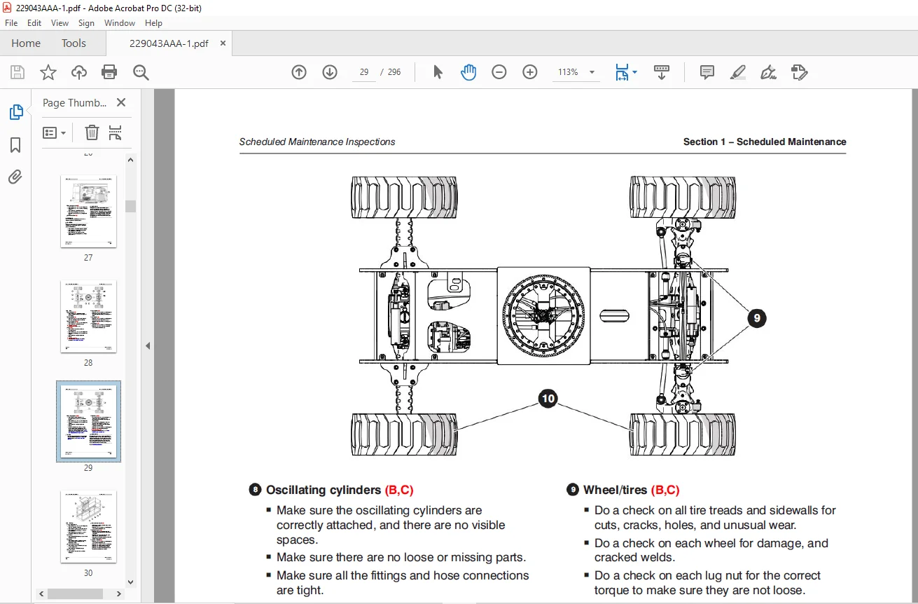
1 6-6 Base 28
1 6-7 Platform 30
1 6-8 Boom Assembly 31
1 6-9 Optional equipment (B) 32
1 7 Function Tests 33
Section 2 – Maintenance Tables and Diagrams 35
2 1 Standard Hose Numbering System 35
2 2 Torque Specifications for Fasteners (US Imperial) 37
2 3 Torque Specifications for Fasteners (Metric) 38
2 4 Torque Specifications for Hydraulic Couplings & Hoses 39
2 5 Axle Torque Specifications 40
2 6 Axles Maintenance Intervals 41
2 7 MEWP Torque Specifications 42
2 8 Maximum Platform Capacity 43
2 9 Tire Specifications 43
2 10 Floor Loading Pressure 44
2 11 Hydraulic Specifications & Gear Oil 45
2 12 Specifications & Features – Dimensions & Speeds 46
2 13 Engine Specifications 48
2 14 Dimension and Reach Diagrams – SJ63AJ 49
2 15 Axle Oscillation Diagrams 50
Section 3 – System Component Identification and Schematics 51
3 1 Electrical Symbol Chart 52
3 2 Hydraulic Symbol Chart 53
3 3 Wire Number and Color Code 54
3 4 Hydraulic Parts List 55
3 5 Electrical Component Parts List 59
3 6 Rotary Manifold Port Identification 62
3 7 Brake Manifold Port Identification 63
3 8 Drive and System Pump and Port Identifications 64
3 9 Drive Motor and Port Identifications 65
3 10 Jib Valve and Port Identifications 66
3 11 Main Manifold and Port Identifications 67
3 12 Main Manifold and Electrical Identifications 68
3 13 Main Manifold and Hydraulic Identifications 69
3 14 Main Electrical Harness and Fuel Level Switch Harness 70
3 15 ECU Engine Wiring Diagram – Deutz 71
3 16 Glow Plug Harnesses – Deutz D2011 72
3 17 Glow Plug Harnesses – Deutz TD2 9L 73
3 18 Engine Interface Harness – GM 74
3 19 Engine Interface Harness – Deutz TD2 9L 75
3 20 Lowering Throttle Valve Harness 76
3 21 Platform Harnesses 77
3 22 Platform Control Cables 78
3 23 Limit Switch Connections at the Base Control Box 79
3 24 Load Sensing Connections – CE & AS 80
3 25 All Motion Alarm Connections – CE & AS 81
3 26 SGE Wiring Diagram 82
3 27 Hydraulic Generator and Oil Cooler Wiring – Base Control Box 83
3 28 Generator Wiring – Upper Control Box 84
3 29 Welder Wiring – ANSI/CSA 85
3 30 Load Circuit Wiring 86
3 31 Positive Air Shutoff Harness 87
3 32 Hydraulic Schematic – ANSI/CSA 88
3 33 Hydraulic Schematic – CE & AS 89
3 34 Platform Control Box Wiring – ANSI/CSA 90
3 35 Platform Conrol Box Wiring – CE – Deutz TCD2 2 91
3 36 Platform Control Box Wiring – CE – Deutz TD2 9L & D2011 92
3 37 Platform Control Box Wiring – CE – Kubota WG2503 93
3 38 Platform Control Box Wiring – AS 94
3 39 Base Control Box Wiring – ANSI/CSA 95
3 40 Base Control Box Wiring – ANSI/CSA with Positive Air Shut-Off Option 96
3 41 Base Control Box Wiring – CE – Deutz TCD2 2 97
3 42 Base Control Box Wiring – CE – Deutz TD2 9L 98
3 43 Base Control Box Wiring – CE – Deutz D2011 99
3 44 Base Control Box Wiring – AS 100
3 45 Electrical Schematic – ANSI/CSA 101
3 46 Electrical Schematic – CE – Deutz TCD2 2 102
3 47 Electrical Schematic – CE – Deutz TD2 9 103
3 48 Electrical Schematic – CE – Deutz D2011 104
3 49 Electrical Schematic – CE – Kubota WG2503 105
3 50 Electrical Schematic – AS – Deutz D2011 106
3 51 Engine Electrical Schematic – Deutz TD2 9L 107
3 52 Engine Interface Wiring – Deutz TD2 9L 108
3 53 Engine Electrical Schematic – Deutz D2011 109
3 54 Engine Electrical Schematic – Kubota WG2503 110
3 55 Engine Electrical Schematic – Deutz TCD2 2 111
3 56 Engine Interface Harness – Deutz TCD2 2 112
Section 4 – Troubleshooting Information 113
4 1 Introduction 113
4 2 Electrical System – ANSI/CSA 114
4 2-1 All Controls are Inoperative from the Base or Platform Console 114
4 2-2 All Controls are Inoperative from the Base Console 116
4 2-3 The Engine will not Crank from the Base or Platform 116
4 2-4 The Engine will not Crank from the Base 117
4 2-5 The Engine will not Crank from the Platform 117
4 2-6 The Boom Controls are Inoperative (Drive Operates) 117
4 2-7 No Boom Up from the Base or Platform Controls 118
4 2-8 No Boom Up from the Base Console 118
4 2-9 No Boom Up from the Platform Console 118
4 2-10 No Boom Down from the Base or Platform Consoles 118
4 2-11 No Boom Down from the Base Console 119
4 2-12 No Boom Down from the Platform Console 119
4 2-13 No Turret Rotate Right from the Base or Platform Consoles 119
4 2-14 No Turret Rotate Right from the Base Console 119
4 2-15 No Turret Rotate Right from the Platform Console 120
4 2-16 No Turret Rotate Left from the Base or Platform Consoles 120
4 2-17 No Turret Rotate Left from the Base Console 120
4 2-18 No Turret Rotate Left from the Platform Console 120
4 2-19 No Riser Up from the Base or Platform Consoles 121
4 2-20 No Riser Up from the Base Console 121
4 2-21 No Riser Up from the Platform Console 121
4 2-22 No Riser Down from the Base or Platform Consoles 121
4 2-23 No Riser Down from the Base Console 122
4 2-24 No Riser Down from the Platform Console 122
4 2-25 No Telescope Out from the Base or Platform Consoles 122
4 2-26 No Telescope Out from the Base Console 122
4 2-27 No Telescope Out from the Platform Console 123
4 2-28 No Telescope In from the Base or Platform Consoles 123
4 2-29 No Telescope In from the Base Console 123
4 2-30 No Telescope In from the Platform Console 123
4 2-31 No Platform Level Up from the Base or Platform Consoles 124
4 2-32 No Platform Level Up from the Base Console 124
4 2-33 No Platform Level Up from the Platform Console 124
4 2-34 No Platform Level Down from the Base or Platform Consoles 124
4 2-35 No Platform Level Down from the Base Console 125
4 2-36 No Platform Level Down from the Platform Console 125
4 2-37 No Platform Rotate or Jib Functions from the Base or Platform Consoles 125
4 2-38 No Platform Rotate Right from the Base or Platform Consoles 126
4 2-39 No Platform Rotate Right from the Base Console 126
4 2-40 No Platform Rotate Right from the Platform Console 126
4 2-41 No Platform Rotate Left from the Base or Platform Consoles 127
4 2-42 No Platform Rotate Left from the Base Console 127
4 2-43 No Platform Rotate Left from the Platform Console 127
4 2-44 No Jib Up from the Base or Platform Consoles 127
4 2-45 No Jib Up from the Base Console 128
4 2-46 No Jib Up from the Platform Console 128
4 2-47 No Jib Down from the Base or Platform Consoles 128
4 2-48 No Jib Down from the Base Console 128
4 2-49 No Jib Down from the Platform Console 129
4 2-50 No Drive or Steer Functions 129
4 2-51 No Forward or Reverse Drive 129
4 2-52 No Forward Drive 129
4 2-53 No Reverse Drive 130
4 2-54 The Brake will not Release 130
4 2-55 No Left Steer 130
4 2-56 No Right Steer 131
4 2-57 The Directon Sensing is Inoperative 131
4 2-58 The Load Sense Indicates Overload or Overload Warning with the Platform Empty or Below Weight 132
4 2-59 The Overload Indicator Light does not Turn On when the Platform is Overloaded 132
4 2-60 The Audible Alarm does not Turn On with the Platform Overloaded 132
4 3 Electrical System – CE & AS 133
4 3-1 All Controls are Inoperative 133
4 3-2 No Power To Platform 134
4 3-3 No Power to Base 134
4 3-4 The Engine Will Not Crank from the Base 135
4 3-5 The Engine Will Not Crank from the Platform 135
4 3-6 The Engine Will Not Crank from the Platform or Base (Deutz Diesel) 135
4 3-7 The Engine Will Not Crank from the Platform or Base when equipped with Elevate/Trackunit Telematics Ready 136
4 3-8 The Engine Cranks but Will Not Start (Deutz Diesel) 137
4 3-9 The Engine Will Not Crank from the Platform or Base Control (GM Dual Fuel) 137
4 3-10 The Engine Cranks but Will Not Start (GM Dual Fuel) 138
4 3-11 The Glow Plug Circuit is Inoperative 140
4 3-12 All Controls are Inoperative from the Base Console 141
4 3-13 No Main Boom Down, Riser Down or Turret Rotate from Base Control Console 142
4 3-14 No Boom Up from the Base Control Console 142
4 3-15 No Boom Down from the Base Control Console 143
4 3-16 No Riser Up from the Base Control Console 143
4 3-17 No Riser Down from the Base Control Console 144
4 3-18 No Turret Rotate Left from the Base Control Console 144
4 3-19 No Turret Rotate Right from the Base Control Console 145
4 3-20 No Telescope Retract from the Base Control Console 145
4 3-21 No Telescope Extend from the Base Control Console 146
4 3-22 No Platform Rotate Left or Right 146
4 3-23 Platform Rotates too Quickly 147
4 3-24 No Platform Rotate Left from the Base Control Console 147
4 3-25 No Platform Rotate Right from the Base Control Console 148
4 3-26 No Jib Up from the Base Control Console 149
4 3-27 No Jib Down from the Base Control Console 149
4 3-28 No Manual Platform Level Up from the Base Control Console 150
4 3-29 No Manual Platform Level Down from the Base Control Console 150
4 3-30 All Controls are Inoperative from the Platform Control Console 150
4 3-31 No Boom Up from the Platform Control Console 152
4 3-32 No Boom Down from the Platform Control Console 152
4 3-33 No Riser Up from the Platform Control Console 153
4 3-34 No Riser Down from the Platform Control Console 154
4 3-35 No Turret Left from the Platform Control Console 155
4 3-36 No Turret Right from the Platform Control Console 155
4 3-37 No Toggle Switch Functions from the Platform Control Console 156
4 3-38 No Telescope In from the Platform Control Console 156
4 3-39 No Telescope Out from the Platform Control Console 157
4 3-40 No Platform Rotate Left from the Platform Control Console 158
4 3-41 No Platform Rotate Right from the Platform Control Console 159
4 3-42 No Jib Up from the Platform Control Console 160
4 3-43 No Jib Down from the Platform Control Console 161
4 3-44 No Manual Platform Level Up from the Platform Control Console 162
4 3-45 No Manual Platform Level Down from the Platform Control Console 163
4 3-46 Mid Throttle Inoperative 164
4 3-47 High Throttle Inoperative 165
4 3-48 Brake will not Release 166
4 3-49 Differential Lock will not Engage 166
4 3-50 Differential Lock Engages Momentarily but will not stay Engaged 167
4 3-51 No Drive and Steer 167
4 3-52 No Forward Drive 168
4 3-53 No Reverse Drive 168
4 3-54 No High Speed Drive 169
4 3-55 No Elevated Drive 170
4 3-56 No Left Steer 171
4 3-57 No Right Steer 171
4 3-58 Direction Sensing Inoperative 172
4 4 Load Sensing System – CE & AS 173
4 4-1 Green Power LED is not Flashing 173
4 4-2 Load Cell red Alarm LED is ON (with platform empty) 173
4 4-3 Red Error LED is ON 173
4 4-4 Load Cell red Alarm LED is OFF (with platform overloaded) 173
4 4-5 Platform Indicator Light does not turn ON 173
4 4-6 Audible Alarm does not turn ON 174
4 4-7 Boom and Drive Functions are Enabled (with boom extended) 174
4 5 Hydraulic System – ANSI/CSA 175
4 5-1 All Controls are Inoperative 175
4 5-2 All Boom Functions are Inoperative 175
4 5-3 No Main Boom Up 175
4 5-4 No Main Boom Down 175
4 5-5 No Riser Boom Up 176
4 5-6 No Riser Boom Down 176
4 5-7 No Turret Rotate Left 177
4 5-8 No Turret Rotate Right 177
4 5-9 No Boom Extend 178
4 5-10 No Boom Retract 178
4 5-11 No Jib Up 178
4 5-12 No Jib Down 179
4 5-13 No Platform Rotation Right 179
4 5-14 No Platform Rotation Left 179
4 5-15 The Platform will not Level Down Manually 180
4 5-16 The Platform will not Level Up Manually 180
4 5-17 The Brake will not Release 181
4 5-18 The Brake will not Engage 181
4 5-19 The Differential Lock will not Engage 182
4 5-20 No Drive Forward or Reverse 182
4 5-21 No Forward Drive 182
4 5-22 No Reverse Drive 182
4 5-23 No High Speed Drive 183
4 5-24 No Right Steer 183
4 5-25 No Left Steer 183
4 5-26 The Axle will not Oscillate 183
4 5-27 Axle Will Not Lock 184
4 6 Hydraulic System – CE & AS 185
4 6-1 All Controls are Inoperative 185
4 6-2 All Boom Functions are Inoperative 185
4 6-3 No Main Boom Up 185
4 6-4 No Main Boom Down 185
4 6-5 No Riser Boom Up 186
4 6-6 No Riser Boom Down 186
4 6-7 No Turret Rotate Left 187
4 6-8 No Turret Rotate Right 187
4 6-9 No Boom Extend 188
4 6-10 No Boom Retract 188
4 6-11 No Jib Up 188
4 6-12 Jib Up/ Down Slow 189
4 6-13 No Jib Down 189
4 6-14 No Platform Rotation Right 189
4 6-15 No Platform Rotation Left 189
4 6-16 Platform Rotates too Quickly 190
4 6-17 Platform will not Level Down Manually 190
4 6-18 Platform will not Level Up Manually 190
4 6-19 Brake will not Release 191
4 6-20 Brake will not Engage 191
4 6-21 Differential Lock will not Engage 192
4 6-22 No Drive Forward or Reverse 192
4 6-23 No Forward Drive 192
4 6-24 No Reverse Drive 192
4 6-25 No High Speed Drive 193
4 6-26 No Right Steer 193
4 6-27 No Left Steer 193
4 6-28 The Axle Will Not Oscillate 193
4 6-29 The Axle Will Not Lock 194
Section 5 – Procedures 195
5 1 General 195
5 1-1 Safety and Workmanship 195
5 2 Platform 196
5 2-1 Human Machine Interface (HMI) 196
5 2-2 User Interface Keys 196
5 2-3 OCM Character Functions Charts 197
5 2-4 OCM Function Channel Names – CE & AS 197
5 2-5 OCM Operating Values Chart – CE & AS 198
5 2-6 How to Select Functionality – CE & AS 199
5 2-7 How to View OCM Operation – CE & AS 200
5 2-8 How to Unlock and Modify OCM Settings – CE & AS 201
5 2-9 OCM Pin Reference – ANSI/CSA 202
5 2-10 OCM Pin Voltage Reference – CE & AS 208
5 2-11 Platform Controller Voltage References 211
5 3 Load Sensing System – CE & AS 213
5 3-1 Load Sensing System Overload Status 213
5 3-2 Verify Proper Operation of the Load Sensing System 214
5 3-3 Calibration of Load Sensing System (with “Teach In” Handset) 215
5 4 Boom 216
5 4-1 Check Wear Pads 216
5 4-2 Shim Wear Pads 216
5 4-3 Cable Carrier Repair 216
5 4-4 Rotary Actuator Bolt Torque Procedure 216
5 4-5 Boom Section Wear Pad Replacement 217
5 4-6 Platform and Jib Boom Removal 218
5 4-7 Operating Machine Functions from the Base Controls 219
5 4-8 Fly Boom Removal 219
5 4-9 Change Wear Pads on Extension Cylinder Support 221
5 4-10 Fly Boom Installation 222
5 4-11 Platform/Jib Installation 223
5 4-12 Platform Control Console Connection 223
5 4-13 Extension Cylinder Removal 224
5 4-14 Extension Cylinder Installation 227
5 4-15 Main Boom Lift Cylinder Removal 228
5 4-16 Lift Cylinder Installation 229
5 4-17 Riser Cylinder Removal 230
5 4-18 Riser Cylinder Installation 230
5 4-19 Replace Limit Switch – Main Boom 231
5 4-20 Test Main Boom Limit Switch 232
5 4-21 Replace Limit Switch – Riser Boom 232
5 4-22 Test Riser Boom Limit Switch 233
5 4-23 Replace Limit Switch – Fly Boom 233
5 4-24 Test Fly Boom Limit Switch 234
5 5 Turret 235
5 5-1 Check and Replace the High Pressure Filter 235
5 5-2 Adjust the Turret Rotation Gear Backlash 235
5 5-3 Swing Drive Motor Removal 236
5 5-4 Check the Swing Drive Oil 237
5 5-5 Change the Swing Drive Oil 237
5 5-6 Check Rotation Bearing for Axial Wear 238
5 5-7 Turret Rotation Gear Bolt Torque Sequence 238
5 5-8 Electronic Tilt Switch Setup Procedure 239
5 5-9 Battery Replacement 241
5 6 Deutz Diesel Engine 242
5 6-1 Replace Engine Oil and Filter 242
5 6-2 Replace the Fuel Filter 243
5 6-3 Replace the Air Filter 243
5 6-4 Check the Engine Belt 243
5 6-5 Check the Oil Cooler (Deutz D2011 only) 243
5 6-6 Deutz TD2 9L Fault Codes 244
5 7 Kubota WG2503 Dual Fuel Engine 264
5 7-1 Engine Parameter Display (KAntrak 1700) 264
5 7-2 Diagnostic Trouble Codes 265
5 7-3 ECU Pin Reference Chart (Kubota WG2503) 270
5 7-4 Fuse Box (Kubota WG2503) 271
5 7-5 MAP Sensor (Kubota WG2503) 272
5 7-6 IAT Sensor (Kubota WG2503) 272
5 7-7 ECT (Kubota WG2503) 273
5 7-8 TPS & Engine Speed (Kubota WG2503) 273
5 7-9 Fuel Temperature Sensor (Kubota WG2503) 274
5 7-10 Oil Pressure Sensor (Kubota WG2503) 274
5 8 Hydraulic Tank 275
5 8-1 Change the Hydraulic Tank Filter 275
5 8-2 Change the Hydraulic Oil 275
5 9 Manifold and Hydraulic Pumps 276
5 9-1 Hydraulic Brake Pressure Adjustment 276
5 9-2 Hydraulic System Relief Valve Adjustment (RV1) 277
5 9-3 Turret Rotate Relief Valve Adjustment (RV2) 277
5 9-4 Platform Level Relief Valve Adjustment (RV3) 278
5 9-5 Riser Boom Down Relief Valve Adjustment (RV4) 278
5 9-6 Main Boom Down Relief Valve Adjustment (RV5) 279
5 9-7 Fly Boom Relief Valve Adjustment (RV6) 279
5 9-8 Test Charge Pump Pressure on Drive Pump (RV10) 280
5 9-9 Test Forward Drive Pressure on Drive Pump 280
5 9-10 Test Reverse Drive Pressure on Drive Pump 281
5 9-11 Hydraulic Standby Pressure Adjustment 281
5 9-12 Hydraulic High Pressure Adjustment 282
5 10 Axles 283
5 10-1 Change the Oil in the Axles 283
5 10-2 Check the Oil Level in the Torque Hubs 283
5 10-3 Change the Oil in the Torque Hubs 283
5 10-4 Check the Oil Level in the Axle Gearbox 284
5 10-5 Change the Oil in the Axle Gearbox 284
5 10-6 Oscillating Cylinder Bolt Replacement 285
5 10-7 Oscillating Cylinder Replacement 285
5 10-8 Bleed the Oscillating Axle Cylinders 287
5 10-9 Pin Brake Adjustments 287
5 10-10 Brake Inspection 289
5 11 Grease Points 290
5 11-1 Grease the Turret Ring Gear 290
5 11-2 Grease the Turret Swing Drive 290
5 11-3 Grease the Axles 291
5 11-4 Grease the Drive Shaft 291
5 12 Options 292
5 12-1 Generator Troubleshooting 292
5 12-2 Generator Frequency/Voltage Check & Adjustment 293
Contact us: [email protected]
PLEASE NOTE:
- This is the same manual used by the dealers to diagnose and troubleshoot your vehicle
- You will be directed to the download page as soon as the purchase is completed. The whole payment and downloading process will take anywhere between 2-5 minutes
- Need any other service / repair / parts manual, please feel free to contact [email protected] . We still have 50,000 manuals unlisted
S.M