Trusted Business
Verified & Licensed
Virus Free Files
100% Safe Downloads
Secure Payment
SSL Protected
Instant Delivery
Available Immediately
Skyjack SJ63AJ Articulating Booms Parts Manual 159762AG – PDF DOWNLOAD
$28.95
Skyjack SJ63AJ Articulating Booms Parts Manual 159762AG – PDF DOWNLOAD
Instant PDF Download
Available immediately
Save to Your Device
Download & keep forever
Antivirus Scanned
100% virus-free
Trusted Worldwide
175,000+ customers
Description
Skyjack SJ63AJ Articulating Booms Parts Manual 159762AG – PDF DOWNLOAD
FILE DETAILS:
Skyjack SJ63AJ Articulating Booms Parts Manual 159762AG – PDF DOWNLOAD
Language : English
Pages : 220
Downloadable : Yes
File Type : PDF
DESCRIPTION:
Skyjack SJ63AJ Articulating Booms Parts Manual 159762AG – PDF DOWNLOAD
General:
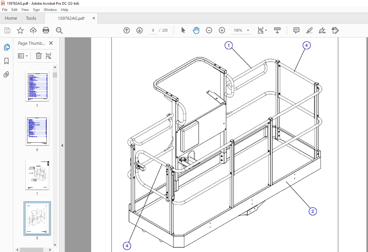
The information contained in this section is designed to aid the user in locating and identifying
replacement parts. Component parts of various assemblies and sub-assemblies comprising the
work platform are illustrated and accompanied by a descriptive parts list. Exploded drawings are
used to show relative location of component parts in disassembly order. If a part cannot be found
in this section, order by work platform model number and serial number, giving a complete
description of the part.
Parts Ordering Information:
When ordering replacement parts, the complete part number and description should be used to
ensure proper identification and delivery of the desired item. This complete identification should
also be used when requesting equipment information.
When ordering replacement parts, the complete part number and description should be used to
ensure proper identification and delivery of the desired item. This complete identification should
also be used when requesting equipment information.
Method Of Listing:
Parts are listed in order according to the reference number shown in the illustration,
followed by a full description based upon the “NOUN FIRST” method. That is, the noun name
of the part is listed first, then the modifying description information which serves to
specifically identify the item. For example: PIN, Clevis. Assemblies or groups are shown at the
beginning of a parts list and are identified with the letter references A, B, C, etc. Individual
parts in these lists have corresponding letters after their description to identify which assembly
or group it is used in. Individual parts without identifying letters are used in all the assemblies
or group shown at the beginning of the parts list. Descriptions preceded with an (•) indicates
a serviceable component or attaching hardware for the higher level assembly. If
an index number initially starts with the letter “K”, for
example “K1”, means it’s a kit. Any item(s) included in a kit will not have an index number.
Quantities (Units Per Assy.) :
The quantities of each part that are required to
complete the assembly. If quantity is (AR), it is understood that the quantity may vary when
machine is equipped with certain options. Order quantity as needed.
complete the assembly. If quantity is (AR), it is understood that the quantity may vary when
machine is equipped with certain options. Order quantity as needed.
Hardware :
Standard screws, washers, nuts, etc. are not
identified by a reference number. These parts are known as COMMON HARDWARE items and appear
indented under the major items with which they are used. They should be ordered separately as
listed, since they are not component parts of the pieces they attach to.
identified by a reference number. These parts are known as COMMON HARDWARE items and appear
indented under the major items with which they are used. They should be ordered separately as
listed, since they are not component parts of the pieces they attach to.
How To Order Repair Parts:
1. Address all orders to your local SKYJACK dealer.
2. Specify model and serial number of the work platform (found on the serial number
plate).
3. List the quantity needed.
4. List the length needed (if bulk item).
5. List the part number and description as shown in this manual for each item.
6. Show billing and shipping address and name of individual if possible.
7. Suggest best routing.
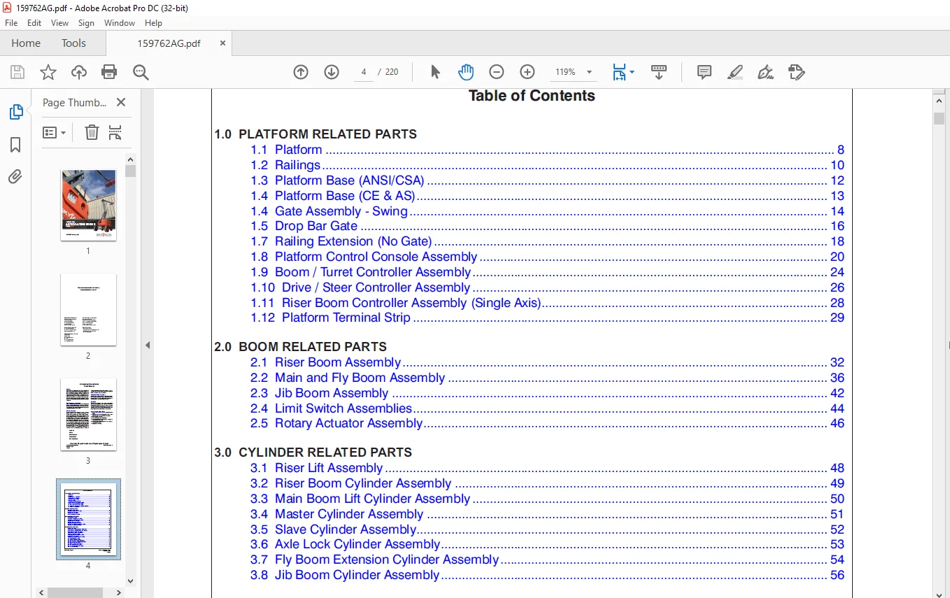
TABLE OF CONTENTS:
Skyjack SJ63AJ Articulating Booms Parts Manual 159762AG – PDF DOWNLOAD
Front Cover...........................................................  1
Table of Contents.....................................................  4
1.0  PLATFORM RELATED PARTS...........................................  7
	1.1  Platform.....................................................  8
	1.2  Railings..................................................... 10
	1.3  Platform Base (ANSI/CSA)..................................... 12
	1.4  Platform Base (CE & AS)...................................... 13
	1.4  Gate Assembly - Swing........................................ 14
	1.5  Drop Bar Gate................................................ 16
	1.7  Railing Extension (No Gate).................................. 18
	1.8  Platform Control Console Assembly............................ 20
	1.9  Boom / Turret Controller Assembly............................ 24
	1.10  Drive / Steer Controller Assembly........................... 26
	1.11  Riser Boom Controller Assembly (Single Axis)................ 28
	1.12  Platform Terminal Strip..................................... 29
2.0  BOOM RELATED PARTS............................................... 31
	2.1  Riser Boom Assembly.......................................... 32
	2.2  Main and Fly Boom Assembly................................... 36
	2.3  Jib Boom Assembly............................................ 42
	2.4  Limit Switch Assemblies...................................... 44
	2.5  Rotary Actuator Assembly..................................... 46
3.0  CYLINDER RELATED PARTS........................................... 47
	3.1  Riser Lift Assembly.......................................... 48
	3.2  Riser Boom Cylinder Assembly................................. 49
	3.3  Main Boom Lift Cylinder Assembly............................. 50
	3.4  Master Cylinder Assembly..................................... 51
	3.5  Slave Cylinder Assembly...................................... 52
	3.6  Axle Lock Cylinder Assembly.................................. 53
	3.7  Fly Boom Extension Cylinder Assembly......................... 54
	3.8  Jib Boom Cylinder Assembly................................... 56
4.0  TURRET RELATED PARTS............................................. 59
	4.1  Turret Assembly.............................................. 60
	4.2  Cowling Assembly Mounting - Engine Side...................... 62
	4.3  Cowling Assembly Mounting - Controls Side.................... 64
	4.4  Cowling Assembly - Engine Side............................... 66
	4.5  Cowling Assembly - Controls Side............................. 67
	4.6  Counterweight Assembly....................................... 68
	4.7  Additional Counterweight Assembly............................ 69
	4.8  Engine Tray Assembly......................................... 70
	4.9  High Pressure Shuttle Valve Assembly......................... 71
	4.10  Main Manifold Assembly...................................... 72
	4.11  Brake Manifold Assembly..................................... 74
	4.12  Fuel Tank Assembly - Deutz Engine........................... 76
	4.13  Fuel Tank Assembly - Dual Fuel Engine....................... 79
	4.14  Hydraulic Tank Assembly..................................... 80
	4.15  High Pressure Filter Assembly............................... 82
	4.16  Turret Swing Drive Assembly................................. 83
	4.17  Base Control Console Assembly............................... 84
	4.18  Base Terminal Strip......................................... 88
	4.19  Emergency Power Unit........................................ 89
	4.20  Battery Assembly............................................ 90
	4.21  Grease Line Hose Assembly................................... 91
5.0  ELECTRICAL HARNESS RELATED PARTS................................. 93
	5.1  Main Electrical Harness and Fuel Level Switch Harness........ 94
	5.2  Lowering Throttle Valve Harness.............................. 96
	5.3  Deutz ECU Harness............................................ 97
	5.4  Cable Harnesses.............................................. 98
	5.5  Control Cable Harnesses......................................100
	5.6  Glow Plug Harness - Deutz Engine.............................101
	5.7  110/220V Outlet Assembly.....................................102
	5.8  Engine Interface Harness - Dual Fuel Engine..................103
	5.9  Rotate Select Harness........................................104
6.0  BASE RELATED PARTS...............................................105
	6.1  Base Assembly................................................106
	6.2  Axle Assembly Hardware - Front...............................108
	6.3  Axle Assembly Hardware - Rear................................109
	6.4  Front Axle Assembly..........................................110
	6.5  Differential Assembly - Front Axle...........................112
	6.6  Central Housing Assembly - Front Axle........................114
	6.7  Steering Assembly - Front Axle...............................115
	6.8  Trunnion Assembly - Front Axle...............................116
	6.9  Axle Drive Shaft.............................................117
	6.10  Rear Axle Assembly (with Gear Box)..........................118
	6.11  Differential Assembly - Rear Axle (with Gear Box)...........120
	6.12  Central Housing Assembly - Rear Axle (with Gear Box)........123
	6.13  Gear Box - Rear Axle........................................124
	6.14  Brakes Assembly - Front and Rear Axle.......................126
	6.15  Rotary Manifold Assembly....................................128
	6.16  Propane Tank Assembly.......................................130
	6.17  Tire Assemblies.............................................132
7.0  ENGINE RELATED PARTS.............................................135
	7.1  Engine Assembly - Deutz Engine...............................136
	7.2  Engine Assembly - GM Engine..................................140
	7.3  Drive Pump and System Pump Assembly..........................144
	7.4  Engine Coupling Assembly.....................................146
8.0  HOSE CONNECTION RELATED PARTS....................................147
	8.1  Standard Hose Numbering System...............................148
	8.2  Hydraulic Hose Connection - Turret...........................150
	8.3  Hydraulic Hose Connection - Chassis..........................152
	8.4  Hydraulic Hose Connection - Drive Pump and System Pump.......154
	8.5  Hydraulic Hose Connection - Boom.............................156
	8.6  Fuel Line Connection - Deutz Engine..........................159
	8.7  Fuel Line Connection - Dual Fuel Engine......................160
9.0  OPTIONAL EQUIPMENT...............................................163
	9.1  Diesel Scrubber..............................................164
	9.2  All Motion Alarm.............................................165
	9.3  Air Hose to Platform.........................................166
	9.4  Hostile Environment Kit......................................168
	9.5  Platform Control Box Cover...................................170
	9.6  Hydraulic Oil Cooler Assembly................................172
	9.7  Hydraulic Hose Connection - Hydraulic Oil Cooler Assembly....173
	9.8  Hydraulic Oil Cooler Wiring..................................174
	9.9  Generator Assembly (3,500W)..................................176
	9.10  Generator Assembly (12,000W)................................178
	9.11  Hydraulic Hose Connection - Generator Assembly (3,500W).....180
	9.12  Hydraulic Hose Connection - Generator Assembly (12,000W)....181
	9.13  Generator Wiring............................................182
	9.14  Welder and Mounting Assembly................................184
	9.15  Glazier Package Assembly....................................188
	9.16  Cold Start Assembly.........................................190
	9.17  Arctic Package Assembly.....................................191
	9.18  Working Lights Assembly.....................................192
	9.19  External Platform Railing Assembly..........................194
	9.20  Pipe Rack Assembly..........................................196
	9.21  Flashing Amber Light Assembly...............................197
	9.22  SGM Assembly................................................198
	9.23  SGE Assembly................................................200
10.0  LABELS..........................................................203
	10.1  Label Kits..................................................203
	10.2  Labels - Platform Control Console...........................204
	10.3  Labels - Front and Back.....................................205
	10.4  Labels - Engine Side........................................206
	10.5  Labels - Controls Side......................................208
	10.6  Labels - Engine Compartment.................................210
	10.7  Labels - Controls Compartment...............................211
	10.8  Labels - Operator Platform..................................212
11.0  TABLES..........................................................215
	11.1  Boom Fluids Table...........................................216
	11.2  Boom Grease Locations - Axle Grease Table...................217
	11.3  Boom Grease Locations - Gear Grease Table...................218
IMAGES PREVIEW OF THE MANUAL:
Need help? Contact: [email protected]
https://vimeo.com/877758069?share=copy
PLEASE NOTE:
- This is the SAME exact manual used by your dealers to fix your vehicle.
- The same can be yours in the next 2-3 mins as you will be directed to the download page immediately after paying for the manual.
- Any queries / doubts regarding your purchase, please feel free to contact [email protected]
S.V