Skyjack SJ6826 RT, SJ6832 RT Rough Terrain Scissors Service Manual 167955AFA – PDF DOWNLOAD
$27.95
Skyjack SJ6826 RT, SJ6832 RT Rough Terrain Scissors Service Manual 167955AFA – PDF DOWNLOAD
SJ 68XXRT: 37004671 and 37299999
Description
Skyjack SJ6826 RT, SJ6832 RT Rough Terrain Scissors Service Manual 167955AFA – PDF DOWNLOAD
FILE DETAILS:
Skyjack SJ6826 RT, SJ6832 RT Rough Terrain Scissors Service Manual 167955AFA – PDF DOWNLOAD
Language : English
Pages : 145
Downloadable : Yes
File Type : PDF
DESCRIPTION:
Skyjack SJ6826 RT, SJ6832 RT Rough Terrain Scissors Service Manual 167955AFA – PDF DOWNLOAD
SJ 68XXRT: 37004671 and 37299999
1.1 Read and Heed:
Skyjack is continuously improving and expanding product features on its equipment, therefore,
specifications and dimensions are subject to change without notice.
A mobile device that has a positionable platform supported from ground level by a structure.
The Skyjack SJ Compact Rough Terrain Series MEWPs are designed to transport and raise personnel,
tools and materials to overhead work areas.
The MEWP is a highly maneuverable, mobile work station. Work platform elevation and elevated
driving must only be done on a firm, level surface.
Operating Manual: The operating manual is considered a fundamental part of the aerial platform. It
is a very important way to communicate necessary safety information to users and operators. A
complete and legible copy of this manual must be kept in the provided weather-resistant storage
compartment on the aerial platform at all times.
Service & Maintenance: The purpose of this is to provide the customer with the servicing and
maintenance procedures essential for the promotion of proper machine operation for its intended
purpose.
All information in this manual should be read and understood before any attempt is made to service
the machine.
1.1-5 Service Policy and Warranty
Skyjack warrants each new product to be free of defective parts and workmanship for the first 2
years or 3000 hours, whichever occurs first. Any defective part will be replaced or repaired by
your local Skyjack dealer at no charge for parts or labor. In addition,
all products have a 5 year structural warranty. Contact the Skyjack Service Department for warranty
statement extensions or exclusions.
Operator safety is Skyjack’s priority. The operator should comply with all applicable
safety-related reminders, warnings and precautions found in the Operating Manual. They should be
read and understood completely before operating the aerial platform.
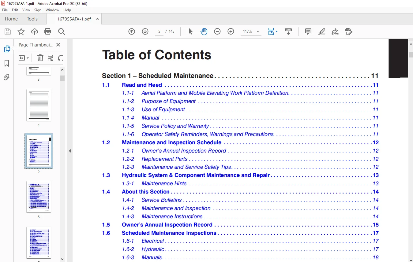
TABLE OF CONTENTS:
Skyjack SJ6826 RT, SJ6832 RT Rough Terrain Scissors Service Manual 167955AFA – PDF DOWNLOAD
Section 1 – Scheduled Maintenance 11
1 1 Read and Heed 11
1 1-1 Aerial Platform and Mobile Elevating Work Platform Definition 11
1 1-2 Purpose of Equipment 11
1 1-3 Use of Equipment 11
1 1-4 Manual 11
1 1-5 Service Policy and Warranty 11
1 1-6 Operator Safety Reminders, Warnings and Precautions 11
1 2 Maintenance and Inspection Schedule 12
1 2-1 Owner’s Annual Inspection Record 12
1 2-2 Replacement Parts 12
1 2-3 Maintenance and Service Safety Tips 12
1 3 Hydraulic System & Component Maintenance and Repair 13
1 3-1 Maintenance Hints 13
1 4 About this Section 14
1 4-1 Service Bulletins 14
1 4-2 Maintenance and Inspection 14
1 4-3 Maintenance Instructions 14
1 5 Owner’s Annual Inspection Record 15
1 6 Scheduled Maintenance Inspections 17
1 6-1 Electrical 17
1 6-2 Hydraulic 17
1 6-3 Manuals 18
1 6-4 Labels 18
1 6-5 Limit Switches 18
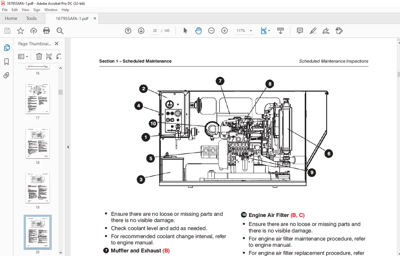
1 6-6 Engine Compartment 18
1 6-7 Hydraulic / Fuel Compartment 21
1 6-8 Platform Assembly 22
1 6-9 Lifting Mechanism 23
1 6-10 Base 27
1 7 Function Tests 29
Section 2 – Specifications 31
2 1 Specifications and Features 31
2 2 Floor Load Calculation 32
2 4 Floor Loading Pressure 33
2 3 Maximum Platform Capacities 33
2 5 Fluid Specifications 34
Table of Contents
5
SJ6826 RT / SJ6832 RT 167955AFA
2 6 Torque Specifications 35
2 7 Torque Specifications for Fasteners (Imperial) 36
2 8 Torque Specifications for Fasteners (Metric) 37
2 9 Torque Specifications for Hydraulic Couplings & Hoses 38
Section 3 – System Component Identification and Schematics 39
3 1 Hydraulic Symbol Chart 40
3 2 Electrical Symbol Chart 41
3 3 AC Cord Color Code 42
3 4 Hydraulic Schematic Parts List 43
3 5 Electrical Parts List 45
3 6 Hydraulic Schematic S/N 37006450 and above 50
3 7 Hydraulic Schematic S/N 37006449 and below 51
3 8 Hydraulic Manifold Valve Port Identification 52
3 9 Hydraulic Manifold Valve Assemblies and Port Identification 53
3 10 Control Box Wiring Diagram 54
3 11 Outrigger / Hydraulic Generator Control Console Wiring Diagram 55
3 12 Scissor Arm Control Cable Wiring Diagram 56
3 13 Main Manifold Valve Harness Wiring Diagram 57
3 14 Kubota Engine Wiring Diagram – Dual Fuel System – S/N 37009728 and Below 58
3 15 Kubota Engine Wiring Diagram – Dual Fuel System – S/N 37009729 and Above 59
3 16 Kubota Engine Wiring Diagram (Diesel Fuel System) 60
3 17 Outrigger Harness Wiring Diagram 61
3 18 Hydraulic Generator Electrical Panel Assembly 62
3 19 All Motion Alarm Electrical Panel Diagram 63
3 20 Telematics Harness Wiring Diagram 64
3 21 Electrical Panel Wiring Diagram S/N 37000235 and above 65
3 22 Electrical Panel Wiring Diagram S/N 37000234 and below 66
3 23 Electrical Panel Diagram with Positive Air Shut Off Option S/N 37000235 and above 67
3 24 Electrical Panel Diagram with Positive Air Shut Off Option S/N 37000234 and below 68
3 25 Positive Air Shut Off Harness Wiring Diagram – Diesel Engine 69
3 26 Electrical Schematic (No Option with Kubota Dual Fuel Engine) S/N 37009565 and above 70
3 27 Electrical Schematic (No Option with Kubota Dual Fuel Engine) S/N 37000235 to 37009564 71
3 28 Electrical Schematic (No Option with Kubota Dual Fuel Engine) S/N 37000234 and below 72
3 29 Electrical Schematic (All Option with Kubota Dual Fuel Engine) S/N 37009565 and above 73
3 30 Electrical Schematic (All Option with Kubota Dual Fuel Engine) S/N 37000235 to 37009564 74
3 31 Electrical Schematic (All Option with Kubota Dual Fuel Engine) S/N 37000234 and below 75
3 32 Electrical Schematic (All Option with Kubota Diesel Engine) S/N 37000235 and above 76
3 33 Electrical Schematic (All Option with Kubota Diesel Engine) S/N 37000234 and below 77
Section 4 – Troubleshooting Guide 78
4 1 Introduction 78
4 2 Electrical System 79
6
167955AFA SJ6826 RT / SJ6832 RT
4 2-1 All Controls Inoperative 79
4 2-2 No Power To Platform 79
4 2-3 All Functions Inoperative from The Platform 80
4 2-4 Engine Will Not Crank from Platform or Base Control Console 80
4 2-5 Engine Cranks But Does not Start – Kubota Diesel 81
4 2-6 Engine Cranks But Does not Start – Kubota Dual Fuel 81
4 2-7 Glow Plugs Inoperative from Engine Controls or Platform (Diesel Models) 82
4 2-8 Choke Inoperative from Engine Controls or Platform (Kubota Dual Fuel) 83
4 2-9 High Throttle Inoperative 83
4 2-10 High Throttle On Demand Inoperative (Kubota Dual Fuel) 84
4 2-11 Drive and Steer Inoperative (Machines without outriggers option) 85
4 2-12 Drive and Steer Inoperative (Machines with outriggers option) 86
4 2-13 Brakes Does not Release 87
4 2-14 Steer Right Inoperative 87
4 2-15 Steer Left Inoperative 87
4 2-16 Reverse Drive Inoperative 87
4 2-17 Forward Drive Inoperative 88
4 2-18 First Drive Speed and Steering Inoperative 89
4 2-19 Second Drive Speed Inoperative 90
4 2-20 Third Drive Speed Inoperative 91
4 2-21 High Drive Speed Inoperative 91
4 2-22 Up Circuit Inoperative from Platform 92
4 2-23 Up Circuit Inoperative from Base Control Console 92
4 2-24 Up Circuit Inoperative from Platform or Base Control Console (without Outriggers) 92
4 2-25 Platform does not Lift from Platform or Base Control Console with Outriggers Retracted (Lift
Operates Correctly with Outriggers Extended) 93
4 2-26 Platform does not Lift from Platform or Base Control Console with Outriggers Extended 94
4 2-27 Platform does not Lift from Platform or Base Control Console with Outriggers Extended or
Retracted 95
4 2-28 Down Circuit Inoperative from Platform 95
4 2-29 Down Circuit Inoperative from Base 96
4 2-30 Hydraulic Generator Inoperative 96
4 2-31 Hydraulic Generator does not Shut Off from Generator Switch 97
4 2-32 All Outriggers Inoperative (Auto-Level and Manual) 97
4 2-33 All Outriggers Inoperative (Auto-Level and Manual from Platform Controls) 98
4 2-34 All Outriggers Inoperative (Base Controls only) 98
4 2-35 All Outriggers Inoperative (Auto Level only) 98
4 2-36 All Outriggers Inoperative (Auto Level only) 99
4 2-37 Left Front Outrigger Inoperative Manually 100
4 2-38 Right Front Outrigger Inoperative Manually 100
4 2-39 Right Rear Outriggers Inoperative Manually 100
4 2-40 Left Rear Outriggers Inoperative Manually 101
4 2-41 Individual Outrigger Functions Inoperative (Auto-Level) 101
7
SJ6826 RT / SJ6832 RT 167955AFA
4 2-42 Auto-Level Inoperative 102
4 2-43 Auto All Up Inoperative (Retract) 102
4 3 Hydarulic System 103
4 3-1 All Functions Inoperative 103
4 3-2 Steering Inoperative 103
4 3-3 Lift, Steer and First Drive Speed Inoperative 103
4 3-4 Second Drive Speed Inoperative 103
4 3-5 Drive Inoperative 103
4 3-6 Drive Sluggish 103
4 3-7 Reverse Drive Inoperative 104
4 3-8 Forward Drive Inoperative 104
4 3-9 Drive Inoperative When in Low Drive 104
4 3-10 Drive Inoperative When in High Drive 104
4 3-11 Brakes Does not Release 104
4 3-12 Up Circuit Inoperative 104
4 3-13 Down Circuit Inoperative 104
4 3-14 Hydraulic Generator Inoperative 105
4 3-15 All Outriggers Inoperative 105
4 3-16 Left Front Outriggers Inoperative 105
4 3-17 Right Front Outriggers Inoperative 105
4 3-18 Right Rear Outriggers Inoperative 105
4 3-19 Left Rear Outriggers Inoperative 105
4 3-20 Outriggers Drift In 105
Section 5 – Service Procedures 108
5 1 General 108
5 1-1 Safety and Workmanship 108
5 1-2 Hydraulic System 108
5 2 Base 108
5 2-1 Winching and Towing Procedures and Parking Brake System 108
5 2-2 Release the Free-Wheeling Valve 109
5 2-3 To Release the Parking Brakes Manually 109
5 2-4 Wheel Bolt / Nut Inspection and Torquing Procedure 109
5 2-5 Wheel Reinstallation and Torquing Procedure 110
5 2-6 Reconnecting the Platform Control Box for Use from the Ground 110
5 2-7 Tightening and Torque Recommendations for Hydraulic Couplings and Hoses 111
5 2-8 Torquing Using the Flats-From-Wrench-Resistance Method 112
5 2-9 Checking the Holding Valve 113
5 2-10 System Pressure Setting 113
5 2-11 Adjusting the Pressure 114
5 2-12 Lift Pressure Setting 114
5 2-13 Grease Points 116
5 2-14 Electronic Tilt Switch Setup Procedure 117
8
167955AFA SJ6826 RT / SJ6832 RT
5 3 Engine 120
5 3-1 Kubota Dual Fuel (DF972 / WG752) Resistance Checks 120
5 3-2 Fan Belt Replacement and Adjustment 121
5 3-3 Kubota Dual Fuel (DF972 / WG752) Engine Throttle Setting 122
5 3-4 Kubota Diesel (D902) Engine Throttle Setting 124
5 3-5 Replacing the Air Cleaner Element 125
5 3-6 Replacing the Fuel Filter Element (Kubota D902) 126
5 3-7 Bleeding the Fuel System of Air (Kubota D902) 126
5 3-8 Replacing the Oil Filter Cartridge 127
5 3-9 Changing the Oil 127
5 3-10 Checking and Replenishing the Radiator Coolant Level 128
5 3-11 Draining and Refilling the Radiator 128
5 4 Outriggers 129
5 4-1 Auto-Leveling Outrigger PC Board Layout 129
5 4-2 Outrigger Mechanical Limit Switch Wiring Diagram 130
5 4-3 Auto-Leveling Outrigger Settings and Error Codes 131
5 4-4 Auto-Leveling Outrigger Error Code Breakdown 132
5 4-5 Hand Held (EZcal) Calibration / Diagnostic Tool Key Functions 133
5 4-6 Outrigger Control Module (OCM1) Instructions 134
5 4-7 Auto-Leveling Outrigger Control Module Pin Reference Table 138
5 4-8 Outrigger Upper Limit Switch (LS61, LS62, LS63, LS64) Replacement and Adjustment 139
5 4-9 Outrigger Lower Limit Switch (LS65, LS66, LS67, LS68) Replacement and Adjustment 140
5 5 Scissors 141
5 5-1 High Speed Cutout Limit Switch (LS5) Replacement and Adjustment 141
5 5-2 High Speed Cutout Limit Switch Testing 142
5 6 Platform 142
5 6-1 Gate Springe Hinge Adjustment 142
IMAGES PREVIEW OF THE MANUAL:
Contact us: [email protected]
PLEASE NOTE:
- This is the SAME MANUAL used by the dealerships to diagnose your vehicle
- No waiting for couriers / posts as this is a PDF manual and you can download it within 2 minutes time once you make the payment.
- Your payment is all safe and the delivery of the manual is INSTANT – You will be taken to the DOWNLOAD PAGE.
- So have no hesitations whatsoever and write to us about any queries you may have : heydownloadss @gmail.com
S.V