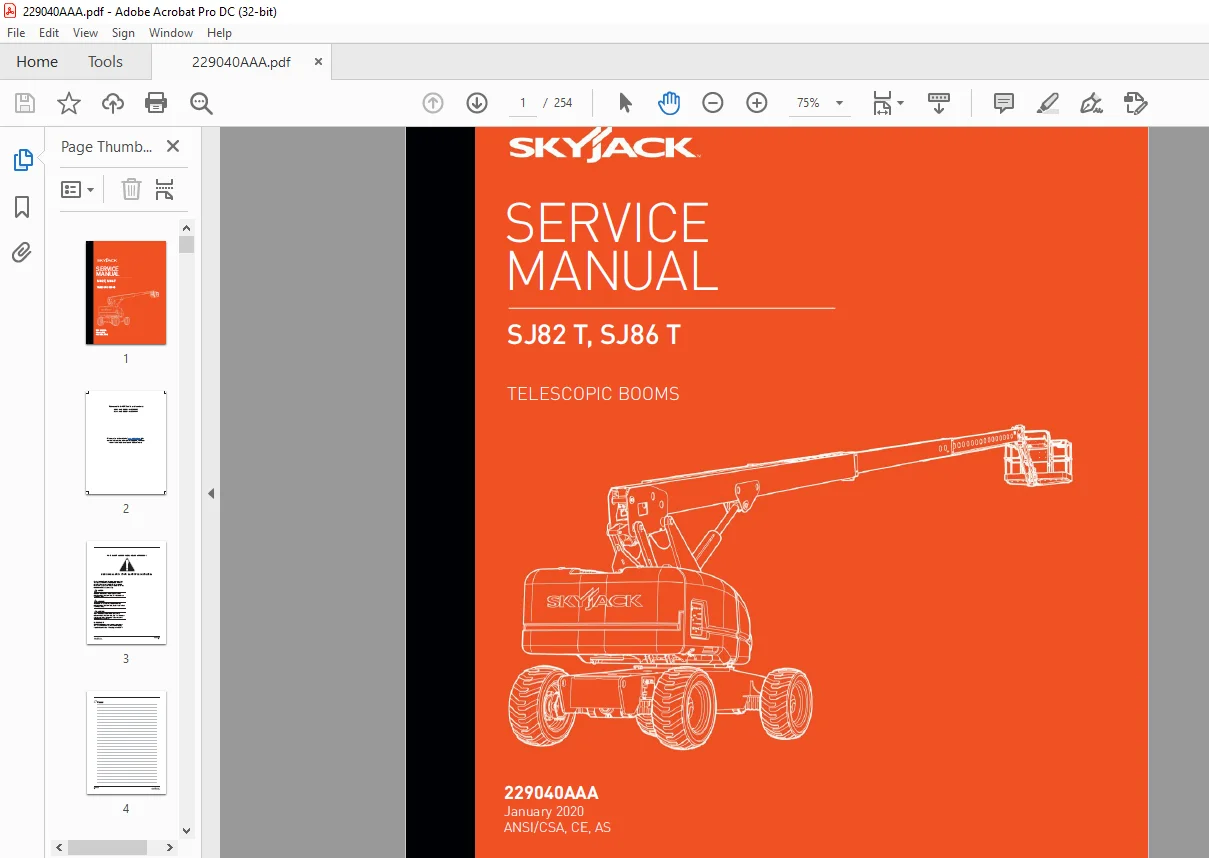
Skyjack SJ82T, SJ86T Telescopic Booms Service Manual 229040AAA – PDF DOWNLOAD
$28.95
Skyjack SJ82T, SJ86T Telescopic Booms Service Manual 229040AAA – PDF DOWNLOAD
Description
Skyjack SJ82T, SJ86T Telescopic Booms Service Manual 229040AAA – PDF DOWNLOAD
FILE DETAILS:
Skyjack SJ82T, SJ86T Telescopic Booms Service Manual 229040AAA – PDF DOWNLOAD
Language : English
Pages :254
Downloadable : Yes
File Type : PDF
DESCRIPTION:
Skyjack SJ82T, SJ86T Telescopic Booms Service Manual 229040AAA – PDF DOWNLOAD
Scheduled Maintenance Operator’s Responsibility for Maintenance;
SKYJACK is continuously improving and expanding product features on its equipment, therefore, specifications
and dimensions are subject to change without notice.
Aerial Platform and Mobile Elevating Work Platform (MEWP) Definition
A mobile device that has a positionable platform supported from ground level by a structure.
Purpose of Equipment
The SKYJACK Veritcal Mast series aerial platform are designed to transport and raise personnel, tools and materials
to overhead work areas.
Use of Equipment
The aerial platform is a highly maneuverable, mobile work station. Lifting and driving must be on a flat, level,
compacted surface.
Manuals:
Operating:
The operating manual is considered a fundamental part of the aerial platform. It is a very important way to
communicate necessary safety information to users and operators. A complete and legible copy of this manual
must be kept in the provided weather-resistant storage compartment on the aerial platform at all times.
Service & Maintenance:
The purpose of this is to provide the customer with the servicing and maintenance procedures essential for
the promotion of proper machine operation for its intended purpose.
All information in this manual should be read and understood before any attempt is made to service the machine.
The updated copy of the manuals are found on the company’s
Operator:
The operator must read and completely understand both this operating manual and the safety panel label located
on the platform and all other warnings in this manual and on the aerial platform. Compare the labels on the aerial
platform with the labels found within this manual. If any labels are damaged or missing, replace them immediately.
IMAGES PREVIEW OF THE MANUAL:
TABLE OF CONTENTS:
Skyjack SJ82T, SJ86T Telescopic Booms Service Manual 229040AAA – PDF DOWNLOAD
Table of Contents 5
Section 1 – Scheduled Maintenance 11
1 1 Read and Heed 11
1 1-1 Aerial Platform and Mobile Elevating Work Platform Definition 11
1 1-2 Purpose of Equipment 11
1 1-3 Use of Equipment 11
1 1-4 Manual 11
1 1-5 Service Policy and Warranty 11
1 1-6 Operator Safety Reminders, Warnings and Precautions 11
1 2 Maintenance and Service 12
1 2-1 Maintenance and Inspection Schedule 12
1 2-2 Owner’s Annual Inspection Record 12
1 2-3 Replacement Parts 12
1 2-4 Maintenance and Service Safety Tips 12
1 2-5 Hydraulic System & Component Maintenance and Repair 13
1 2-6 Hydraulic Maintenance Hints 13
1 2-7 Railing Maintenance and Repair 14
1 3 Scheduled Maintenance 15
1 3-1 Service Bulletins 15
1 3-2 Maintenance and Inspection 15
1 3-3 Maintenance Instructions 15
1 4 Owner’s Annual Inspection Record 16
1 5 Pre-Delivery/Maintenance Inspection Checklist 17
1 6 Scheduled Maintenance Inspections 18
1 6-1 Electrical 18
1 6-2 Hydraulic 18
1 6-3 Labels (B) 18
1 6-4 Limit switches (B) 18
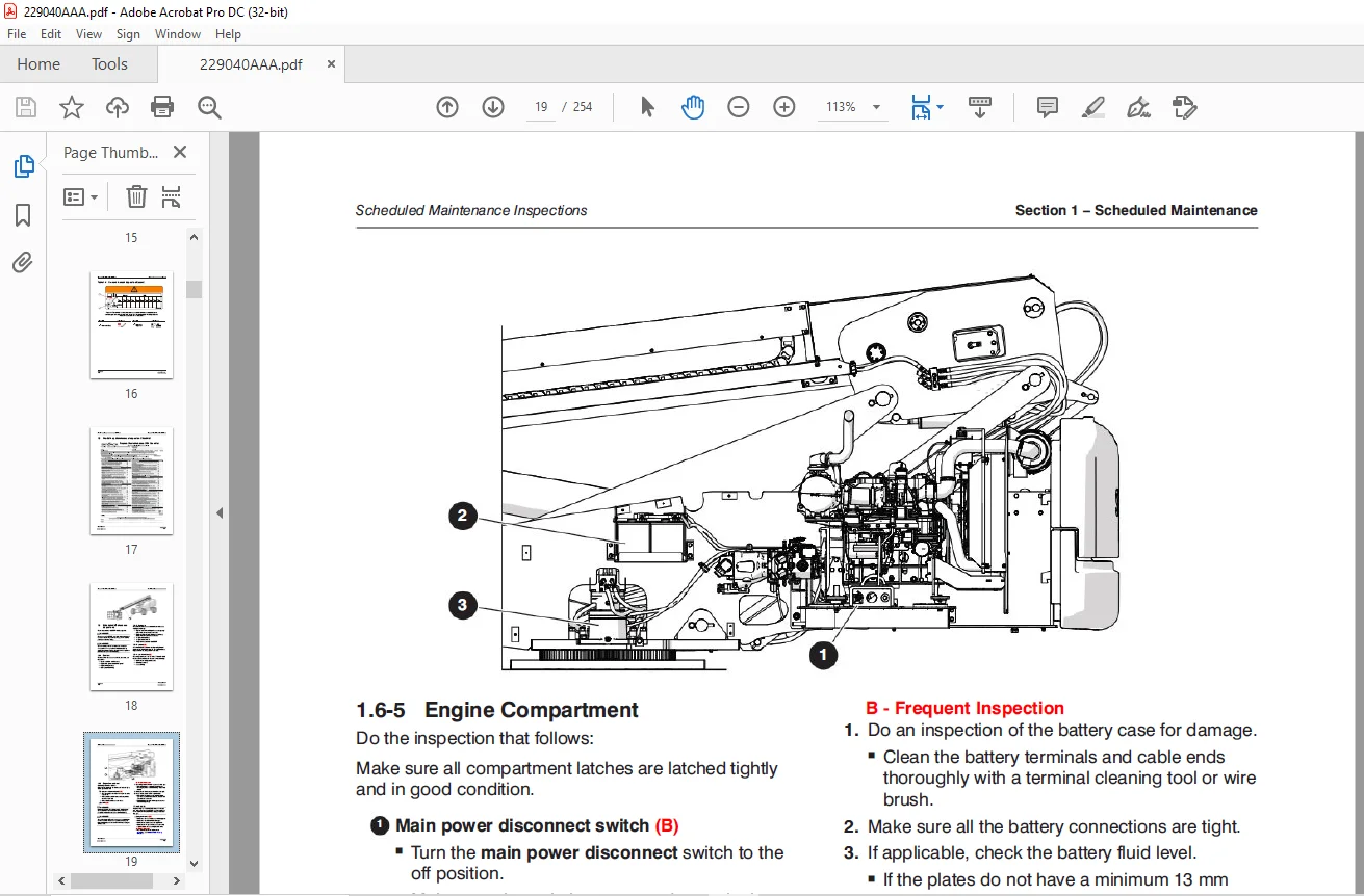
1 6-5 Engine Compartment 19
1 6-6 Control Compartment 22
1 6-7 Base 24
1 6-8 Platform Assembly 26
1 6-9 Boom Assembly 27
1 6-10 Optional equipment (B) 29
1 7 Function Tests 30
Section 2 – Maintenance Tables and Diagrams 31
2 1 Standard Hose Numbering System 31
2 2 MEWP Torque Specifications 33
2 3 Axle Torque Specifications 34
2 4 Torque Specifications for Fasteners (US) 35
2 5 Torque Specifications for Fasteners (Metric) 36
2 6 Torque Specifications for Hydraulic Couplings & Hoses 37
2 7 Axles Maintenance Intervals 38
2 8 Tire Specifications 39
2 9 Floor Loading Pressure 40
2 10 Hydraulic Specifications & Gear Oil 41
2 11 Specifications & Features – Dimensional Data 42
2 12 Specifications & Features – Performance and Speeds 43
2 13 Engine Specifications 44
2 14 Axle Oscillation Diagrams 45
2 15 Dimension and Reach Diagram – SJ82 T 46
2 16 Dimension and Reach Diagram – SJ86 T 47
Section 3 – System Component Identification and Schematics 49
3 1 Electrical Symbol Chart 50
3 2 Hydraulic Symbol Chart 51
3 3 Wire Number and Color Code 52
3 4 Wire Numbers and Color Codes – Additional 53
3 5 Hydraulic Parts List 54
3 6 Electrical Parts List 57
3 7 Hourmeter/Counter Harness – CE 62
3 8 Rotary Manifold Port Identification 63
3 9 System and Drive Pump Port Identification 65
3 10 Drive Motors Port Identification 66
3 11 Jib Valve Port Identification 67
3 12 No Jib Valve Port Identification 68
3 13 Brake Manifold Port Identification 69
3 14 Main Manifold Port Identification 71
3 15 Main Manifold Electrical Component Identification 72
3 16 Main Manifold Hydraulic Component Identification 73
3 17 Main Harness Wiring Diagram 74
3 18 Boom Lift Valve Harness 75
3 19 Differential Lock Harness 76
3 20 Platform Rotate & Jib Harnesses 77
3 21 Platform to Base Control Cable Harnesses 78
3 22 Limit Switch Connections 79
3 23 Load Sensing Cable Connection – CE & AS 80
3 24 ECU Engine Wiring Diagram – Deutz Diesel Engine 81
3 25 Glow Plug and EGR Harnesses – Deutz Diesel Engine 82
3 26 Generator and Oil Cooler Harness Connections 83
3 27 Generator Wiring 84
3 28 Platform Work Light 85
3 29 Positive Air Shut-Off Option Harness 86
3 30 Dual Capacity Sensing Module 87
3 31 Load Circuit – ANSI/CSA with Deutz TD2 9L and Arctic Package 88
3 32 Hydraulic Schematic 89
3 33 Platform Controls Wiring – SJ82 T 90
3 34 Platform Controls Wiring – SJ86 T with Deutz TD2 9L or D2011 Engines 91
3 35 Platform Controls Wiring – SJ86 T with Deutz TCD2 2 Engine 92
3 36 Base Controls Wiring – SJ82 T ANSI/CSA – Deutz TD2 9L 93
3 37 Base Controls Wiring – SJ82 T ANSI/CSA – Deutz TD2 9L with Positive Air Shut-Off 94
3 38 Base Controls Wiring – SJ82 T ANSI/CSA – Deutz D2011 95
3 39 Base Controls Wiring – SJ86 T ANSI/CSA – Deutz TD2 9L 96
3 40 Base Controls Wiring – SJ86 T ANSI/CSA – Deutz TD2 9L with Positive Air Shut-Off 97
3 41 Base Controls Wiring – SJ86 T ANSI/CSA & AS – Deutz D2011 98
3 42 Base Controls Wiring – SJ86 T CE – Deutz TCD2 2 99
3 43 Base Controls Wiring – SJ86 T CE – Deutz D2011 100
3 44 Base Controls Wiring – SJ86 T CE – Deutz TD2 9L 101
3 45 Electrical Schematic – ANSI/CSA Deutz TD2 9L 102
3 46 Electrical Schematic – ANSI/CSA & AS Deutz D2011 103
3 47 Electrical Schematic – CE Deutz TCD2 2 104
3 48 Electrical Schematic – CE Deutz D2011 105
3 49 Engine Electrical Schematic – Deutz TD2 9L 106
3 50 Engine Interface Harness Schematic – Deutz TD2 9L 107
3 51 Engine Electrical Schematic – Deutz TCD2 2 108
3 52 Engine Interface Harness Schematic – Deutz TCD2 2 109
Section 4 – Troubleshooting Information 111
4 1 Introduction 111
4 2 Electrical System 112
4 2-1 All Controls Inoperative 112
4 2-2 No Power 113
4 2-3 Engine Will Not Crank 114
4 2-4 Engine Cranks but Will Not Start 117
4 2-5 Glow Plug Circuit Inoperative – Deutz D2011 diesel engine 118
4 2-6 Glow Plug Circuit Inoperative – Deutz D2 9 diesel engine 118
4 2-7 All Base Control Console Inoperative 119
4 2-8 No Movement from Base Control Console 120
4 2-9 All Controls Inoperative From Platform Control Console 127
4 2-10 Throttle Inoperative, Mid and High – Deutz D2 9L 136
4 2-11 Mid Throttle Inoperative 137
4 2-12 High Throttle Inoperative 138
4 2-13 Brake will not Release 139
4 2-14 No Drive and Steer 139
4 2-15 No High Speed Drive 142
4 2-16 No Elevated Drive 143
4 2-17 Direction Sensing Inoperative 144
4 2-18 Steer Direction Sensing Inoperative 144
4 2-19 No boom down or extend Functions from Base or Platform Consoles (ANSI) 145
4 2-20 No boom down Function from Base or Platform Consoles (ANSI) 145
4 2-21 No boom extend Function from Base or Platform Consoles (ANSI) 146
4 2-22 No boom down Function from Base or Platform Consoles (CE, AS) 146
4 2-23 No boom extend Function from Base or Platform Consoles (CE, AS) 147
4 3 Hydraulic System 148
4 3-1 All Controls Inoperative 148
4 3-2 All Boom Functions Inoperative 148
4 3-3 No Main Boom Up 148
4 3-4 No Main Boom Down 148
4 3-5 No Turret Rotate 149
4 3-6 No Boom Extend 150
4 3-7 No Boom Retract 150
4 3-8 No Jib Up 151
4 3-9 No Jib Down 152
4 3-10 No Platform Rotation 152
4 3-11 Platform will not Level 153
4 3-12 Brake will not Release 154
4 3-13 Brake will not Engage 154
4 3-14 No Drive 155
4 3-15 Differential Lock will not Engage 155
4 3-16 No High Speed Drive 155
4 3-17 No Steer 156
4 4 Load Sensing System – CE 158
4 4-1 Green LED on Load Sense/Dual Load Zone Module is not on 158
4 4-2 Load Sense indicates overload or overload warning with platform empty or below weight 158
4 4-3 Load Sense/Dual Load Zone Module Error 159
4 4-4 No Light/Alarm when Platform is Overloaded 160
Section 5 – Procedures 161
5 1 General 161
5 1-1 Safety and Workmanship 161
5 2 Platform 162
5 2-1 Human Machine Interface (HMI) 162
5 2-2 User Interface Keys 162
5 2-3 SCM Character Functions Charts 163
5 2-4 SCM Operating Values Chart 164
5 2-5 How to Select SCM Functionality 165
5 2-6 How to View SCM Operation 166
5 2-7 How to Unlock and Modify SCM Settings 167
5 2-8 SCM Pin Voltage Reference 168
5 2-9 Fly Boom Switch Voltage References 171
5 2-10 Platform Controller Voltage References 172
5 3 Load Sensing System 173
5 3-1 Load Sensing System Overload Status 173
5 3-2 Dual Capacity Overload Module Function Table 174
5 3-3 Calibration of Load Sensing System 175
5 4 Boom 177
5 4-1 Check Wear Pads 177
5 4-2 Shim Wear Pads 177
5 4-3 Cable Carrier Repair 177
5 4-4 Rotary Actuator Bolt Torque Procedure 177
5 4-5 Boom Section Wear Pad Replacement 178
5 4-6 Platform and Jib Boom Removal 179
5 4-7 Platform Removal (no Jib Boom) 181
5 4-8 Operating Machine Functions from Base Controls 183
5 4-9 Fly Boom Section Removal 184
5 4-10 Mid Boom Section Removal 185
5 4-11 Mid Boom Section Installation 186
5 4-12 Fly Boom Section Installation 187
5 4-13 Platform and Jib Boom Installation 187
5 4-14 Platform Installation (no Jib Boom) 188
5 4-15 Platform Control Console Connection 189
5 4-16 Extension Cylinder and Wire Rope Replacement 190
5 4-17 Extension Cylinder and Cable Assembly Removal 190
5 4-18 Extension Cylinder and Wire Rope Assembly Installation 193
5 4-19 Proper Wire Rope Tension 195
5 4-20 Wire Rope Inspection 196
5 4-21 Limit Switch Checking and Adjusting 197
5 4-22 Directional Sensing Limit Switch (LS1) 198
5 4-23 High Speed Drive / Tilt Override Limit Switch (LS2) 199
5 4-24 Fly-in Limit Switch (LS3) 201
5 4-25 Boom Angle (Dual Load) Limit Switch (LS4) 202
5 4-26 Boom Extension (Dual Load) Limit Switch (LS5) 204
5 4-27 Lift Cushion Limit Switch (LS6) 206
5 5 Turret 208
5 5-1 Check and Replace the High Pressure Filter 208
5 5-2 Adjust the Turret Rotation Gear Backlash 208
5 5-3 Check the Swing Drive Oil 209
5 5-4 Change the Swing Drive Oil 209
5 5-5 Battery Replacement 210
5 5-6 Turret Rotation Gear Bolt Torque Sequence 210
5 5-7 Electronic Tilt Switch Setup Procedure 211
5 5-8 Check Rotation Bearing for Axial Wear 213
5 5-9 Resetting the Emergency Lowering Counter (CE only) 214
5 6 Deutz Diesel Engines 215
5 6-1 Replace Engine Oil and Filter 215
5 6-2 Replace the Fuel Filter 216
5 6-3 Replace the Air Filter 216
5 6-4 Check the Engine Belt 216
5 6-5 Check the Oil Cooler (Deutz D2011 only) 216
5 6-6 Deutz TD2 9L Fault Codes 217
5 7 Hydraulic Tank 237
5 7-1 Change the Hydraulic Tank Filter 237
5 7-2 Change the Hydraulic Oil 237
5 8 Manifolds and Hydraulic Pumps 238
5 8-1 Hydraulic Brake Pressure Adjustment 238
5 8-2 Hydraulic Standby Pressure Adjustment 239
5 8-3 Hydraulic High Pressure Adjustment 240
5 8-4 Hydraulic System Relief Valve Adjustment 241
5 8-5 Turret Rotate Relief Valve Adjustment 242
5 8-6 Platform Level Relief Valve Adjustment 242
5 8-7 Fly Boom Relief Valve Adjustment 243
5 8-8 Test Charge Pump Pressure on Drive Pump 243
5 8-9 Test Forward Drive Pressure on Drive Pump 244
5 8-10 Test Reverse Drive Pressure on Drive Pump 244
5 9 Axles 245
5 9-1 Change the Oil in the Axles 245
5 9-2 Check the Oil Level in the Torque Hubs 245
5 9-3 Change the Oil in the Torque Hubs 245
5 9-4 Check the Oil Level in the Axle Gearbox 246
5 9-5 Change the Oil in the Axle Gearbox 246
5 9-6 Brake Inspection 247
5 9-7 Oscillating Cylinder Bolt Replacement 247
5 9-8 Oscillating Cylinder Replacement 248
5 9-9 Bleed the Oscillating Axle Cylinders 249
5 9-10 Test the Oscillating Axle Cylinders 250
5 10 Grease Points 251
5 10-1 Grease the Turret Ring Gear 251
5 10-2 Grease the Turret Swing Drive 251
5 10-3 Grease the Axles 252
5 10-4 Grease the Drive Shaft 252
Questions? Email us: [email protected]
PLEASE NOTE:
- This is the SAME exact manual used by your dealers to fix your vehicle.
- The same can be yours in the next 2-3 mins as you will be directed to the download page immediately after paying for the manual.
- Any queries / doubts regarding your purchase, please feel free to contact [email protected]
S.M