Trusted Business
Verified & Licensed
Virus Free Files
100% Safe Downloads
Secure Payment
SSL Protected
Instant Delivery
Available Immediately

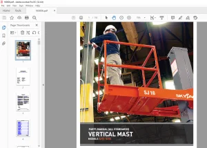
Skyjack SJ8831 RT SJ8841 RT Rough Terrain Scissors Service Manual 157945AE – PDF DOWNLOAD
$28.95
Skyjack SJ8831 RT SJ8841 RT Rough Terrain Scissors Service Manual 157945AE – PDF DOWNLOAD
SJRT 8831 36,000,233 to 36,000,275
SJRT 8841 40,000,728 to 40,001,134
Instant PDF Download
Available immediately
Save to Your Device
Download & keep forever
Antivirus Scanned
100% virus-free
Trusted Worldwide
175,000+ customers
Description
Skyjack SJ8831 RT SJ8841 RT Rough Terrain Scissors Service Manual 157945AE – PDF DOWNLOAD
FILE DETAILS:
Skyjack SJ8831 RT SJ8841 RT Rough Terrain Scissors Service Manual 157945AE – PDF DOWNLOAD
Language : English
Pages : 164
Downloadable : Yes
File Type : PDF
DESCRIPTION:
Skyjack SJ8831 RT SJ8841 RT Rough Terrain Scissors Service Manual 157945AE – PDF DOWNLOAD
SJRT 8831 36,000,233 to 36,000,275
SJRT 8841 40,000,728 to 40,001,134
SKYJACK is continuously improving and expanding product features on its equipment, therefore,
specifications and dimensions are subject to change without notice.
specifications and dimensions are subject to change without notice.
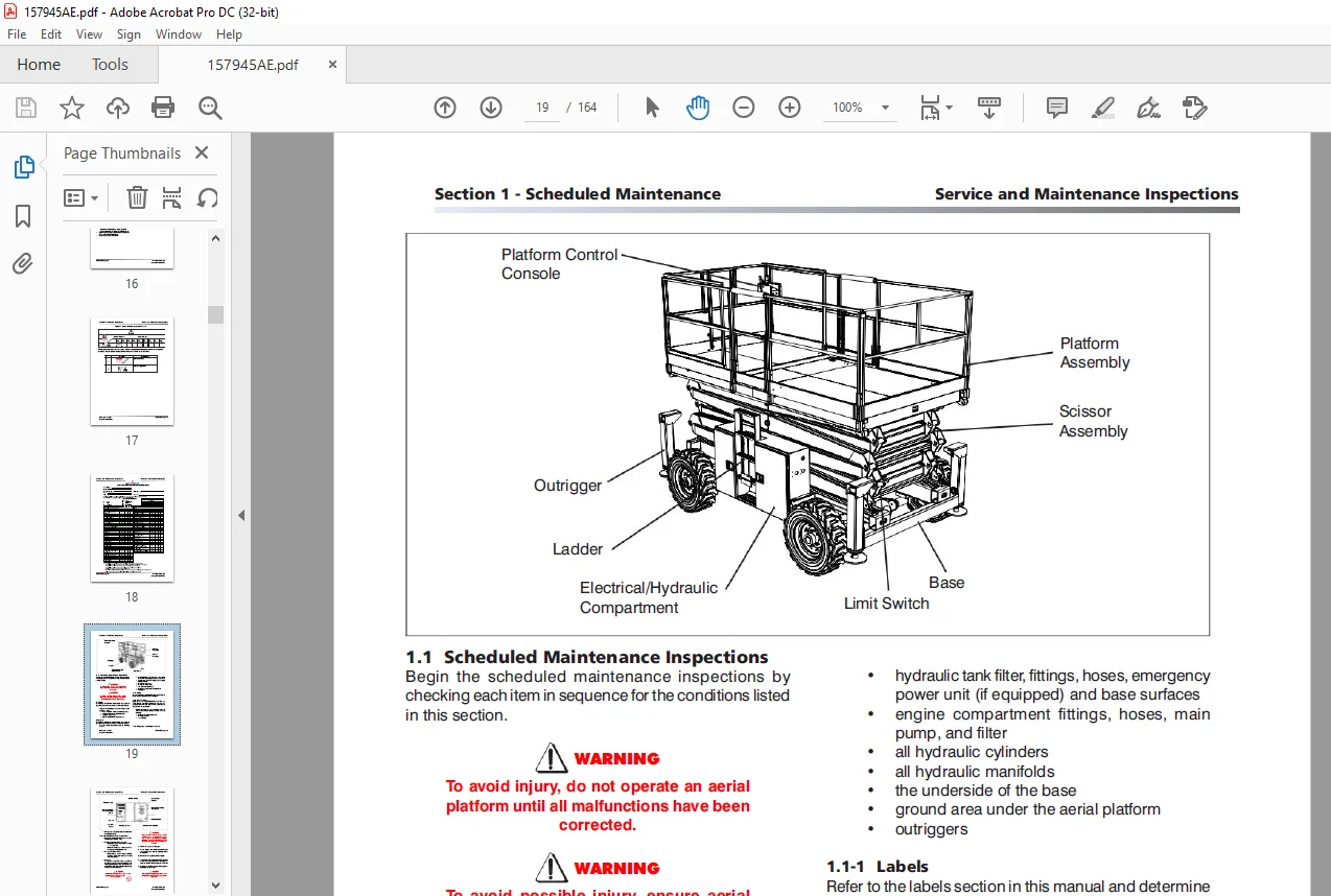
Aerial Platform Definition:
A mobile device that has an adjustable position platform supported from ground level by a
structure.
A mobile device that has an adjustable position platform supported from ground level by a
structure.
Purpose of Equipment:
The SKYJACK Rough Terrain’s mid and full size aerial platforms are designed to transport and raise
personnel, tools and materials to overhead work areas.
The SKYJACK Rough Terrain’s mid and full size aerial platforms are designed to transport and raise
personnel, tools and materials to overhead work areas.
Use of Equipment:
The aerial platform is a highly maneuverable, mobile work station. Lifting and driving must be on a
flat, level, compacted surface. It can be driven over uneven terrain only when the platform is
fully lowered.
The aerial platform is a highly maneuverable, mobile work station. Lifting and driving must be on a
flat, level, compacted surface. It can be driven over uneven terrain only when the platform is
fully lowered.
Manuals:
Operating:
The operating manual is considered a fundamental part of the aerial platform. It is a very
important way to communicate necessary safety information to users and operators. A complete and
legible copy of this manual must be kept in the provided weather-resistant storage compartment on
the aerial platform at all times.
Service & Maintenance
- The purpose of this is to provide the customer with the servicing and maintenance procedures
essential for the promotion of proper machine operation for its intended purpose. - All information in this manual should be read and understood before any attempt is made to service
the machine.
Operator:
The operator must read and completely understand both this operating manual and the safety panel
label located on the platform and all other warnings in this manual and on the aerial platform.
Compare the labels on the aerial platform with the labels found within this manual. If any labels
are damaged or missing, replace them immediately.
TABLE OF CONTENTS:
Skyjack SJ8831 RT SJ8841 RT Rough Terrain Scissors Service Manual 157945AE – PDF DOWNLOAD
Table of Contents....................................................................................................................................  3
Section 1 - Schedule Maintenance.....................................................................................................................  5
	Operator’s Responsibility for Maintenance........................................................................................................  6
		Aerial Platform Definition...................................................................................................................  6
		Purpose of Equipment.........................................................................................................................  6
		Use of Equipment.............................................................................................................................  6
		Manuals......................................................................................................................................  6
		Operating....................................................................................................................................  6
		Service & Maintenance........................................................................................................................  6
		Operator Safety Reminders....................................................................................................................  7
		Electrocution Hazard.........................................................................................................................  8
		Safety Precautions...........................................................................................................................  9
		Maintenance and Inspection Schedule.......................................................................................................... 13
		Owner’s Annual Inspection Record............................................................................................................. 13
		Replacement Parts............................................................................................................................ 13
		Maintenance and Service Safety Tips.......................................................................................................... 13
		Hydraulic System & Component Maintenance and Repair.......................................................................................... 14
		Mainenance Hints............................................................................................................................. 15
		Railing Maintenance and Repair............................................................................................................... 15
	Service and Maintenance.......................................................................................................................... 15
		About this Section........................................................................................................................... 16
		Service Bulletins............................................................................................................................ 16
		Maintenance and Inspection................................................................................................................... 16
		Maintenance Instructions..................................................................................................................... 16
	Tables........................................................................................................................................... 17
		Table 1.1  Owner’s Annual Inspection Record.................................................................................................. 17
		Table 1.2  Maintenance and Inspection Checklist.............................................................................................. 18
	Scheduled Maintenance............................................................................................................................ 19
		1.1 Scheduled Maintenance Inspections........................................................................................................ 19
		1.2 Function Tests........................................................................................................................... 31
Section 2 - Maintenance Tables and Diagrams.......................................................................................................... 41
	Tables........................................................................................................................................... 42
		Table 2.1  Specifications and Features....................................................................................................... 42
		Table 2.2a  Maximum Platform Capacities (Evenly Distributed)................................................................................. 43
		Table 2.2b  Maximum Platform Capacities (Evenly Distributed w/ Optional #7 Tires)............................................................ 44
		Table 2.3  Tire Specifications............................................................................................................... 45
		Table 2.4  Floor Loading Pressure............................................................................................................ 47
		Table 2.5  Rough Terrain Scissor Fluids...................................................................................................... 48
		Table 2.6  Torque Specifications............................................................................................................. 50
Section 3 - System component identification and schematics........................................................................................... 51
	Charts........................................................................................................................................... 52
		3.1  Hydraulic Symbol Chart.................................................................................................................. 52
		3.2  Electrical Symbol Chart................................................................................................................. 53
	Parts List....................................................................................................................................... 54
		3.3  Hydraulic Parts List.................................................................................................................... 54
		3.4  Electrical Parts List................................................................................................................... 57
	Diagrams and Schematics.......................................................................................................................... 63
		3.5  Platform Control Console Diagram with All Options (ANSI/CSA)............................................................................ 63
		3.6  Control Cable Assemblies Diagram........................................................................................................ 64
		3.7  Outrigger/Hydraulic Generator Control Console Wiring.................................................................................... 65
		3.8  Main Manifold Components & Port Identifications......................................................................................... 67
		3.9  Hydraulic Manifold Components & Port Identifications.................................................................................... 68
		3.10a  Hydraulic Schematic................................................................................................................... 69
		3.10b  Hydraulic Schematic................................................................................................................... 70
		3.11  Main Manifold Wiring Diagram (ANSI/CSA)................................................................................................ 71
		3.12  Horn, Light, Beeper Wiring Diagram (ANSI/CSA).......................................................................................... 72
		3.13  Powered Extension Platform - Electrical Connection Diagram............................................................................. 73
		3.14  Electrical Panel Diagram - 12kW Generator Modification (ANSI/CSA)...................................................................... 74
		3.15  12kW Generator Hydraulic and Electric Wiring Schematics (ANSI/CSA)..................................................................... 75
		3.16  Electrical Inverter Wiring Diagram..................................................................................................... 76
		3.17  Engine Harness Wiring Diagram - Kubota Diesel Engine................................................................................... 77
		3.18  Engine Harness Wiring Diagram - GM Dual Fuel Engine.................................................................................... 78
		3.19  Engine Harness Wiring Diagram - Kubota Dual Fuel Engine................................................................................ 79
		3.20  Electrical Panel Diagram (ANSI/CSA).................................................................................................... 80
		3.21  Electrical Schematic - Kubota Diesel Engine All Options (ANSI/CSA)..................................................................... 81
		3.22  Electrical Schematic - GM Dual Fuel Engine No Options (ANSI/CSA)....................................................................... 82
		3.23  Electrical Schematic - GM Dual Fuel Engine All Options (ANSI/CSA)...................................................................... 83
		3.24  Electrical Schematic - Kubota Dual Fuel Engine No Options (ANSI/CSA)................................................................... 84
		3.25  Electrical Schematic - Kubota Dual Fuel Engine All Options (ANSI/CSA).................................................................. 85
		3.26  Interface & Engine Electrical Schematic - GM Dual Fuel Engine  ........................................................................ 86
		3.27  Electrical Panel Diagram - Outrigger Option............................................................................................ 87
		3.28  Outrigger Wiring Diagram............................................................................................................... 88
		3.29  Electrical Panel Diagram - Oil Cooler Option........................................................................................... 89
		3.30  Hydraulic Generator Electrical Panel Diagram - Kubota Engine (ANSI/CSA)................................................................ 90
		Introduction................................................................................................................................. 93
Section 4 - Troubleshooting Information ............................................................................................................. 91
	Electrical System................................................................................................................................ 94
		4.1-1 All Controls Inoperative............................................................................................................... 94
		4.1-2 No Power to Platform (ANSI/CSA)........................................................................................................ 94
		4.1-3 All Functions Inoperative from Platform ............................................................................................... 94
		4.1-4 Engine will Not Crank from Platform.................................................................................................... 95
		4.1-5 Engine will Not Crank from Platform Controls (Additional for GM Dual Fuel)............................................................. 95
		4.1-6 Engine will Not Crank from Base Controls (GM dual fuel)................................................................................ 96
		4.1-7 Engine will Not Crank from Base Controls (Kubota diesel)............................................................................... 96
		4.1-8 Engine Cranks but Stops Cranking after a few seconds................................................................................... 96
		4.1-9 Glow Plugs Inoperative from Engine Controls ........................................................................................... 97
		4.1-10 Glow Plugs Inoperative from Platform (Additional)..................................................................................... 97
		4.1-11 Engine Cranks but will Not Start (Kubota diesel)...................................................................................... 97
		4.1-12 Engine Cranks but will Not Start (GM dual fuel)....................................................................................... 98
		4.1-13 Mid Throttle Inoperative (on demand) (GM Dual Fuel)................................................................................... 99
		4.1-14 High Throttle Inoperative ............................................................................................................100
		4.1-15 High Throttle Inoperative (additional for GM dual fuel)...............................................................................100
		4.1-16 Drive and Steer Inoperative (Machines without outriggers option)......................................................................101
		4.1-17 Drive and Steer Inoperative (machines with outriggers option).........................................................................101
		4.1-18 Brakes will Not Release...............................................................................................................102
		4.1-19 Steer Right Inoperative...............................................................................................................102
		4.1-20 Steer Left Inoperative................................................................................................................103
		4.1-21 Reverse Drive Inoperative.............................................................................................................103
		4.1-22 Forward Drive Inoperative.............................................................................................................104
		4.1-23 First Drive Speed and Steering Inoperative............................................................................................105
		4.1-24 Second Drive Speed Inoperative........................................................................................................105
		4.1-25 Third Drive Speed Inoperative.........................................................................................................106
		4.1-26 High/Low Range Speed Inoperative......................................................................................................106
		4.1-27 Up Circuit Inoperative from Platform or Base (machines without outriggers)............................................................107
		4.1-28 Up Circuit Inoperative from Base......................................................................................................108
		4.1-29 Platform will Not Lift from Platform or Base Controls with Outriggers Retracted (lift operates correctly with outriggers extended)....108
		4.1-30 Platform will Not Lift from Platform or Base Controls with Outriggers Extended........................................................109
		4.1-31 Down Circuit Inoperative from Platform or Base........................................................................................110
		4.1-32 Down Circuit Inoperative from Base....................................................................................................111
		4.1-33 Powered Extension Platform Inoperative................................................................................................111
		4.1-34 Powered Extension Platform will Not Extend............................................................................................111
		4.1-35 Powered Extension Platform will Not Retract...........................................................................................112
		4.1-36 Hydraulic Generator Inoperative.......................................................................................................112
		4.1-37 Hydraulic Generator will Not Shut Off from Generator Switch...........................................................................113
		4.1-38 All Outriggers Inoperative (Auto-level and manual)....................................................................................113
		4.1-39 All Outriggers Inoperative (Auto-level and manual from platform controls).............................................................114
		4.1-40 All Outriggers Inoperative  (Base controls)...........................................................................................114
		4.1-41 All Outriggers Inoperative (Auto-level) A: Led Power Indicator Light at Outrigger Control Module (OCM1) Not on Constant...............114
		4.1-42 All Outriggers Inoperative (Auto Level Only) B: Led Power Indicator Light at Outrigger Control Module (OCM1) Flashing.................115
		4.1-43 Left Front Outrigger Inoperative Manually.............................................................................................116
		4.1-44 Right Front Outrigger Inoperative Manually............................................................................................116
		4.1-45 Right Rear Outriggers Inoperative Manually............................................................................................116
		4.1-46 Left Rear Outriggers Inoperative Manually.............................................................................................117
		4.1-47 Individual Outrigger Functions Inoperative (auto-level) ..............................................................................117
		4.1-48 Auto-level Inoperative................................................................................................................117
		4.1-49 Auto All Up Inoperative (Retract).....................................................................................................118
	Hydraulic System.................................................................................................................................119
		4.2-1 All Functions Inoperative..............................................................................................................119
		4.2-2 Steering Inoperative...................................................................................................................119
		4.2-3 Steer and First Drive Speed Inoperative................................................................................................119
		4.2-4 Lift and Second Drive Speed Inoperative................................................................................................119
		4.2-5 Drive Inoperative......................................................................................................................119
		4.2-6 Reverse Drive Inoperative..............................................................................................................120
		4.2-7 Forward Drive Inoperative..............................................................................................................120
		4.2-8 Brakes will Not Release................................................................................................................120
		4.2-9 Brakes will Not Release (Internal Brake)...............................................................................................120
		4.2-10 Brake Slips (Internal Brake)..........................................................................................................120
		4.2-11 Brake Drags or Runs Hot (Internal Brake)..............................................................................................121
		4.2-12 Up Circuit Inoperative................................................................................................................121
		4.2-13 Down Circuit Inoperative..............................................................................................................122
		4.2-14 Powered Extension Platform Inoperative................................................................................................122
		4.2-15 Hydraulic Generator Inoperative.......................................................................................................122
		4.2-16 All Outriggers Inoperative............................................................................................................122
		4.2-17 Left Front Outrigger Inoperative......................................................................................................122
		4.2-18 Right Front Outrigger Inoperative.....................................................................................................122
		4.2-19 Right Rear Outrigger Inoperative......................................................................................................123
		4.2-20 Left Rear Outrigger Inoperative.......................................................................................................123
		4.2-21 Outriggers Drift In...................................................................................................................123
		Safety and Workmanship.......................................................................................................................126
Section 5 - Procedures...............................................................................................................................125
	Base.............................................................................................................................................126
		5.1-1 Hydraulic System and Brake Adjustment Procedure (If Equipped) .........................................................................126
		5.1-2 Brake Assembly and Disassembly (If Equipped)...........................................................................................127
		5.1-3 Holding Torque Testing Procedure.......................................................................................................129
		5.1-4 Winching and Towing Procedures and Brake System........................................................................................129
		5.1-5 System Lift and Pressure Adjustment....................................................................................................130
		5.1-7 Wheel Bolt/Nut Inspection and Torquing Procedure.......................................................................................131
		5.1-8 Wheel Reinstallation and Torquing Procedure............................................................................................132
		5.1-9 Front Axle Hub Procedure...............................................................................................................133
	Engines..........................................................................................................................................139
		5.2-1 ECU Pin Reference Chart (GM)...........................................................................................................139
		5.2-2 Throttle Actuator (GM).................................................................................................................140
		5.2-3 GM Map and IAT Sensor (GM).............................................................................................................141
		5.2-4 Engine Coolant Temperature Sensor (GM).................................................................................................142
		5.2-5 LPG Temperature Sensor (GM)............................................................................................................143
		5.2-6 Fuse Block Layout (GM).................................................................................................................144
		5.2-7 Kubota Dual Fuel (DF972) Resistance Checks.............................................................................................145
	Outriggers.......................................................................................................................................146
		5.3-1 Auto-Leveling Outrigger PC Board Layout................................................................................................146
		5.3-2 Outrigger Mechanical Limit Switch Wiring Diagram.......................................................................................147
		5.3-3 Auto-Leveling Outrigger Setting and Error Codes........................................................................................148
		5.3-4 Auto-Leveling Outrigger Error Code Breakdown...........................................................................................149
		5.3-5 Hand Held Calibration/Diagnostic Tool Key Functions....................................................................................150
		5.3-6 Outrigger Control Module Instructions..................................................................................................151
		5.3-7 Auto-Leveling Outrigger Control Module Pin Reference Chart.............................................................................154
		5.3-8 Outrigger Upper Limit Switch (LS61, LS62, LS63, LS64) Replacement and Adjustment.......................................................155
		5.3-9 Outrigger Lower Limit Switch (LS65, LS66, LS67, LS68) Replacement and Adjustment.......................................................156
	Scissors.........................................................................................................................................158
		5.4-1 End of Stroke Limit Switch (LS4) Replacement and Adjustment............................................................................158
		5.4-2 High Speed Cutout Limit Switch (LS5) Replacement and Adjustment........................................................................160
	Platform.........................................................................................................................................162
		5.5-1 Gate Springe Hinge Adjustment..........................................................................................................162
IMAGES PREVIEW OF THE MANUAL:
Customer Support: [email protected]
PLEASE NOTE:
- This is the SAME MANUAL used by the dealerships to diagnose your vehicle
- No waiting for couriers / posts as this is a PDF manual and you can download it within 2 minutes time once you make the payment.
- Your payment is all safe and the delivery of the manual is INSTANT – You will be taken to the DOWNLOAD PAGE.
- So have no hesitations whatsoever and write to us about any queries you may have : heydownloadss @gmail.com
S.V